fuse diagram MITSUBISHI LANCER EVOLUTION VIII 2004 Workshop Manual
[x] Cancel search | Manufacturer: MITSUBISHI, Model Year: 2004, Model line: LANCER EVOLUTION VIII, Model: MITSUBISHI LANCER EVOLUTION VIII 2004Pages: 166, PDF Size: 3.56 MB
Page 96 of 166
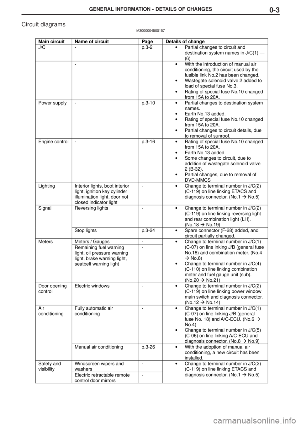
GENERAL INFORMATION - DETAILS OF CHANGES0-3
Main circuit Name of circuit Page Details of change
J/C - p.3-2• Partial changes to circuit and
destination system names in J/C(1) —
(6)
-• With the introduction of manual air
conditioning, the circuit used by the
fusible link No.2 has been changed.
• Wastegate solenoid valve 2 added to
load of special fuse No.3.
• Rating of special fuse No.10 changed
from 15A to 20A.
Power supply - p.3-10• Partial changes to destination system
names.
• Earth No.13 added.
• Rating of special fuse No.10 changed
from 15A to 20A.
• Partial changes to circuit details, due
to removal of sunroof.
Engine control - p.3-16• Rating of special fuse No.10 changed
from 15A to 20A.
• Earth No.13 added.
• Some changes to circuit, due to
addition of wastegate solenoid valve
2 (B-32).
• Partial changes, due to removal of
DVD-MMCS
Lighting Interior lights, boot interior
light, ignition key cylinder
illumination light, door not
closed indicator light-• Change to terminal number in J/C(2)
(C-119) on line linking ETACS and
diagnosis connector. (No.1 " No.5)
Reversing lights -• Change to terminal number in J/C(2)
(C-119) on line linking reversing light
and rear combination light (LH).
(No.18 " No.19)Signal
Stop lights p.3-24• Spare connector (F-28) added, and
circuit partially changed.
Meters / Gauges -Meters
Remaining fuel warning
light, oil pressure warning
light, brake warning light,
seatbelt warning light-• Change to terminal number in J/C(1)
(C-07) on line inking J/B (general fuse
No.18) and combination meter. (No.4
" No.8)
• Change to terminal number in J/C(4)
(C-110) on line linking combination
meter and fuel gauge unit (sub).
(No.20 " No.21)
Door opening
controlElectric windows -• Change to terminal number in J/C(2)
(C-119) on line linking power window
main switch and diagnosis connector.
(No.12 " No.14)
Fully automatic air
conditioning-• Change to terminal number in J/C(1)
(C-07) on line linking J/B (general
fuse No. 18) and A/C-ECU. (No.6 "
No.4)
• Change to terminal number in J/C(5)
(C-06) on line linking A/C-ECU and
diagnosis connector. (No.8 " No.9)Air
conditioning
Manual air conditioning p.3-26• With the adoption of manual air
conditioning, a new circuit has been
installed.
Windscreen wipers and
washers-Safety and
visibility
Electric retractable remote
control door mirrors-• Change to terminal number in J/C(2)
(C-119) on line linking ETACS and
diagnosis connector. (No.1 " No.5)
Circuit diagrams
M3000004500157
Page 109 of 166
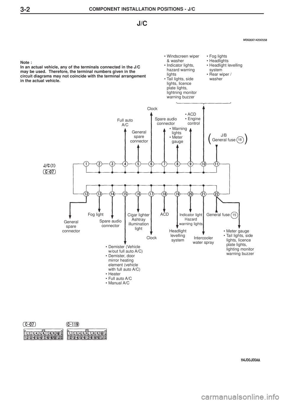
COMPONENT INSTALLATION POSITIONS - J/C3-2
J/C
Note :
In an actual vehicle, any of the terminals connected in the J/C
may be used. Therefore, the terminal numbers given in the
circuit diagrams may not coincide with the terminal arrangement
in the actual vehicle.
• Windscreen wiper
& washer
• Indicator lights,
hazard warning
lights
• Tail lights, side
lights, licence
plate lights,
lightning monitor
warning buzzer• Fog lights
• Headlights
• Headlight levelling
system
• Rear wiper /
washer
Full auto
A/C
General
spare
connector
Clock
Spare audio
connector
• Warning
lights
• Meter
gauge
• ACD
• Engine
control
J/B
General fuse
()18
General
spare
connector
Fog light
Spare audio
connector
• Demister (Vehicle
w/out full auto A/C)
• Demister, door
mirror heating
element (vehicle
with full auto A/C)
• Heater
• Full auto A/C
• Manual A/C
Cigar lighter
Ashtray
illumination
light
Clock
ACD
Headlight
levelling
system
Indicator light
Hazard
warning lights
Intercooler
water spray
General fuse15
• Meter gauge
• Tail lights, side
lights, licence
plate lights,
lighting monitor
warning buzzer
Page 112 of 166
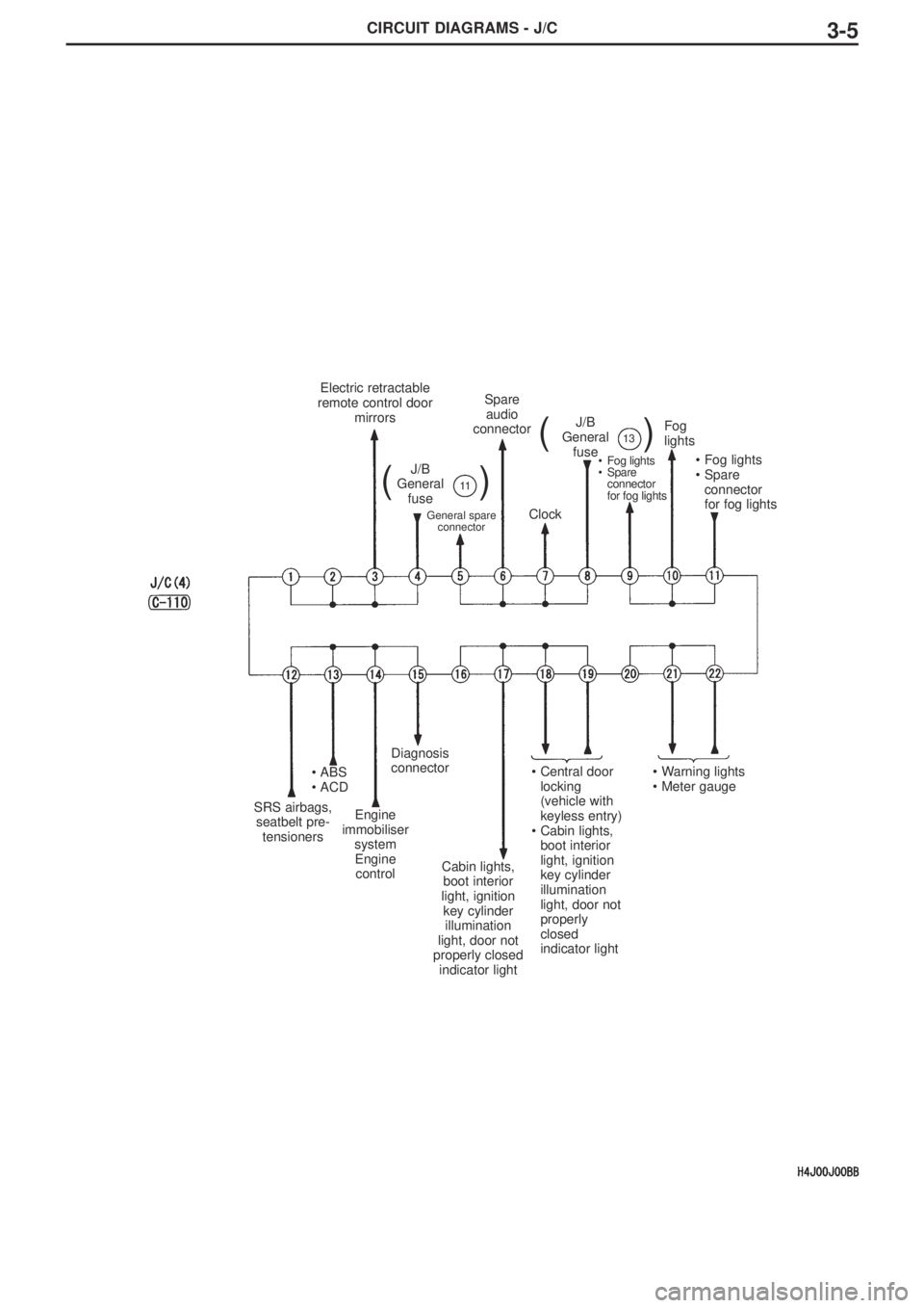
CIRCUIT DIAGRAMS - J/C3-5
Electric retractable
remote control door
mirrors
J/B
General
fuse
()11
J/B
General
fuse
()13
General spare
connector
Spare
audio
connector
Clock
•Fog lights
•Spare
connector
for fog lights
Fog
lights
•Fog lights
•Spare
connector
for fog lights
SRS airbags,
seatbelt pre-
tensioners
•ABS
•ACD
Engine
immobiliser
system
Engine
control
Diagnosis
connector
Cabin lights,
boot interior
light, ignition
key cylinder
illumination
light, door not
properly closed
indicator light
•Central door
locking
(vehicle with
keyless entry)
•Cabin lights,
boot interior
light, ignition
key cylinder
illumination
light, door not
properly
closed
indicator light•Warning lights
•Meter gauge
Page 116 of 166
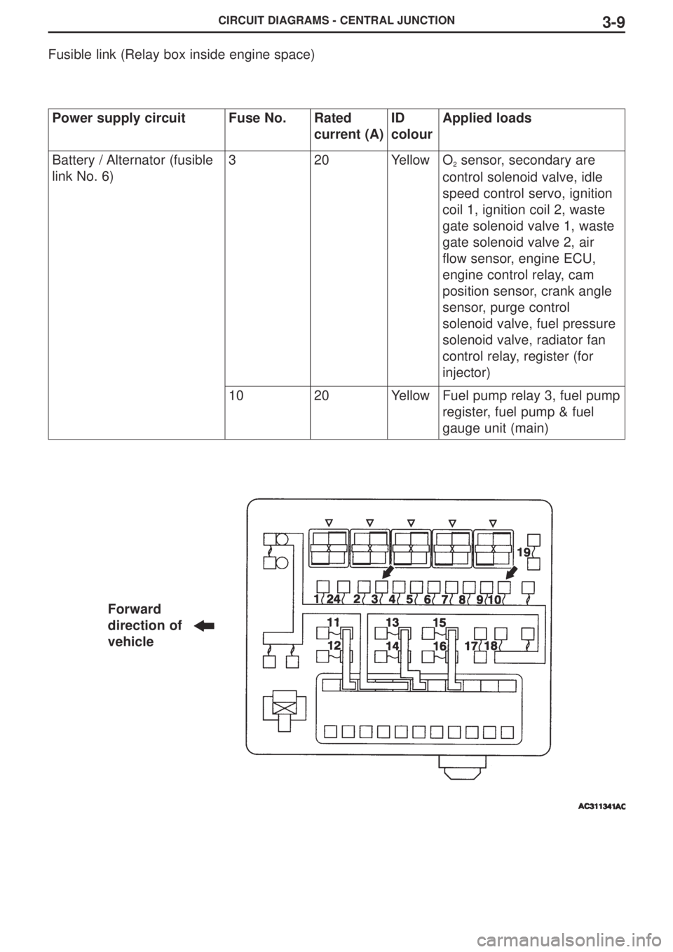
CIRCUIT DIAGRAMS - CENTRAL JUNCTION3-9
Fusible link (Relay box inside engine space)
Power supply circuitFuse No.Rated
current (A)ID
colourApplied loads
Battery / Alternator (fusible
link No. 6)320YellowO2sensor, secondary are
control solenoid valve, idle
speed control servo, ignition
coil 1, ignition coil 2, waste
gate solenoid valve 1, waste
gate solenoid valve 2, air
flow sensor, engine ECU,
engine control relay, cam
position sensor, crank angle
sensor, purge control
solenoid valve, fuel pressure
solenoid valve, radiator fan
control relay, register (for
injector)
1020YellowFuel pump relay 3, fuel pump
register, fuel pump & fuel
gauge unit (main)
Forward
direction of
vehicle
Page 117 of 166
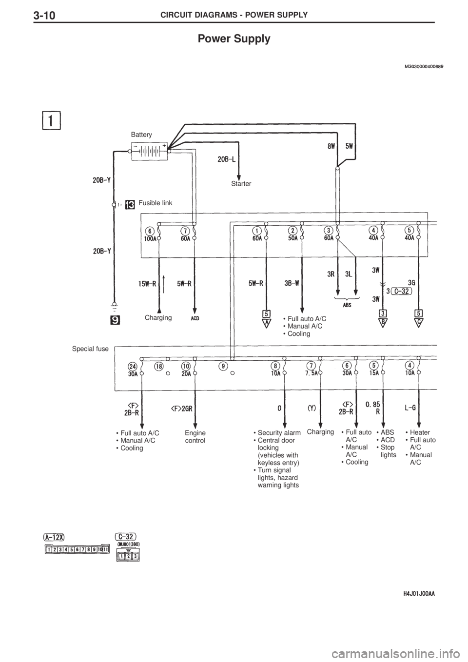
CIRCUIT DIAGRAMS - POWER SUPPLY3-10
Power Supply
Battery
Fusible link
Special fuse
Starter
Charging•Full auto A/C
•Manual A/C
•Cooling
•Full auto A/C
•Manual A/C
•CoolingEngine
control•Security alarm
•Central door
locking
(vehicles with
keyless entry)
•Turn signal
lights, hazard
warning lightsCharging•Full auto
A/C
•Manual
A/C
•Cooling•ABS
•ACD
•Stop
lights•Heater
•Full auto
A/C
•Manual
A/C
Page 119 of 166

CIRCUIT DIAGRAMS - POWER SUPPLY3-12
Power supply (cont’d)
Fusible link4
Ignition
switch
Special
fuse
Intercooler
water spray
•Engine control
•Starter
•ABS
•ACD
•SRS airbags, seat
pre-tensioners
•Ignition key reminder
buzzer
•Intercooler water
spray
•Windscreen wiper /
washer
•Warning lights
•Engine control
•Meter gauge
•Charging
•Security alarm
•Central door locking•Turn signal lights,
hazard warning lights
•Tail lights, position
lights, licence plate
lights, lighting monitor
warning buzzer
•Electric stowable
remote control door
mirrors
•Power windows
•General spare
connectors
•Fog lamps
•Headlights
•Rear wiper / washer
•Cabin lights, boot
interior light, ignition
key cylinder
illumination light, door
not properly closed
indicator lamp•SRS airbags, seatbelt
pre-tensioners
•Reversing lights
•Rear wiper / washerEngine controlIgnition
Page 121 of 166
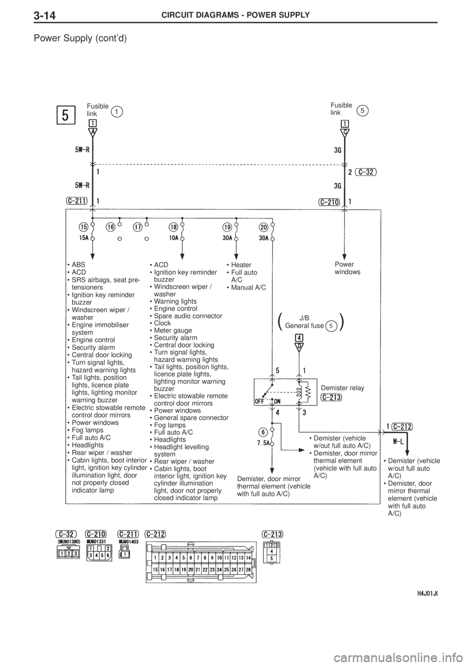
CIRCUIT DIAGRAMS - POWER SUPPLY3-14
Power Supply (cont’d)
Fusible
link1Fusible
link5
•ABS
•ACD
•SRS airbags, seat pre-
tensioners
•Ignition key reminder
buzzer
•Windscreen wiper /
washer
•Engine immobiliser
system
•Engine control
•Security alarm
•Central door locking
•Turn signal lights,
hazard warning lights
•Tail lights, position
lights, licence plate
lights, lighting monitor
warning buzzer
•Electric stowable remote
control door mirrors
•Power windows
•Fog lamps
•Full auto A/C
•Headlights
•Rear wiper / washer
•Cabin lights, boot interior
light, ignition key cylinder
illumination light, door
not properly closed
indicator lamp•ACD
•Ignition key reminder
buzzer
•Windscreen wiper /
washer
•Warning lights
•Engine control
•Spare audio connector
•Clock
•Meter gauge
•Security alarm
•Central door locking
•Turn signal lights,
hazard warning lights
•Tail lights, position lights,
licence plate lights,
lighting monitor warning
buzzer
•Electric stowable remote
control door mirrors
•Power windows
•General spare connector
•Fog lamps
•Full auto A/C
•Headlights
•Headlight levelling
system
•Rear wiper / washer
•Cabin lights, boot
interior light, ignition key
cylinder illumination
light, door not properly
closed indicator lamp•Heater
•Full auto
A/C
•Manual A/CPower
windows
J/B
General fuse()5
Demister relay
Demister, door mirror
thermal element (vehicle
with full auto A/C)
•Demister (vehicle
w/out full auto A/C)
•Demister, door mirror
thermal element
(vehicle with full auto
A/C)
•Demister (vehicle
w/out full auto
A/C)
•Demister, door
mirror thermal
element (vehicle
with full auto
A/C)
Page 123 of 166
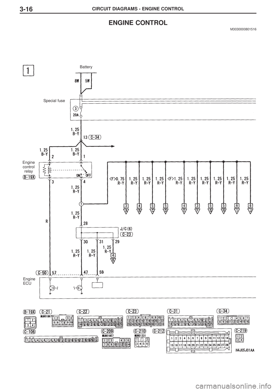
CIRCUIT DIAGRAMS - ENGINE CONTROL3-16
ENGINE CONTROL
M3030000801516
Battery
Special fuse
Engine
control
relay
Engine
ECU
Page 129 of 166
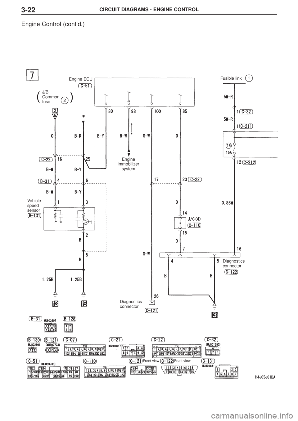
CIRCUIT DIAGRAMS - ENGINE CONTROL3-22
Engine Control (cont’d.)
J/B
Common
fuse
()2
Fusible link1Engine ECU
Vehicle
speed
sensor
Engine
immobilizer
system
Diagnostics
connector
Diagnostics
connector
Front viewFront view
Page 131 of 166
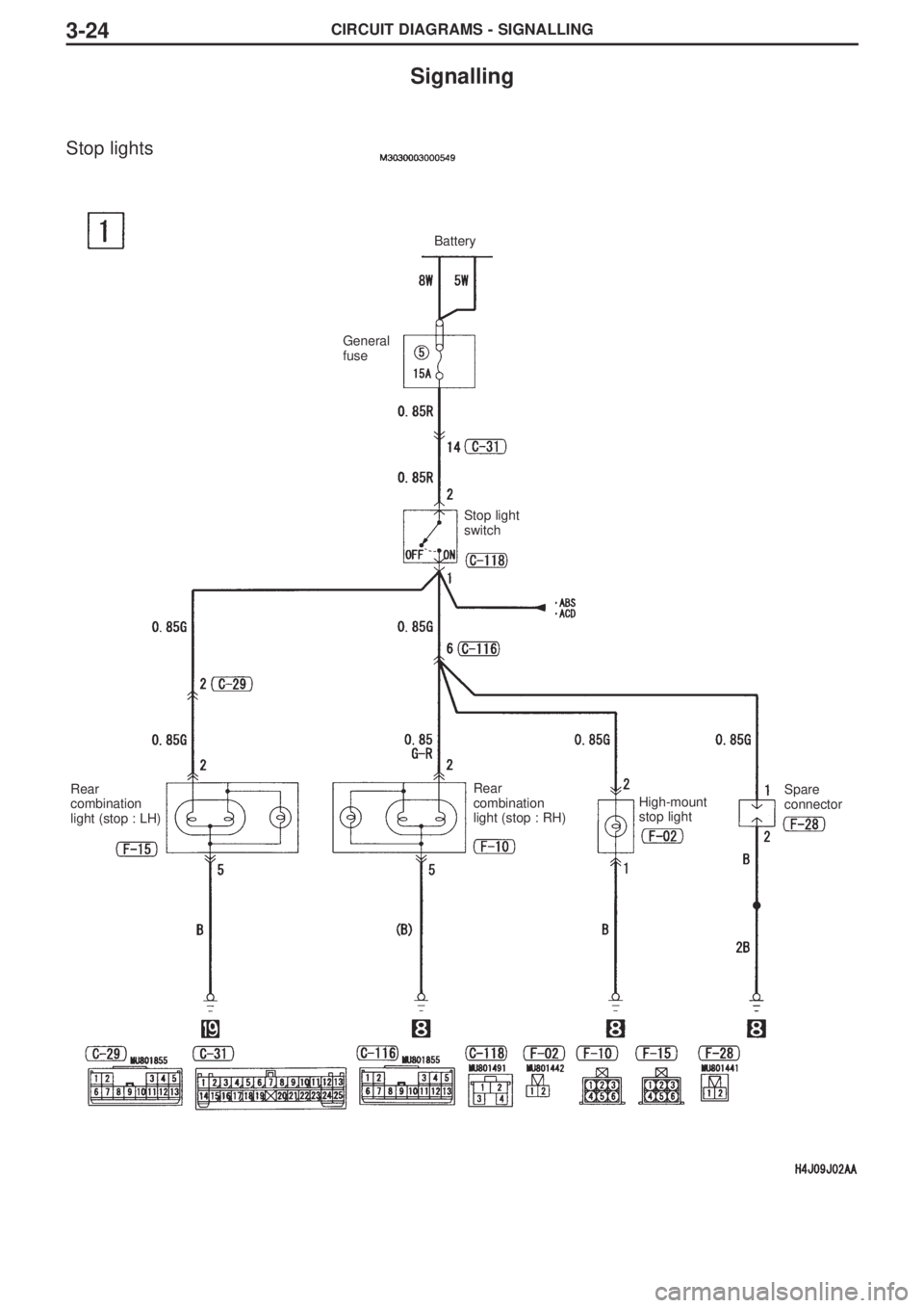
CIRCUIT DIAGRAMS - SIGNALLING3-24
Signalling
Stop lights
Battery
General
fuse
Stop light
switch
Rear
combination
light (stop : LH)Rear
combination
light (stop : RH)High-mount
stop lightSpare
connector