MITSUBISHI LANCER IX 2006 User Guide
LANCER IX 2006
MITSUBISHI
MITSUBISHI
https://www.carmanualsonline.info/img/19/57327/w960_57327-0.png
MITSUBISHI LANCER IX 2006 User Guide
Page 270 of 800
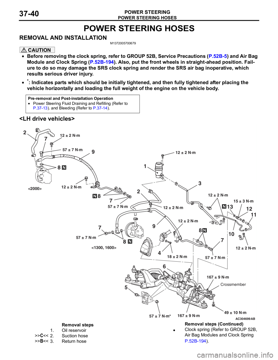
POWER STEERING HOSES
POWER STEERING37-40
POWER STEERING HOSES
REMOVAL AND INSTALLATIONM1372005700679
CAUTION
•Before removing the clock spring, refer to GROUP 52B, Service Precautions (P.52B-5) and Air Bag
Module and Clock Spring (P.52B-194). Also, put the front wheels in straight-ahead position. Fail-
ure to do so may damage the SRS clock spring and render the SRS air bag inoperative, which
results serious driver injury.
•
Pre-removal and Post-installation Operation
•Power Steering Fluid Draining and Refilling (Refer to P.37-13). and Bleeding (Refer to P.37-14).
*: Indicates parts which should be initially tightened, and then fully tightened after placing the
vehicle horizontally and loading the full weight of the engine on the vehicle body.
AC304699AB
15 ± 3 N·m
18 ± 2 N·m
167 ± 9 N·m
12 ± 2 N·m
49 ± 10 N·m
12 ± 2 N·m
57 ± 7 N·m*57 ± 7 N·m
3
1
2
9
1310
7 11
12
5 68
12 ± 2 N·m
12 ± 2 N·m
2
9
4
7
8
7
8
7
8
57 ± 7 N·m57 ± 7 N·m
57 ± 7 N·m
12 ± 2 N·m
167 ± 9 N·mCrossmember
12 ± 2 N·m
<1300, 1600>
<2000>
12 ± 2 N·m
Removal steps
1.Oil reservoir
>>C<<2.Suction hose
>>B<<3.Return hose
•Clock spring (Refer to GROUP 52B,
Air Bag Modules and Clock Spring
P.52B-194).
Removal steps (Continued)
Page 423 of 800
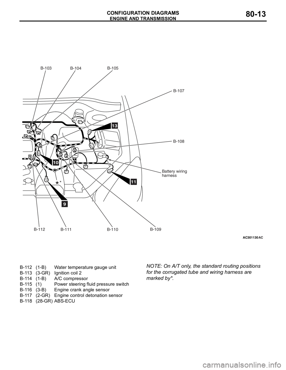
AC301130AC
9
10
11
13
B-103B-104 B-105
B-107
B-108
Battery wiring
harness
B-109
B-110
B-111
*
B-112
B-112(1-B)Water temperature gauge unit
B-113(3-GR)Ignition coil 2
B-114(1-B)A/C compressor
B-115(1)Power steering fluid pressure switch
B-116(3-B)Engine crank angle sensor
B-117(2-GR)Engine control detonation sensor
B-118(28-GR)ABS-ECU
ENGINE AND TRA
N SMISSION
CONF IGURA TION D I A G RA MS80-13
NOTE: On A/T only , the st andard routing positions
for the
corrug a ted tu be and wiring harne ss are
marked by*.
Page 427 of 800
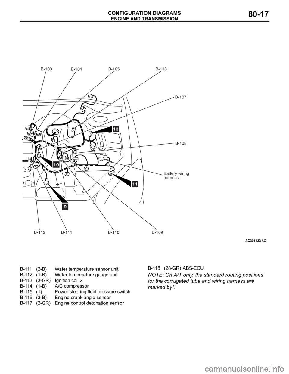
AC301133AC
9
10
11
13
B-103B-104 B-105
B-107
B-108
Battery wiring
harness
B-109
B-110
B-111
*
B-112
B-118
B-111(2-B)Water temperature sensor unit
B-112(1-B)Water temperature gauge unit
B-113(3-GR)Ignition coil 2
B-114(1-B)A/C compressor
B-115(1)Power steering fluid pressure switch
B-116(3-B)Engine crank angle sensor
B-117(2-GR)Engine control detonation sensor
B-118(28-GR)ABS-ECU
ENGINE AND TRA
N SMISSION
CONF IGURA TION D I A G RA MS80-17
NOTE: On A/T only , the st andard routing positions
for the
corrug a ted tu be and wiring harne ss are
marked by*.
Page 431 of 800
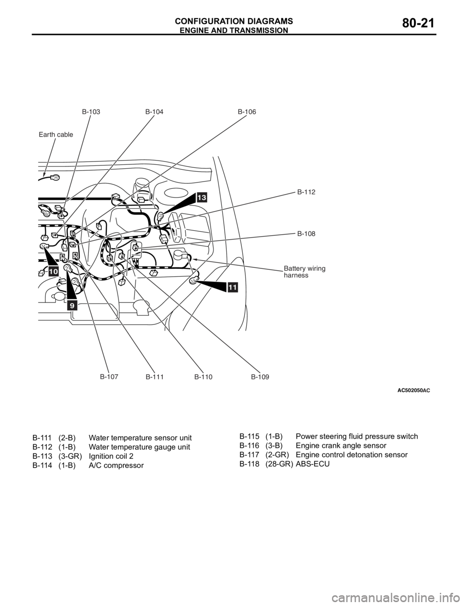
AC502050AC
9
10
11
13
B-103B-104
B-106
B-112B-108
Battery wiring
harness
B-111
B-110B-107
Earth cable
B-109
B-111(2-B)Water temperature sensor unit
B-112(1-B)Water temperature gauge unit
B-113(3-GR)Ignition coil 2
B-114(1-B)A/C compressor
B-115(1-B)Power steering fluid pressure switch
B-116(3-B)Engine crank angle sensor
B-117(2-GR)Engine control detonation sensor
B-118(28-GR)ABS-ECU
ENGINE AND TRA N SMISSION
CONF IGURA TION D I A G RA MS80-21
Page 435 of 800
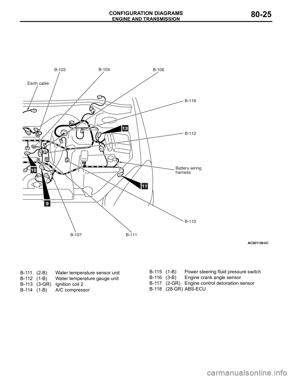
AC301139AC
9
11
13
B-103B-106
B-118
B-112
Battery wiring
harness
B-110
B-111
B-107
B-104
10
Earth cable
B-111(2-B)Water temperature sensor unit
B-112(1-B)Water temperature gauge unit
B-113(3-GR)Ignition coil 2
B-114(1-B)A/C compressor
B-115(1-B)Power steering fluid pressure switch
B-116(3-B)Engine crank angle sensor
B-117(2-GR)Engine control detonation sensor
B-118(28-GR)ABS-ECU
ENGINE AND TRA N SMISSION
CONF IGURA TION D I A G RA MS80-25
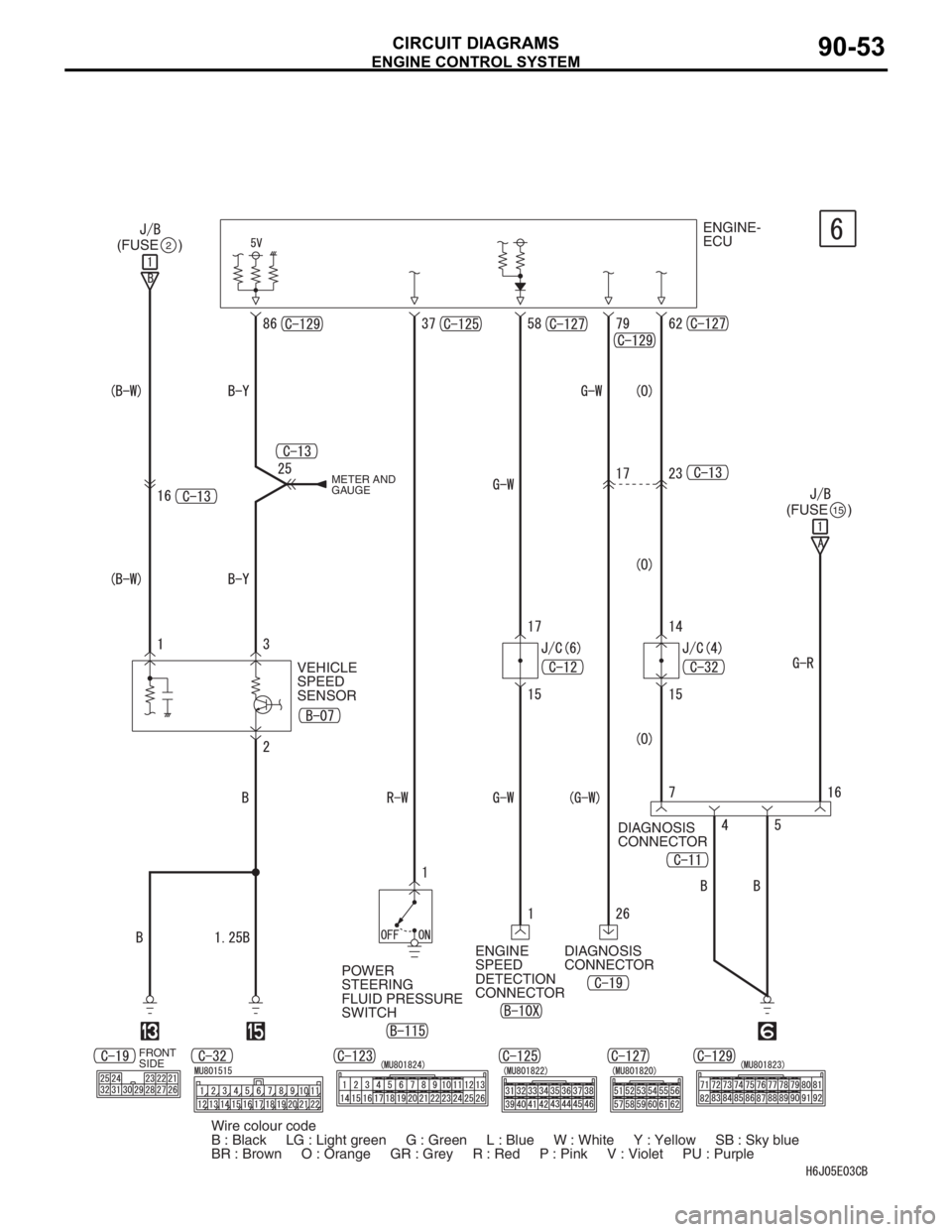
Page 517 of 800
ENGINE CONTROL SYSTEM
CIRCUIT DIAGRAMS90-53
ENGINE-
ECU
(FUSE )
2
(FUSE )15
DIAGNOSIS
CONNECTOR
DIAGNOSIS
CONNECTOR
POWER
STEERING
FLUID PRESSURE
SWITCHENGINE
SPEED
DETECTION
CONNECTOR VEHICLE
SPEED
SENSOR
METER AND
GAUGE
FRONT
SIDE
Wire colour code
B : Black LG : Light green G : Green L : Blue W : White Y : Yellow SB : Sky blue
BR : Brown O : Orange GR : Grey R : Red P : Pink V : Violet PU : Purple
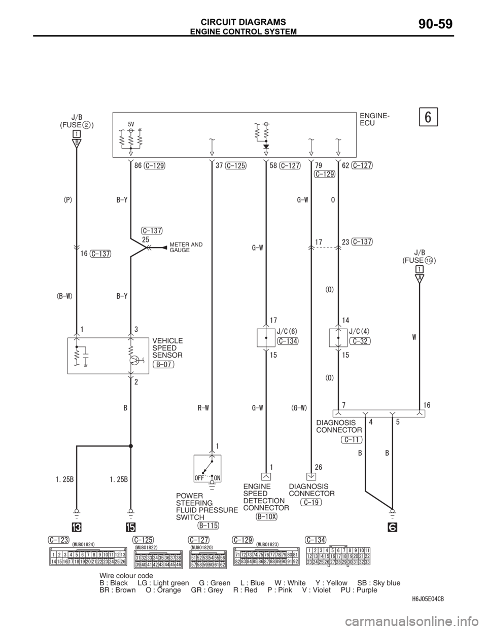
Page 523 of 800
ENGINE CONTROL SYSTEM
CIRCUIT DIAGRAMS90-59
ENGINE-
ECU
(FUSE )
2
(FUSE )15
DIAGNOSIS
CONNECTOR
DIAGNOSIS
CONNECTOR
POWER
STEERING
FLUID PRESSURE
SWITCHENGINE
SPEED
DETECTION
CONNECTOR VEHICLE
SPEED
SENSOR
METER AND
GAUGE
Wire colour code
B : Black LG : Light green G : Green L : Blue W : White Y : Yellow SB : Sky blue
BR : Brown O : Orange GR : Grey R : Red P : Pink V : Violet PU : Purple
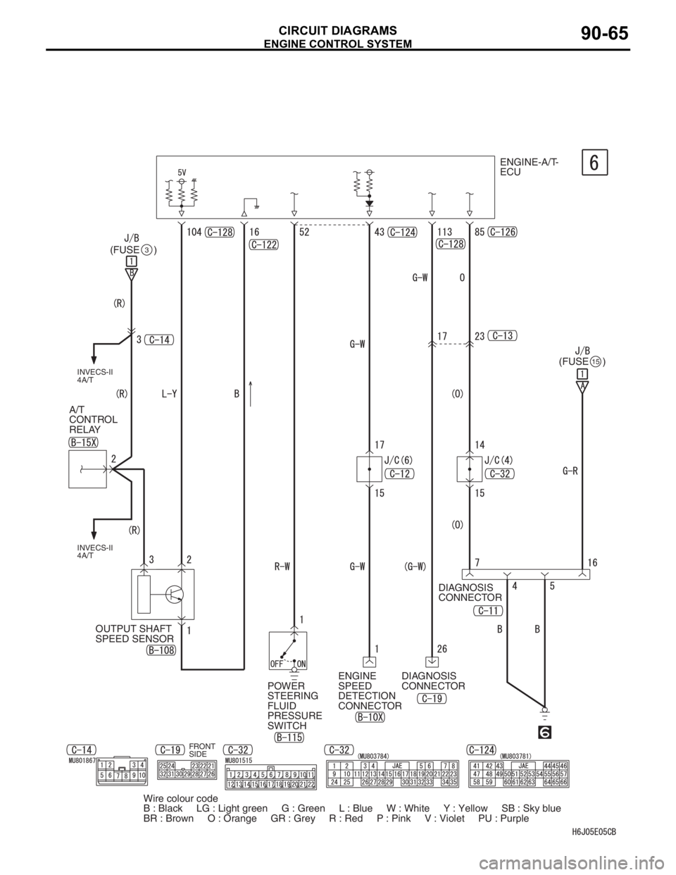
Page 529 of 800
ENGINE CONTROL SYSTEM
CIRCUIT DIAGRAMS90-65
FRONT
SIDE
ENGINE-A/T-
ECU
(FUSE )
3
(FUSE )15
DIAGNOSIS
CONNECTOR
DIAGNOSIS
CONNECTOR ENGINE
SPEED
DETECTION
CONNECTOR OUTPUT SHAFT
SPEED SENSOR A/T
CONTROL
RELAY
INVECS-II
4A/T INVECS-II
4A/T
POWER
STEERING
FLUID
PRESSURE
SWITCH
Wire colour code
B : Black LG : Light green G : Green L : Blue W : White Y : Yellow SB : Sky blue
BR : Brown O : Orange GR : Grey R : Red P : Pink V : Violet PU : Purple
Page 535 of 800
ENGINE CONTROL SYSTEM
CIRCUIT DIAGRAMS90-71
ENGINE-A/T-
ECU
(FUSE )
(FUSE )
DIAGNOSIS
CONNECTOR
DIAGNOSIS
CONNECTOR
POWER
STEERING
FLUID PRESSURE
SWITCHENGINE
SPEED
DETECTION
CONNECTOR OUTPUT SHAFT
SPEED SENSOR A/T
CONTROL
RELAY
INVECS-II
4A/T INVECS-II
4A/T
3
15
Wire colour code
B : Black LG : Light green G : Green L : Blue W : White Y : Yellow SB : Sky blue
BR : Brown O : Orange GR : Grey R : Red P : Pink V : Violet PU : Purple
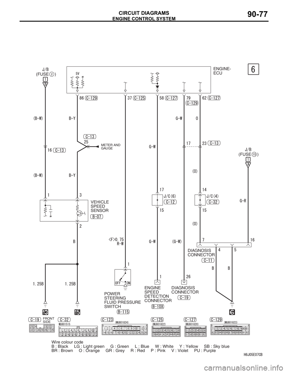
Page 541 of 800
ENGINE CONTROL SYSTEM
CIRCUIT DIAGRAMS90-77
ENGINE-
ECU
(FUSE )
2
(FUSE )15
DIAGNOSIS
CONNECTOR
DIAGNOSIS
CONNECTOR
POWER
STEERING
FLUID PRESSURE
SWITCHENGINE
SPEED
DETECTION
CONNECTOR VEHICLE
SPEED
SENSOR
METER AND
GAUGE
FRONT
SIDE
Wire colour code
B : Black LG : Light green G : Green L : Blue W : White Y : Yellow SB : Sky blue
BR : Brown O : Orange GR : Grey R : Red P : Pink V : Violet PU : Purple

