throttle MITSUBISHI LANCER IX 2006 User Guide
[x] Cancel search | Manufacturer: MITSUBISHI, Model Year: 2006, Model line: LANCER IX, Model: MITSUBISHI LANCER IX 2006Pages: 800, PDF Size: 45.03 MB
Page 118 of 800
Battery voltageNormal condition
AppliedVacuum leaks
Not appliedVacuum maintained
EMISSION CONTROL
ENGINE AND EMISSION CONTROL17-12
5. Measure the resistance between the terminals of the solenoid valve.
Standard value: 30 − 34 Ω (at 20°C)
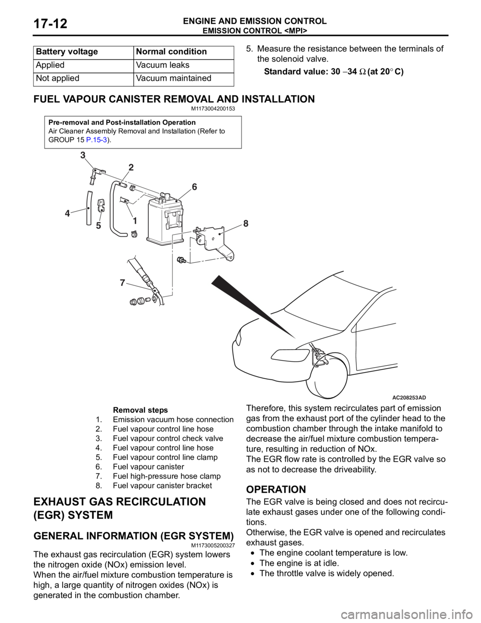
FUEL VAPOUR CANISTER RE MOVAL AND INSTALLATION
M1173004200153
Pre-removal and Post-installation Operation
Air Cleaner Assembly Removal and Installation (Refer to
GROUP 15
P.15-3).
AC208253
1
2
3
4 5 6
7 8
AD
Removal steps
1.Emission vacuum hose connection
2.Fuel vapour control line hose
3.Fuel vapour control check valve
4.Fuel vapour control line hose
5.Fuel vapour control line clamp
6.Fuel vapour canister
7.Fuel high-pressure hose clamp
8.Fuel vapour canister bracket
EXHAUST GAS RECIRCULA
T ION
(EGR) SYSTEM
GENERAL INFORMAT ION (EGR SYSTEM)
M1173 0052 0032 7
The exhaust gas recircu l atio n (EGR) system lowers
the nitrogen
oxide (NOx) emission level.
When the air/fuel mixture combus tio n temp erature is
high,
a larg e qua ntity of nitrogen oxides (NOx) is
generat
ed in the comb ustion chamb e r .
Therefor e, this syst em re circulat es p a rt o f emission
gas fro
m the e x ha ust po rt of the cylinder h ead to th e
combust
i on chamber thro ugh th e int a ke ma nifold to
decre
ase the air/fuel mixture combust i on te mpera
-
ture, resulting in redu ctio n of NOx.
The EGR flow rate is cont rolle d by the EGR valve so
as no
t to de crease the driveability .
OPERAT ION
The EGR valve is being clos ed an d does not re circu-
late ex hau st ga ses unde r one o f the fo llo wing condi-
tions.
Otherwise, th e EGR va lve is opene d an d recircul ates
exha
ust g a ses.
•The engine coolan t temperature is low .
•The engine is at idle.
•The throttle va lve is widely ope ned.
Page 121 of 800
EMISSION CONTROL
ENGINE AND EMISSION CONTROL17-15
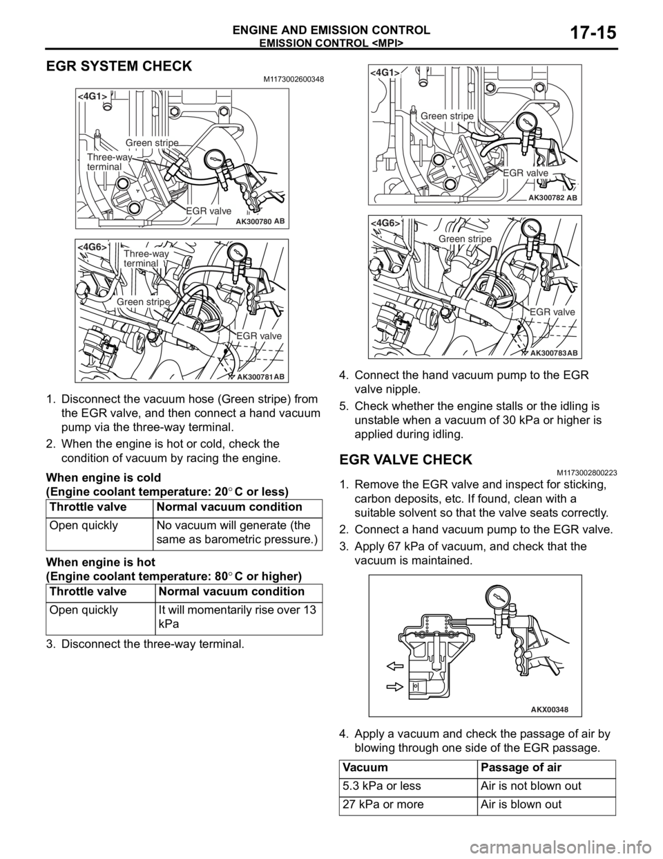
EGR SYSTEM CHECK
M1173002600348
AK300780AB
<4G1>
EGR valve
Green stripe
Three-way
terminal
AK300781AB
<4G6>
EGR valve
Green stripe
Three-way
terminal
1.Disco nnect the vacu um ho se (Green stripe) from
th e EGR valve, a nd th en connect a hand vacuum
pu mp via t he thre e-way te rmin al.
2.Wh en the engine is hot o r cold, check the
condition of va cuum by racing the engine.
When engine is c o ld
(Eng ine coo lant tem perature: 20°C or less)
Throttle valveNormal vacuum co ndition
Open quicklyNo va cuum will gene rate (th e
same as baro
m etric pre s sure.)
When engine is h o t
(Eng ine coo lant tem perature: 80°C or higher)
Throttle valveNormal vacuum c ondition
Open quicklyIt will mo me nt a r i l y rise o v er 13
kPa
3.Disco nnect the th ree-way t e rminal.
AK300782AB
<4G1>
EGR valve
Green stripe
AK300783AB
<4G6>
EGR valve
Green stripe
4.Conn ect the han d va cuum pump to t he EGR
valve nipple.
5.Check whe t her th e engine st alls or the idling is
u n st able when a vacuum of 30 kPa or h i gher is
a pplied during idling.
EGR V A L V E CHECKM1173 0028 0022 3
1.Remove the EGR valve an d inspect for stickin g ,
carbon deposit s, e t c. If found , clean with a
suit able so lve n t so that th e va lve seat s corre ctly .
2.Conn ect a hand vacuum pump to the EGR va lve .
3.App l y 6 7 kPa of va cuum, and check t hat the
vacu um is maint a ined.
AKX00348
4.App l y a vacuum and chec k th e p a ssage of air by
b l owing throug h one side of the EGR p a ssage.
VacuumPassage of air
5.3 kPa or lessAir is not blown out
27 kPa or moreAir is blown out
Page 396 of 800
SENSOR
COMPONENT LOCATIONS70-6
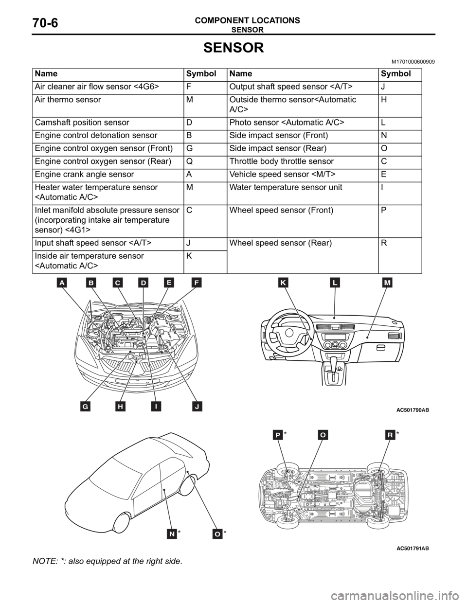
SENSOR
M1701000600909
NameSymbolNameSymbol
Air cleaner air flow sensor <4G6>FOutput shaft speed sensor J
Air thermo sensorMOutside thermo sensor
Camshaft position sensorDPhoto sensor
Engine control detonation sensorBSide impact sensor (Front)N
Engine control oxygen sensor (Front)GSide impact sensor (Rear)O
Engine control oxygen sensor (Rear)QThrottle body throttle sensorC
Engine crank angle sensorAVehicle speed sensor
Heater water temperature sensor
Inlet manifold absolute pressure sensor
(incorporating intake air temperature
sensor) <4G1>CWheel speed sensor (Front)P
Input shaft speed sensor JWheel speed sensor (Rear)R
Inside air temperature sensor
AC501790
BDCFEA
GHIJ
MKL
AB
AC501791AB
NO
POR
** *
*
NO
TE: *: also eq uipp ed at t he rig h t side.
Page 397 of 800
AC208762
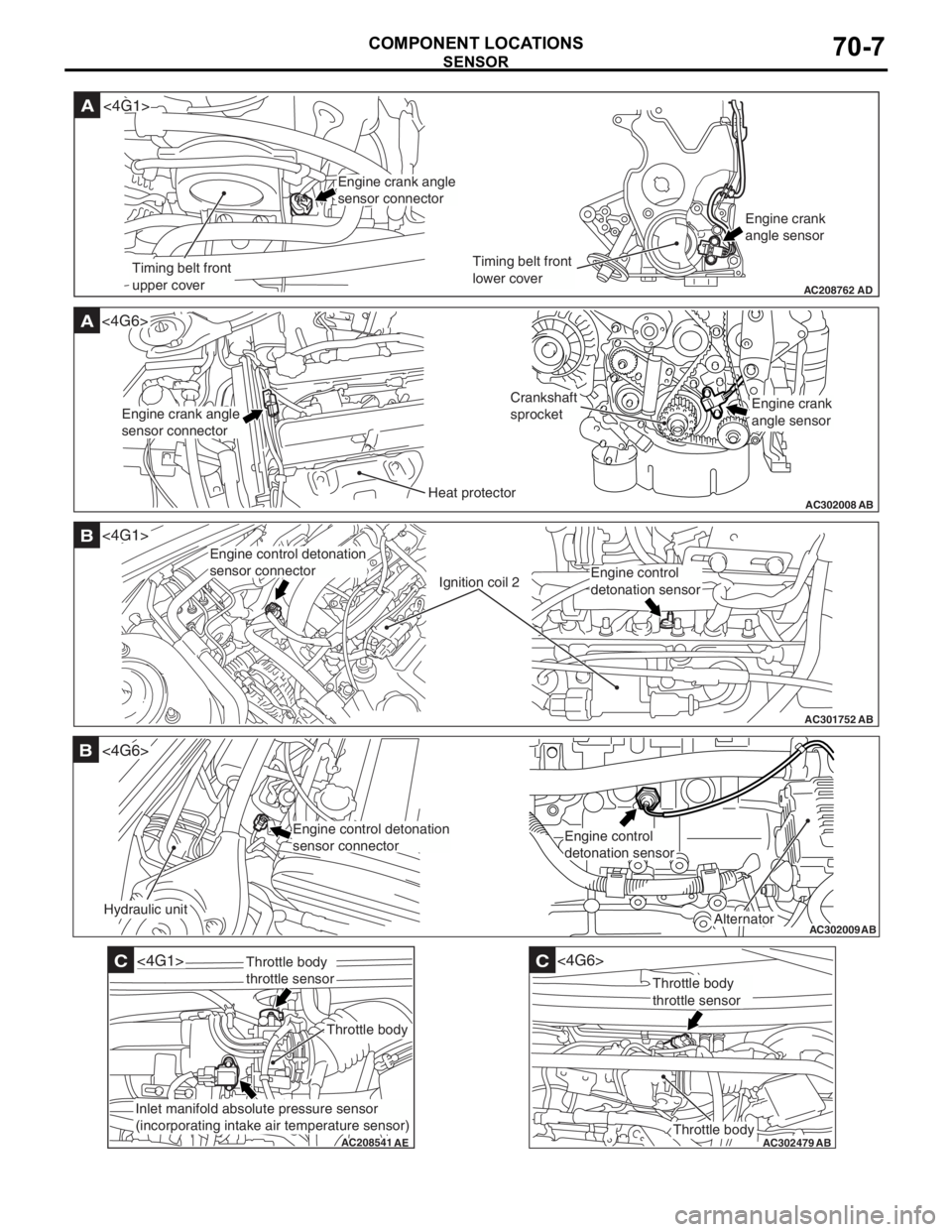
A
AD
Timing belt front
upper coverTiming belt front
lower coverEngine crank
angle sensor
<4G1>
Engine crank angle
sensor connector
AC302008
A<4G6>
ABHeat protector
Crankshaft
sprocket
Engine crank angle
sensor connectorEngine crank
angle sensor
AC301752
B
AB
Ignition coil 2
<4G1>
Engine control detonation
sensor connector
Engine control
detonation sensor
AC302009
B
AB
Hydraulic unit
<4G6>
Alternator
Engine control detonation
sensor connectorEngine control
detonation sensor
AC208541
C
AE
<4G1>
Throttle body
Throttle body
throttle sensor
Inlet manifold absolute pressure sensor
(incorporating intake air temperature sensor)
AC302479
AB
C
Throttle body
<4G6>
Throttle body
throttle sensor
SENSOR
COMPONENT LOCA TIONS70-7
Page 402 of 800
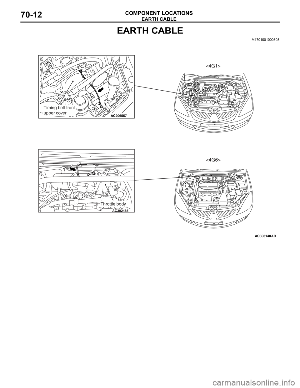
EARTH CABLE
COMPONENT LOCATIONS70-12
EARTH CABLE
M1701001000308
AC303148
AC206557
AC302485
AB
Timing belt front
upper cover
Throttle body
<4G1><4G6>
Page 420 of 800
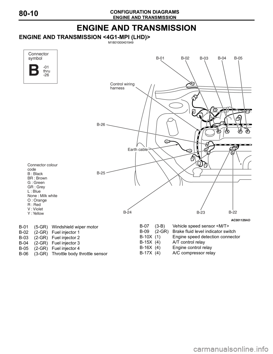
ENGINE AND TRANSMISSION
CONFIGURATION DIAGRAMS80-10
ENGINE AND TRANSMISSION
ENGINE AND TRANSMISSION <4G1-MPI (LHD)>M1801000401949
AC301129
AD
B-02
B-03B-04B-05
B-22
B-23
B-24
B-25
B-26
Control wiring
harnessB-01
Connector colour
code
B : Black
BR : Brown
G : Green
GR : Grey
L : Blue
None : Milk white
O : Orange
R : Red
V : Violet
Y : Yellow*
Connector
symbol
-01
thru
-26
B
Earth cable
B-01(5-GR)Windshield wiper motor
B-02(2-GR)Fuel injector 1
B-03(2-GR)Fuel injector 2
B-04(2-GR)Fuel injector 3
B-05(2-GR)Fuel injector 4
B-06(3-GR)Throttle body throttle sensor
B-07(3-B)Vehicle speed sensor
B-09(2-GR)Brake fluid level indicator switch
B-10X(1)Engine speed detection connector
B-15X(4)A/T control relay
B-16X(4)Engine control relay
B-17X(4)A/C compressor relay
Page 422 of 800
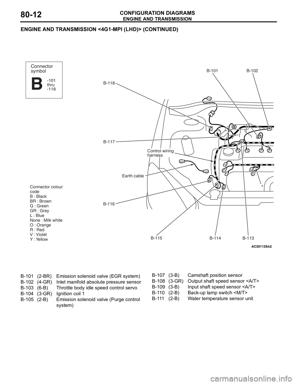
ENGINE AND TRANSMISSION
CONFIGURATION DIAGRAMS80-12
ENGINE AND TRANSMISSION <4G1-MPI (LHD)> (CONTINUED)
AC301129AE
B-118B-101 B-102
B-113
B-114
B-115
B-116 B-117
Earth cable
Control wiring
harness
Connector colour
code
B : Black
BR : Brown
G : Green
GR : Grey
L : Blue
None : Milk white
O : Orange
R : Red
V : Violet
Y : Yellow
Connector
symbol
-101
thru
-118
B
*
B-101(2-BR)Emission solenoid valve (EGR system)
B-102(4-GR)Inlet manifold absolu te pressure sensor
B-103(6-B)Throttle body idle speed control servo
B-104(3-GR)Ignition coil 1
B-105(2-B)Emission solenoid va lve (Purge control
system)
B-107(3-B)Camshaft position sensor
B-108(3-GR)Output shaft speed sensor
B-109(3-B)Input shaft speed sensor
B-110(2-B)Back-up lamp switch
B-111(2-B)Water temperature sensor unit
Page 424 of 800
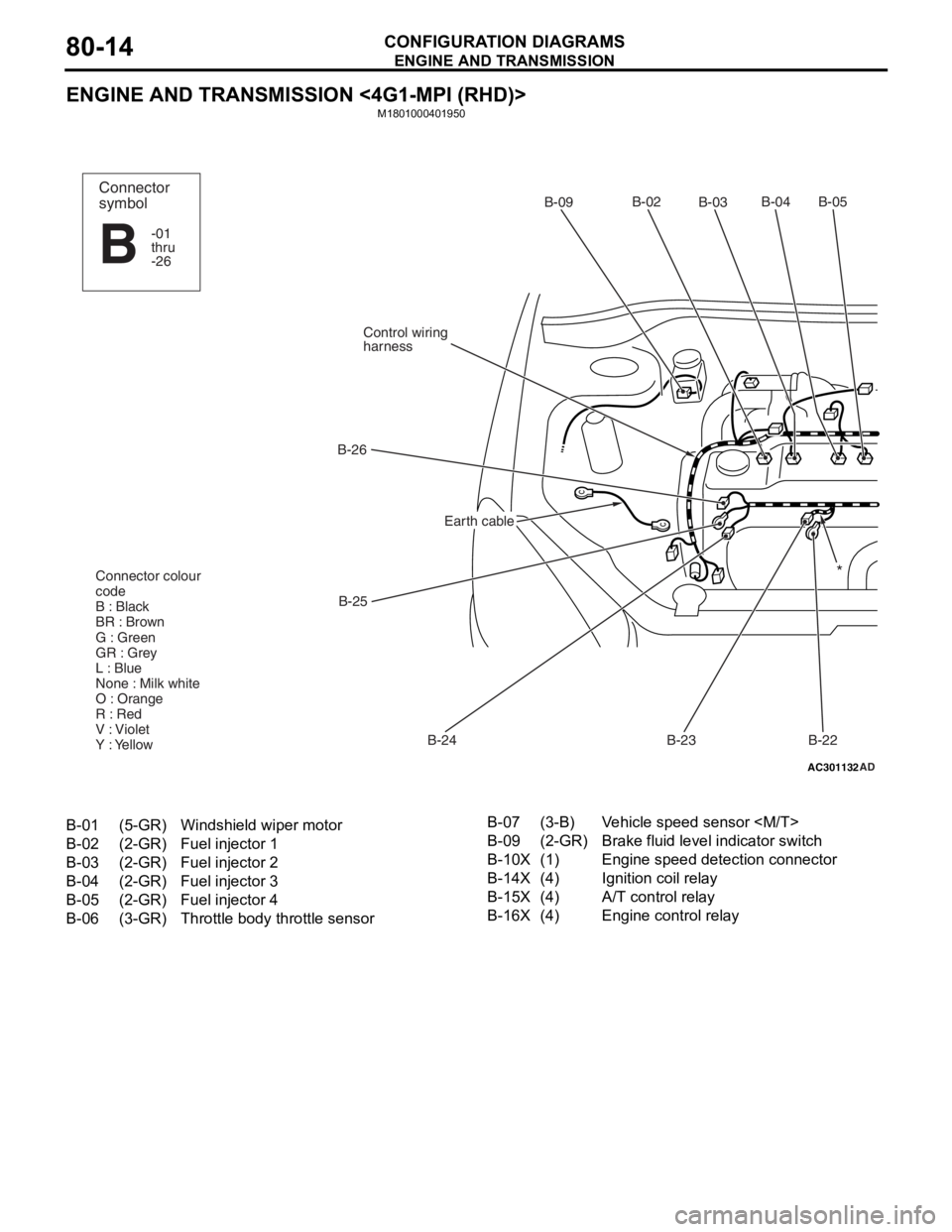
ENGINE AND TRANSMISSION
CONFIGURATION DIAGRAMS80-14
ENGINE AND TRANSMISSION <4G1-MPI (RHD)>
M1801000401950
AC301132AD
B-02
B-03B-04 B-05
B-22
B-23
B-24
B-25
B-26
Control wiring
harnessB-09
Connector colour
code
B : Black
BR : Brown
G : Green
GR : Grey
L : Blue
None : Milk white
O : Orange
R : Red
V : Violet
Y : Yellow*
Connector
symbol
-01
thru
-26
B
Earth cable
B-01(5-GR)Windshield wiper motor
B-02(2-GR)Fuel injector 1
B-03(2-GR)Fuel injector 2
B-04(2-GR)Fuel injector 3
B-05(2-GR)Fuel injector 4
B-06(3-GR)Throttle body throttle sensor
B-07(3-B)Vehicle speed sensor
B-09(2-GR)Brake fluid level indicator switch
B-10X(1)Engine speed detection connector
B-14X(4)Ignition coil relay
B-15X(4)A/T control relay
B-16X(4)Engine control relay
Page 426 of 800
ENGINE AND TRANSMISSION
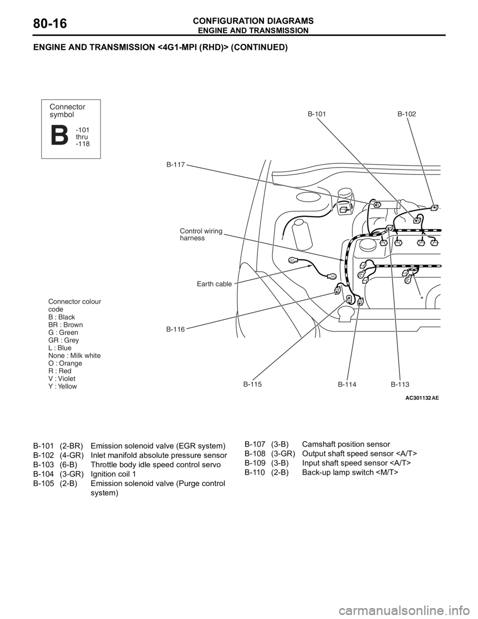
CONFIGURATION DIAGRAMS80-16
ENGINE AND TRANSMISSION <4G1-MPI (RHD)> (CONTINUED)
AC301132AE
B-117B-101 B-102
B-113
B-114
B-115
B-116
Earth cable
Control wiring
harness
Connector colour
code
B : Black
BR : Brown
G : Green
GR : Grey
L : Blue
None : Milk white
O : Orange
R : Red
V : Violet
Y : Yellow
Connector
symbol
-101
thru
-118
B
*
B-101(2-BR)Emission solenoid valve (EGR system)
B-102(4-GR)Inlet manifold absolu te pressure sensor
B-103(6-B)Throttle body idle speed control servo
B-104(3-GR)Ignition coil 1
B-105(2-B)Emission solenoid va lve (Purge control
system)
B-107(3-B)Camshaft position sensor
B-108(3-GR)Output shaft speed sensor
B-109(3-B)Input shaft speed sensor
B-110(2-B)Back-up lamp switch
Page 428 of 800
ENGINE AND TRANSMISSION
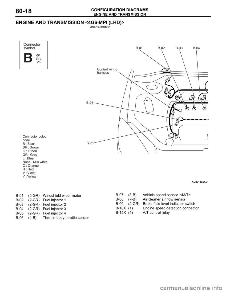
CONFIGURATION DIAGRAMS80-18
ENGINE AND TRANSMISSION <4G6-MPI (LHD)>
M1801000401961
AC301135AD
B-02
B-03B-04
B-25
B-26
Control wiring
harnessB-01
Connector colour
code
B : Black
BR : Brown
G : Green
GR : Grey
L : Blue
None : Milk white
O : Orange
R : Red
V : Violet
Y : YellowConnector
symbol
-01
thru
-26
B
B-01(5-GR)Windshield wiper motor
B-02(2-GR)Fuel injector 1
B-03(2-GR)Fuel injector 2
B-04(2-GR)Fuel injector 3
B-05(2-GR)Fuel injector 4
B-06(4-B)Throttle body throttle sensor
B-07(3-B)Vehicle speed sensor
B-08(7-B)Air cleaner air flow sensor
B-09(2-GR)Brake fluid level indicator switch
B-10X(1)Engine speed detection connector
B-15X(4)A/T control relay