weight MITSUBISHI LANCER IX 2006 User Guide
[x] Cancel search | Manufacturer: MITSUBISHI, Model Year: 2006, Model line: LANCER IX, Model: MITSUBISHI LANCER IX 2006Pages: 800, PDF Size: 45.03 MB
Page 178 of 800

CROSSMEMBER
POWER PLANT MOUNT32-8
INSTALLATION SERVICE POINTS
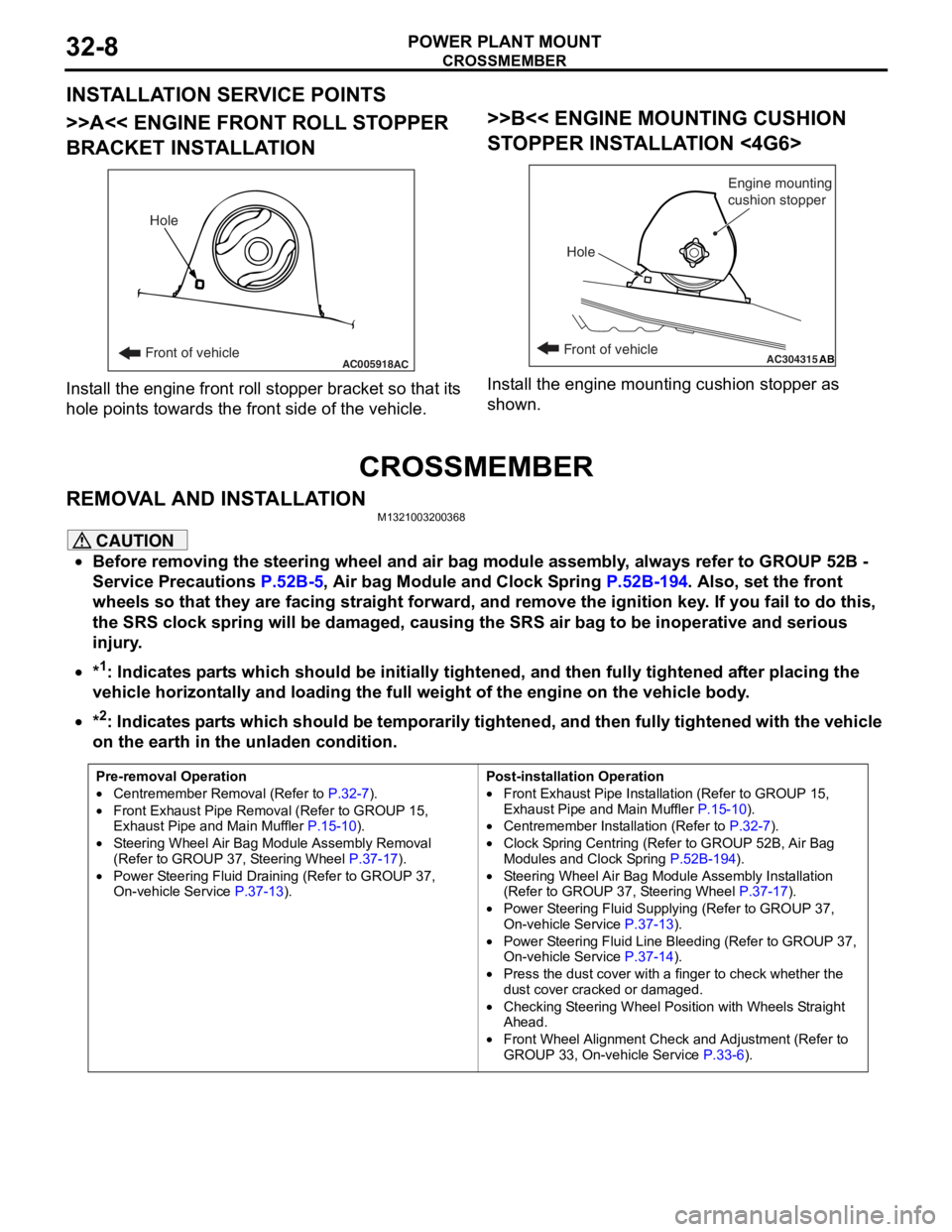
>>A<< ENGINE FRONT ROLL STOPPER
BRACKET INSTALLATION
AC005918Front of vehicleHoleAC
Inst
all th e en gine fron t roll stop per b r acket so that it s
hole
point s towards the fro n t side of the vehicle.
>>B<< ENGINE MOUNTING CUSHION
ST
OPPER INST ALLA TION <4G6>
AC304315ABFront of vehicle
Hole Engine mounting
cushion stopper
Inst
all the e ngin e mo untin g cushio n sto pper a s
shown.
CROSSMEMBER
REMOVA L AND INST ALLA TIONM13210032 0036 8
CAUTION
•Before removing the steering wheel and air bag module assembly, always refer to GROUP 52B -
Service Precautions
P.52B-5, Air bag Module and Clock Spring P.52B-194. Also, set the front
wheels so that they are facing straight forward, and remove the ignition key. If you fail to do this,
the SRS clock spring will be damaged, causing the SRS air bag to be inoperative and serious
injury.
•*1: Indicates parts which should be initially tightened, and then fully tightened after placing the
vehicle horizontally and loading the full weight of the engine on the vehicle body.
•
Pre-removal Operation
•Centremember Removal (Refer to P.32-7).
•Front Exhaust Pipe Remova l (Refer to GROUP 15,
Exhaust Pipe and Main Muffler P.15-10).
•Steering Wheel Air Bag Mo dule Assembly Removal
(Refer to GROUP 37, Steering Wheel P.37-17).
•Power Steering Fluid Draining (Refer to GROUP 37,
On-vehicle Service P.37-13).
Post-installation Operation
•Front Exhaust Pipe Installation (Refer to GROUP 15,
Exhaust Pipe and Main Muffler
P.15-10).
•Centremember Installation (Refer to P.32-7).
•Clock Spring Centring (Refer to GROUP 52B, Air Bag
Modules and Clock Spring P.52B-194).
•Steering Wheel Air Bag Module Assembly Installation
(Refer to GROUP 37, Steering Wheel P.37-17).
•Power Steering Fluid Supplying (Refer to GROUP 37,
On-vehicle Service P.37-13).
•Power Steering Fluid Line Bleeding (Refer to GROUP 37,
On-vehicle Service P.37-14).
•Press the dust cover with a finger to check whether the
dust cover cracked or damaged.
•Checking Steering Wheel Position with Wheels Straight
Ahead.
•Front Wheel Alignment Check and Adjustment (Refer to
GROUP 33, On-vehicle Service P.33-6).
*2: Indicates parts which should be temporarily tightened, and then fully tightened with the vehicle
on the earth in the unladen condition.
Page 196 of 800

STABILIZER BAR
FRONT SUSPENSION33-14
STABILIZER BAR
REMOVAL AND INSTALLATIONM1332004000673
CAUTION
•Before removing the steering wheel and air bag module assembly, refer to GROUP 52B, Service
Precautions
P.52B-5 and Air Bag Module and Clock Spring P.52B-194. Also, put the front wheels in
straight-ahead position. Failure to do so may damage the SRS clock spring and render the SRS air
bag inoperative, which results serious driver injury.
•
Pre-removal Operation
•Steering Wheel and Air Bag Module Assembly Removal
(Comfort: refer to GROUP 37, Steering Wheel
P.37-17/Sport: refer to GROUP 37, Steering Wheel P.37-18).•Clock Spring Removal (Refer to GROUP 52B, Air Bag
Modules and Clock Spring P.52B-194).
•Centermember Removal (Ref er to GROUP 32, Engine
Roll Stopper, Centermember P.32-7).
•Front Exhaust Pipe Remova l (Refer to GROUP 15,
Exhaust Pipe and Main Muffler P.15-10).
Post-installation Operation
•Front Exhaust Pipe Installation (Refer to GROUP 15,
Exhaust Pipe and Main Muffler P.15-10).•Centermember Installation (Refer to GROUP 32, Engine
Roll Stopper, Centermember P.32-7).
•Clock Spring Installation (Refer to GROUP 52B, Air Bag
Modules and Clock Spring P.52B-194).
•Steering Wheel and Air Bag Module Assembly Installation
(Comfort: refer to GROUP 37, Steering Wheel
P.37-17/Sport: refer to GROUP 37, Steering Wheel P.37-18).•Check the dust covers for cracks or damage by pushing it
with your finger.
•Checking Steering Wheel Position with Wheels Straight
Ahead
•Front Wheel Alignment Check and Adjustment (Refer to P.33-6).
AC006139 AE
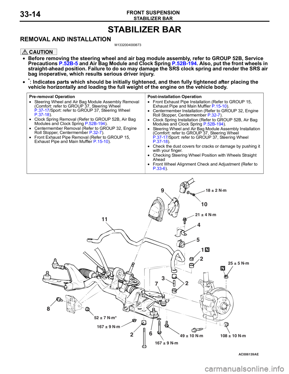
49 ± 10 N·m 108 ± 10 N·m
167 ± 9 N·m
167 ± 9 N·m
52 ± 7 N·m* 25 ± 5 N·m
21 ± 4 N·m
18 ± 2 N·m
10
9
4
5 1
2
2
3
7
6
2
11
8
*: Indicates parts which should be initially tightened, and then fully tightened after placing the
vehicle horizontally and loading the full weight of the engine on the vehicle body.
Page 233 of 800

GENERAL INFORMATION
POWER STEERING37-3
GENERAL INFORMATION
M1372000100661
Power steering has been adopted in all vehicles to
make the steering system easier to handle.
FEATURES
•A 4-spoke steering wheel is used.
•MOMO leather-wrapped 3-spoke steering wheel
is used.
•A steering column has a shock absorbing mecha-
nism and a tilt steering mechanism.
•Integral-type rack and pinion gear with high rigid-
ity and excellent response is used.
•A vane type pump with a fluid flow rate control
system which change steering effort according to
the engine speed is used.
•The separate plastic resin oil reservoir is used to
reduce weight and to make the fluid level check
-
ing easier.
SPECIFICATIONS
ItemInviteIntense
Steering
wheelTy p e4-spoke typeMOMO leather-wrapped
3-spoke type
Outside diameter mm380365
Maximum number of turns3.193.08
Steering
columnColumn mechanismShock absorbing mechanism and Tilt steering mechanism
Power steering typeIntegral type
Oil pumpTy p eVane pump
Basic discharge amount cm3/rev.7.2 <1300, 1600>
8.1 <2000>
7.2 <1300, 1600>
8.1 <2000>
Relief pressure MPa8.88.8
Reservoir typeSeparate type (plastic)
Pressure switchEquipped
Steering
gearTy p eRack and pinion
Stroke ratio (Rack stroke/Steering
wheel maximum turning radius)45.7445.74
Rack stroke mm146141
Page 270 of 800

POWER STEERING HOSES
POWER STEERING37-40
POWER STEERING HOSES
REMOVAL AND INSTALLATIONM1372005700679
CAUTION
•Before removing the clock spring, refer to GROUP 52B, Service Precautions (P.52B-5) and Air Bag
Module and Clock Spring (P.52B-194). Also, put the front wheels in straight-ahead position. Fail-
ure to do so may damage the SRS clock spring and render the SRS air bag inoperative, which
results serious driver injury.
•
Pre-removal and Post-installation Operation
•Power Steering Fluid Draining and Refilling (Refer to P.37-13). and Bleeding (Refer to P.37-14).
*: Indicates parts which should be initially tightened, and then fully tightened after placing the
vehicle horizontally and loading the full weight of the engine on the vehicle body.
AC304699AB
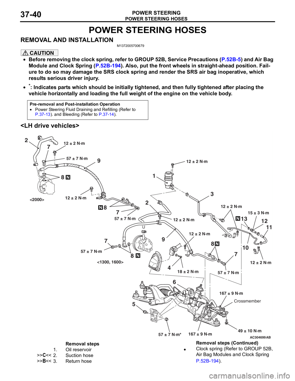
15 ± 3 N·m
18 ± 2 N·m
167 ± 9 N·m
12 ± 2 N·m
49 ± 10 N·m
12 ± 2 N·m
57 ± 7 N·m*57 ± 7 N·m
3
1
2
9
1310
7 11
12
5 68
12 ± 2 N·m
12 ± 2 N·m
2
9
4
7
8
7
8
7
8
57 ± 7 N·m57 ± 7 N·m
57 ± 7 N·m
12 ± 2 N·m
167 ± 9 N·mCrossmember
12 ± 2 N·m
<1300, 1600>
<2000>
12 ± 2 N·m
Removal steps
1.Oil reservoir
>>C<<2.Suction hose
>>B<<3.Return hose
•Clock spring (Refer to GROUP 52B,
Air Bag Modules and Clock Spring
P.52B-194).
Removal steps (Continued)