engine oil MITSUBISHI LANCER IX 2006 Owner's Manual
[x] Cancel search | Manufacturer: MITSUBISHI, Model Year: 2006, Model line: LANCER IX, Model: MITSUBISHI LANCER IX 2006Pages: 800, PDF Size: 45.03 MB
Page 79 of 800

CHARGING SYSTEM
ENGINE ELECTRICAL16-17
>>B<< ROTOR INSTALLATION
AK202779
Wire
AB
Remove the br ush holding wire af ter the rotor ha s
been inst
alled.
INSPECTION
M1161 0017 0015 2
ROTO R
AK202735
1. Measure th e resist a n ce b e tween the two slip rings
of the rot o r coil to check t he co ntinu i ty between
th em.
Repla c e th e r o to r if th e resist ance is no t within the
st
a ndard valu e range .
St andard va lue: 3 − 5 Ω
2.Check t he co ntinu i ty between the slip rings and
core.
AK202736
3. If cont inuity is pre s ent, repla c e th e rotor .
STA T OR
AK202716
1.Check t he co ntinu i ty between coil le ads.
If there is no con t inuity , replace the st a t or .
AK202717
2.Check t he co ntinu i ty between coil and core .
If there is no con t inuity , replace the st a t or .
RECTIFIER ASSEBMLY
AK202803
1.Check t he co ndition o f the (+) h eat sink by
checkin g contin uity be twe en t he (+) heat sink and
e a ch o f the st a t or coil lead conn ecting termina l s.
If cont inuity is pre s ent for both terminals, the
d
i ode is shorte d. Repla c e th e rectifie r assembly .
Page 81 of 800
STARTING SYSTEM
ENGINE ELECTRICAL16-19
STARTING SYSTEM
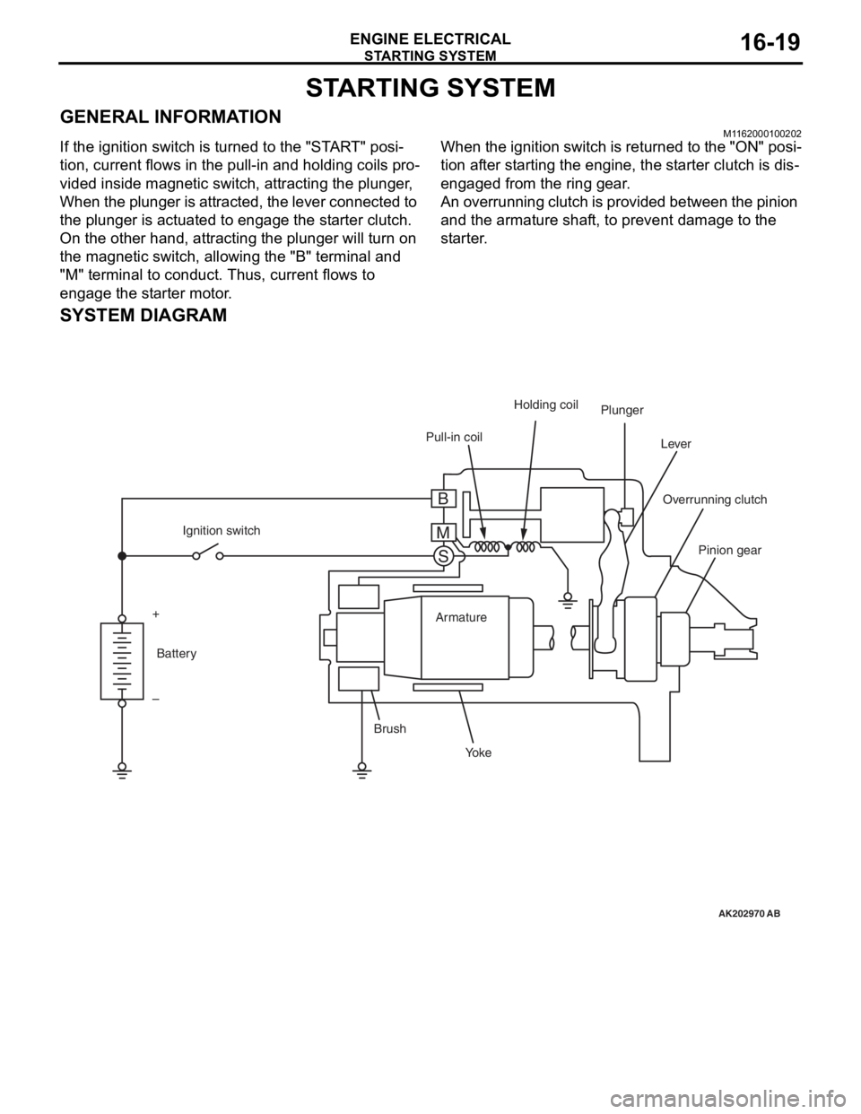
GENERAL INFORMATIONM1162000100202
If the ignition switch is turned to the "START" posi-
tion, current flows in the pull-in and holding coils pro-
vided inside magnetic switch, attracting the plunger,
When the plunger is attracted, the lever connected to
the plunger is actuated to engage the starter clutch.
On the other hand, attracting the plunger will turn on
the magnetic switch, allowing the "B" terminal and
"M" terminal to conduct. Thus, current flows to
engage the starter motor.
When the ignition switch is returned to the "ON" posi-
tion after starting the engine, the starter clutch is dis-
engaged from the ring gear.
An overrunning clutch is provided between the pinion
and the armature shaft, to prevent damage to the
starter.
SYSTEM DIAGRAM
AK202970
Pull-in coilHolding coil
Plunger
Lever
Pinion gear
Overrunning clutch
Yo k e
Brush Armature
Ignition switch
Battery
+
–
AB
B
M S
Page 85 of 800
STARTING SYSTEM
ENGINE ELECTRICAL16-23
STARTER MOTOR ASSEMBLY INSPECTION
M1162001100205
PINION GAP ADJUSTMENT
AK300648AB
<4G1>
Switch
S M
Wire Battery
Starter
motor
B
AKX01238
<4G6>
B
M S
battery Switch
Starter
motorWire
AG
1.
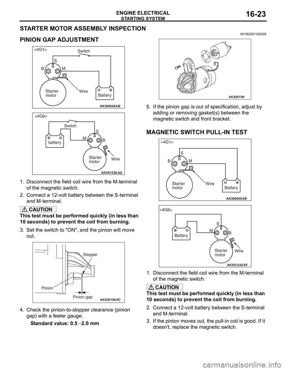
Disco nnect the field coil wire f r om th e M-te rmin al
of the magnet ic switch.
2.Conn ect a 12-volt b a ttery between the S-termina l
an d M-t e rminal.
CAUTION
This test must be performed quickly (in less than
10 seconds) to prevent the coil from burning.
3. Set the switch to "ON", and the pinion will move out.
AKX00198
Stopper
Pinion gap
Pinion
AC
4. Check the pinion-to-stopper clearance (pinion
gap) with a feeler gauge.
Standard value: 0.5 − 2.0 mm
AKX00199
5. If the pinion gap is out of specification, adjust by adding or removing gasket(s) between the
magnetic switch and front bracket.
MAGNETIC SWITCH PULL-IN TEST
AK300649AB
<4G1>
SM
Wire Battery
Starter
motor
B
AKX01242
<4G6>
SB
M
Battery
Starter
motorWire
AF
1. Disconnect the field coil wire from the M-terminal
of the magnetic switch.
CAUTION
This test must be performed quickly (in less than
10 seconds) to prevent the coil from burning.
2. Connect a 12-volt battery between the S-terminal and M-terminal.
3. If the pinion moves out, the pull-in coil is good. If it doesn't, replace the magnetic switch.
Page 86 of 800
STARTING SYSTEM
ENGINE ELECTRICAL16-24
MAGNETIC SWITCH HOLD-IN TEST
AK300650AB
<4G1>S
B MWire
Battery
Starter
motor
AKX01244
<4G6>
SB
M
Battery
Starter
motorWire
AF
1.
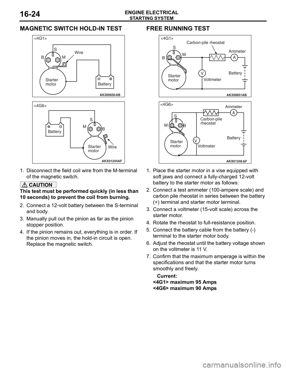
Disco nnect the field coil wire f r om th e M-te rmin al
of the magnet ic switch.
CAUTION
This test must be performed quickly (in less than
10 seconds) to prevent the coil from burning.
2. Connect a 12-volt battery between the S-terminal and body.
3. Manually pull out the pinion as far as the pinion stopper position.
4. If the pinion remains out, everything is in order. If
the pinion moves in, the hold-in circuit is open.
Replace the magnetic switch.
FREE RUNNING TEST
AK300651AB
<4G1>
S
A
M
V
B
Carbon-pile rheostat
Battery
Voltmeter Ammeter
Starter
motor
AKX01246
<4G6> S
M B Ammeter
Carbon-pile
rheostat
Battery
Starter
motor Voltmeter
AF
A
V
1. Place the starter motor in a vise equipped with soft jaws and connect a fully-charged 12-volt
battery to the starter motor as follows:
2. Connect a test ammeter (100-ampere scale) and carbon pile rheostat in series between the battery
(+) terminal and starter motor terminal.
3. Connect a voltmeter (15-volt scale) across the starter motor.
4. Rotate the rheostat to full-resistance position.
5. Connect the battery c able from the battery (-)
terminal to the starter motor body.
6. Adjust the rheostat until the battery voltage shown
on the voltmeter is 11 V.
7. Confirm that the maximum amperage is within the specifications and that the starter motor turns
smoothly and freely.
Current:
<4G1> maximum 95 Amps
<4G6> maximum 90 Amps
Page 87 of 800
STARTING SYSTEM
ENGINE ELECTRICAL16-25
MAGNETIC SWITCH RETURN TEST
AK300652AB
<4G1>S
B MWire
Battery
Starter
motor
AKX01248
<4G6>
SB
M
Battery
Starter
motorWire
AF
1.
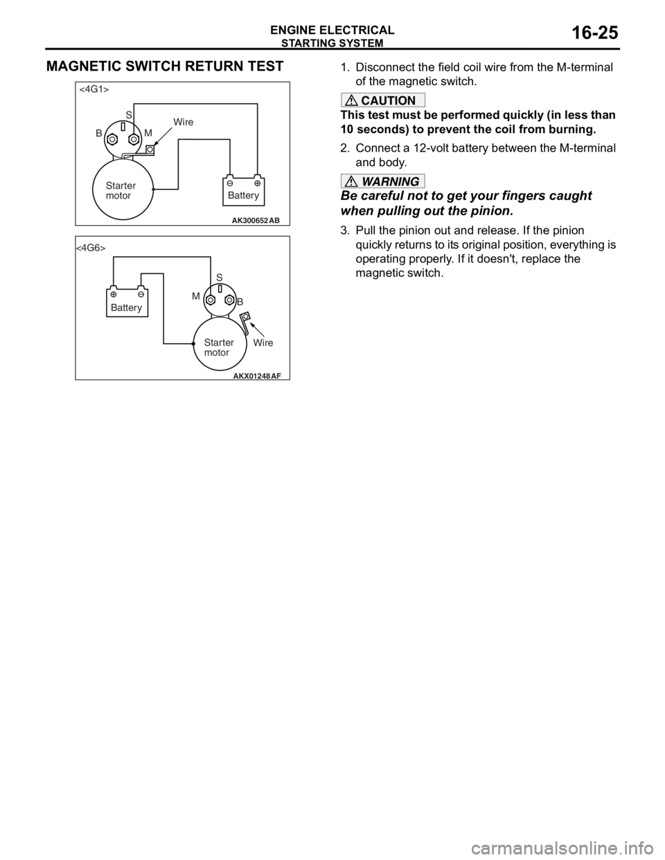
Disco nnect the field coil wire f r om th e M-te rmin al
o f the magnet ic switch.
CAUTION
This test must be performed quickly (in less than
10 seconds) to prevent the coil from burning.
2. Connect a 12-volt battery between the M-terminal and body.
WARNING
Be careful not to ge t your fingers caught
when pulling out the pinion.
3. Pull the pinion out and release. If the pinion
quickly returns to its original position, everything is
operating properly. If it doesn't, replace the
magnetic switch.
Page 90 of 800
AK202711
SegmentUndercut
Mica
AB
ST ARTING SYS TEM
ENGINE ELECTRICAL16-28
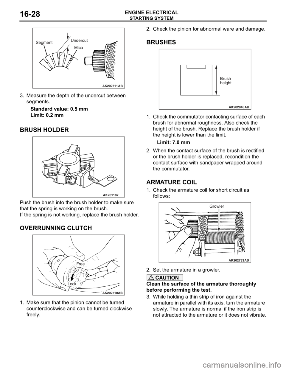
3.Measure the depth of the undercut be twe en
segment s.
St andard va lue: 0.5 mm
Limit: 0.2 mm
BRUSH HOLDER
AK201187
Push th e brush in to the b r ush hold e r to make sure
that the
spring is working o n the b r ush.
If the spring is not working, repla c e th e brush holder .
OVERRUNNING CLUTCH
AK202710
Free
Lock
AB
1.Make sure that th e pin i on canno t be tu rned
counte r clo ckwise a nd ca n be tu rned clockwise
fre e ly .
2.Check t he pinion for abn ormal ware an d damage.
BRUSHES
AK202846
Brush
height
AB
1.Che ck the commut ator con t a c tin g surface of each
b r ush f o r abno rmal rough ness. Also ch eck the
h e ight of the brush . Replace th e brush holder if
th e height is lo we r than t he limit.
Limit: 7.0 mm
2.Wh en the con t act su rface of the brush is rectified
o r the bru s h h o lder is re placed, re cond itio n the
cont act surfa c e wit h san d p a p e r wrapped around
th e co mmu t a t o r .
ARMATURE COIL
1.Check t he armature coil for short circuit a s
fo llows:
AK202733
Growler
AB
2.Set the armature in a growler .
CAUTION
Clean the surface of the armature thoroughly
before performing the test.
3. While holding a thin strip of iron against the
armature in parallel with it s axis, turn the armature
slowly. The armature is normal if the iron strip is
not attracted to the armature or it does not vibrate.
Page 91 of 800
AK202734
STARTING SYSTEM
ENGINE ELECTRICAL16-29
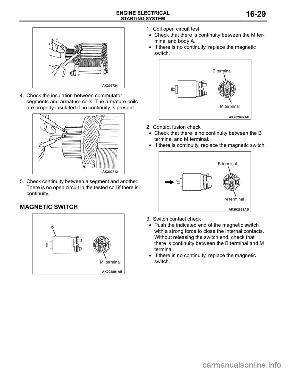
4. Check t he in sulation between commut ator
segment s an d arma ture coils. Th e armature coils
are prope rly insu lated if no con t inuity is pre s ent .
AK202713
5. Check continuit y bet ween a segment and another .
Th ere is n o ope n circui t in th e t e s t e d c o il if t h e r e is
continuity .
MA GNETIC SW ITCH
AK202891
A
M terminal
AB
1.Coil ope n circuit test
•Check that there is continuity be twe en the M te r-
minal and body A.
•
AK202892
M terminal
B terminal
AB
If th
ere is no continuit y , replace t he ma gnetic
sw
itc h .
2.Cont act fusion check
•Check that there is no co ntinu i ty between the B
termina
l and M te rmin al.
•
AK202893
M terminal
B terminal
AB
If th
ere is co ntinu i ty , re place the magn etic switch.
3.Switch cont act check
•Push the indicated end o f the magne tic switch
with
a stro ng force to close th e inte rnal cont act s .
Without re
leasing the switch end, check tha t
the
r e is con t inuity b e tween th e B terminal and M
termina
l .
•If there is no continuit y , replace t he ma gnetic
sw
itc h .
Page 92 of 800
IGNITION SYSTEM
ENGINE ELECTRICAL16-30
IGNITION SYSTEM
GENERAL INFORMATIONM1163000100294
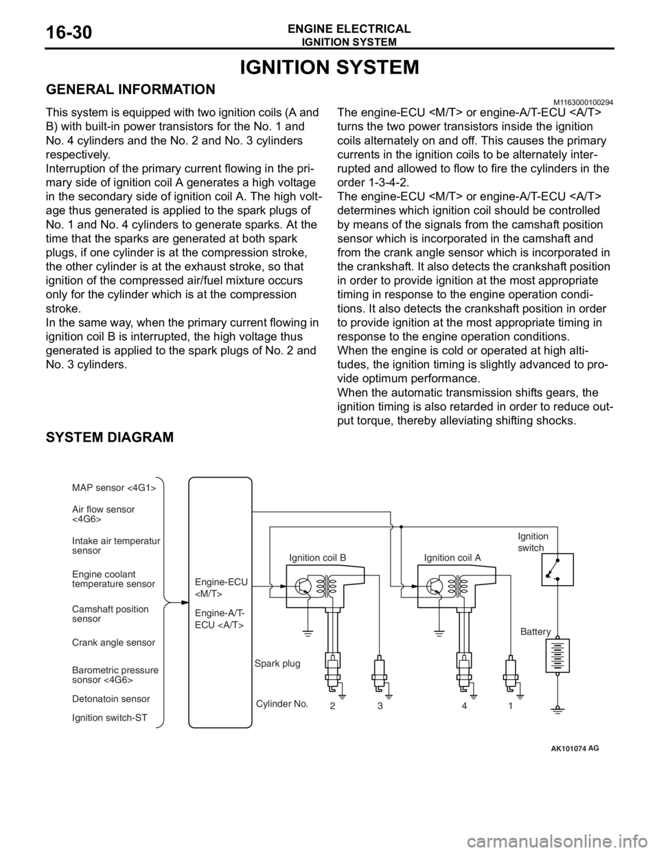
This system is equipped with two ignition coils (A and
B) with built-in power transistors for the No. 1 and
No. 4 cylinders and the No. 2 and No. 3 cylinders
respectively.
Interruption of the primary current flowing in the pri-
mary side of ignition coil A generates a high voltage
in the secondary side of ignition coil A. The high volt
-
age thus generated is applied to the spark plugs of
No. 1 and No. 4 cylinders to generate sparks. At the
time that the sparks are generated at both spark
plugs, if one cylinder is at the compression stroke,
the other cylinder is at the exhaust stroke, so that
ignition of the compressed air/fuel mixture occurs
only for the cylinder which is at the compression
stroke.
In the same way, when the primary current flowing in
ignition coil B is interrupted, the high voltage thus
generated is applied to the spark plugs of No. 2 and
No. 3 cylinders.
The engine-ECU
turns the two power transistors inside the ignition
coils alternately on and off. This causes the primary
currents in the ignition coils to be alternately inter
-
rupted and allowed to flow to fire the cylinders in the
order 1-3-4-2.
The engine-ECU
determines which ignition coil should be controlled
by means of the signals from the camshaft position
sensor which is incorporated in the camshaft and
from the crank angle sensor which is incorporated in
the crankshaft. It also detects the crankshaft position
in order to provide ignition at the most appropriate
timing in response to the engine operation condi
-
tions. It also detects the crankshaft position in order
to provide ignition at the most appropriate timing in
response to the engine operation conditions.
When the engine is cold or operated at high alti-
tudes, the ignition timing is slightly advanced to pro-
vide optimum performance.
When the automatic transmission shifts gears, the
ignition timing is also retarded in order to reduce out
-
put torque, thereby alleviating shifting shocks.
SYSTEM DIAGRAM
AK101074
Air flow sensor
<4G6> MAP sensor <4G1>
Intake air temperatur
sensor
Engine coolant
temperature sensor
Camshaft position
sensor
Crank angle sensor
Barometric pressure
sonsor <4G6>
Detonatoin sensor
Ignition switch-ST Engine-A/T-
ECU Engine-ECU
Ignition coil B
Cylinder No. 23 4
AG
1
Spark plug Ignition coil A
Ignition
switch
Battery
Page 93 of 800
IGNITION SYSTEM
ENGINE ELECTRICAL16-31
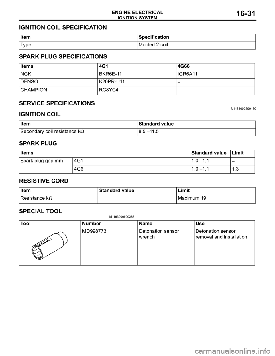
IGNITION COIL SPECIFICATION
ItemSpecification
Ty p eMolded 2-coil
SPARK PLUG SPECIFICATIONS
Items4G14G66
NGKBKR6E-11IGR6A11
DENSOK20PR-U11−
CHAMPIONRC8YC4−
SERVICE SPECIFICATIONSM1163000300180
IGNITION COIL
ItemStandard value
Secondary coil resistance kΩ8.5 − 11.5
SPARK PLUG
ItemsStandard valueLimit
Spark plug gap mm4G11.0 − 1.1−
4G61.0 − 1.11.3
RESISTIVE CORD
ItemStandard valueLimit
Resistance kΩ−Maximum 19
SPECIAL TOOL
M1163000600288
ToolNumberNameUse
MD998773Detonation sensor
wrenchDetonation sensor
removal and installation
Page 94 of 800
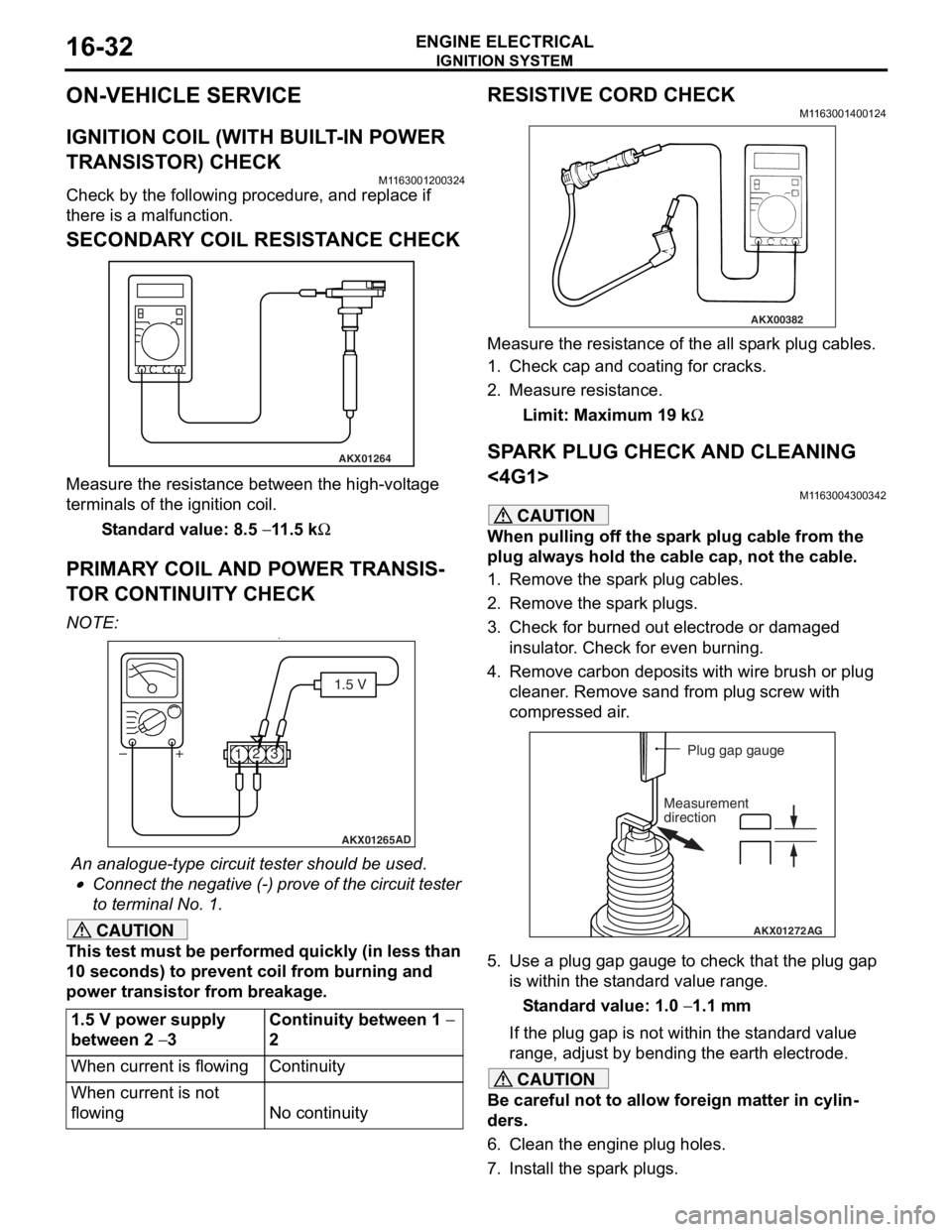
IGNITION SYSTEM
ENGINE ELECTRICAL16-32
ON-VEHICLE SERVICE
IGNITION COIL (WITH BUILT-IN POWER
TRANSISTOR) CHECK
M1163001200324
Check by the following procedure, and replace if
there is a malfunction.
SECONDARY COIL RESISTANCE CHECK
AKX01264
Measure the resist ance bet we en the high- volt ag e
terminals of th
e ign i tio n coil.
St andard va lue: 8.5 − 11 .5 kΩ
PRIM AR Y COIL AND POWER TRANSIS-
TO R CONTINUITY CHECK
NO TE: .•
AKX01265 AD
1.5 V
1 23
+
–
An analogue-t y pe circuit t e ster shou ld be use d .
•Connect the n egative (-) pro v e of the circuit t e ster
to t
e rminal No. 1.
CAUTION
This test must be performed quickly (in less than
10 seconds) to prevent coil from burning and
power transistor from breakage.
1.5 V power supply
between 2
− 3
Continuity between 1 −
2
When current is flowingContinuity
When current is not
flowing
No continuity
RESISTIVE CORD CHECK
M1163001400124
AKX00382
Measure the resistance of the all spark plug cables.
1. Check cap and coating for cracks.
2. Measure resistance.
Limit: Maximum 19 kΩ
SPARK PLUG CHECK AND CLEANING
<4G1>
M1163004300342
CAUTION
When pulling off the spark plug cable from the
plug always hold the cable cap, not the cable.
1. Remove the spark plug cables.
2. Remove the spark plugs.
3. Check for burned out electrode or damaged insulator. Check for even burning.
4. Remove carbon deposits with wire brush or plug cleaner. Remove sand from plug screw with
compressed air.
AKX01272 AG
Plug gap gauge
Measurement
direction
5. Use a plug gap gauge to check that the plug gap is within the standard value range.
Standard value: 1.0 − 1.1 mm
If the plug gap is not within the standard value
range, adjust by bending the earth electrode.
CAUTION
Be careful not to allow foreign matter in cylin-
ders.
6. Clean the engine plug holes.
7. Install the spark plugs.