window MITSUBISHI LANCER IX 2006 Owner's Guide
[x] Cancel search | Manufacturer: MITSUBISHI, Model Year: 2006, Model line: LANCER IX, Model: MITSUBISHI LANCER IX 2006Pages: 800, PDF Size: 45.03 MB
Page 353 of 800
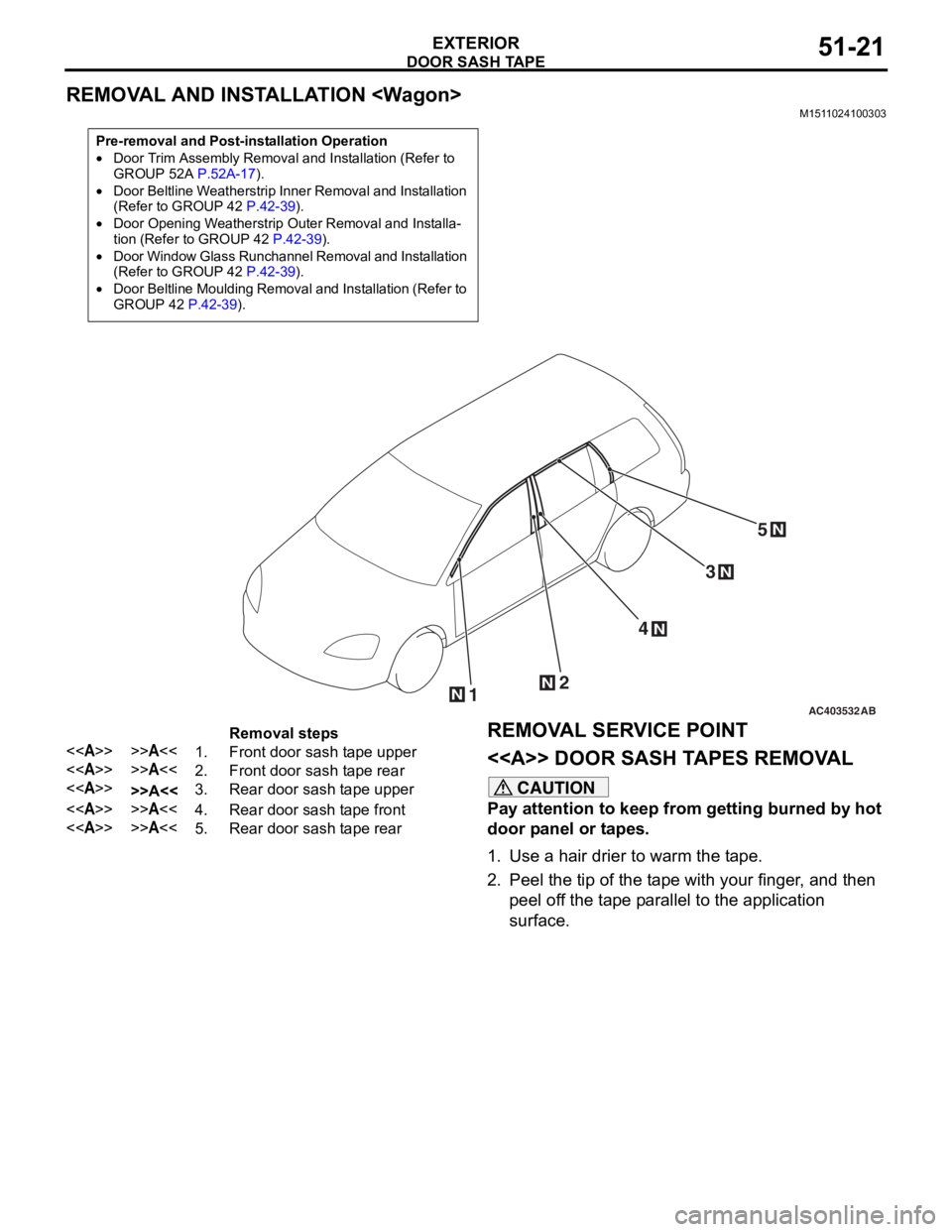
DOOR SASH TAPE
EXTERIOR51-21
REMOVAL AND INSTALLATION
M1511024100303
Pre-removal and Post-installation Operation
•Door Trim Assembly Removal and Installation (Refer to
GROUP 52A P.52A-17).
•Door Beltline Weatherstrip Inner Removal and Installation
(Refer to GROUP 42 P.42-39).
•Door Opening Weatherstrip Outer Removal and Installa-tion (Refer to GROUP 42 P.42-39).
•Door Window Glass Runchannel Removal and Installation
(Refer to GROUP 42 P.42-39).
•Door Beltline Moulding Removal and Installation (Refer to
GROUP 42 P.42-39).
AC40353212
4
3
N
N
N
N
5N
AB
Removal steps
<>>>A<<1.Front door sash tape upper
<>>>A<<2.Front door sash tape rear
<>>>A<<3.Rear door sash tape upper
<>>>A<<4.Rear door sash tape front
<>>>A<<5.Rear door sash tape rear
REMOVA L SER VICE POINT
<> DOOR SASH T A PES REMOV A L
CAUTION
Pay attention to keep from getting burned by hot
door panel or tapes.
1. Use a hair drier to warm the tape.
2. Peel the tip of the tape with your finger, and then
peel off the tape parallel to the application
surface.
Page 376 of 800
DOOR MIRROR
EXTERIOR51-44
SYMPTOM PROCEDURES
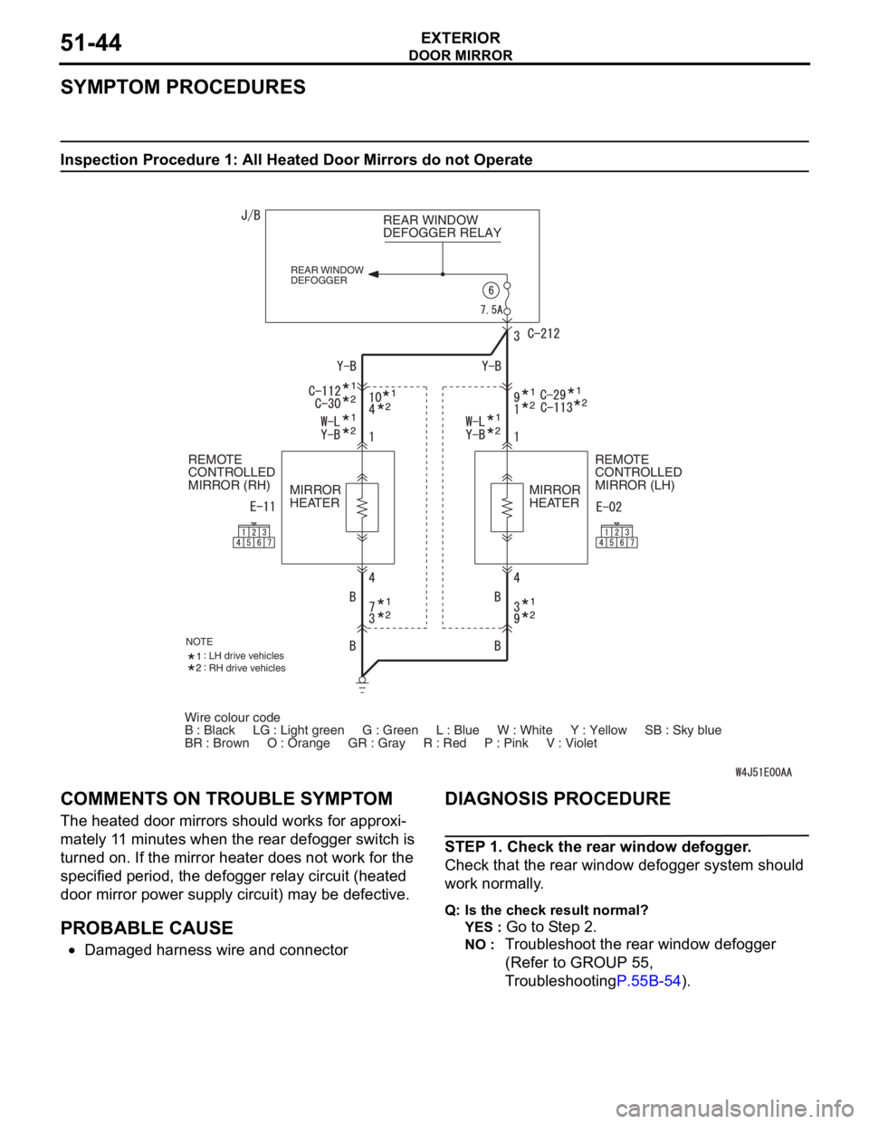
Inspection Procedure 1: All Heated Door Mirrors do not Operate
Wire colour code
B : Black LG : Light green G : Green L : Blue W : White \
Y : Yellow SB : Sky blue
BR : Brown O : Orange GR : Gray R : Red P : Pink V :\
Violet REAR WINDOW
DEFOGGER RELAY
REAR WINDOW
DEFOGGER
REMOTE
CONTROLLED
MIRROR (LH)
REMOTE
CONTROLLED
MIRROR (RH)
MIRROR
HEATER MIRROR
HEATER
NOTELH drive vehicles
RH drive vehicles
COMM
ENT S ON TROUBL E SYMPT O M
The heated do or mirrors shou ld works for approxi-
mately 11 minu tes whe n the re ar defo gger switch is
turned o
n . If th e mirror hea ter doe s no t work fo r the
specified period, th
e defo gger relay circuit (heated
door mirror p
o wer sup p ly circuit) may be d e fective .
PROBABLE CAUSE
•Damaged h a rness wire and connector
DIAGNOSIS PROCEDURE
STEP 1 . Check the rear wind ow de fogger .
Check that th e rear window def ogger system shou ld
wo
rk normally .
Q:Is t h e che c k r esu lt n o rmal?
YES : Go to S t ep 2 .
NO : Tr oublesh oot the rear win dow defog ger
(Refer to
GROUP 55 ,
T
r oublesh ootin g
P.55B-54).
Page 377 of 800
DOOR MIRROR
EXTERIOR51-45
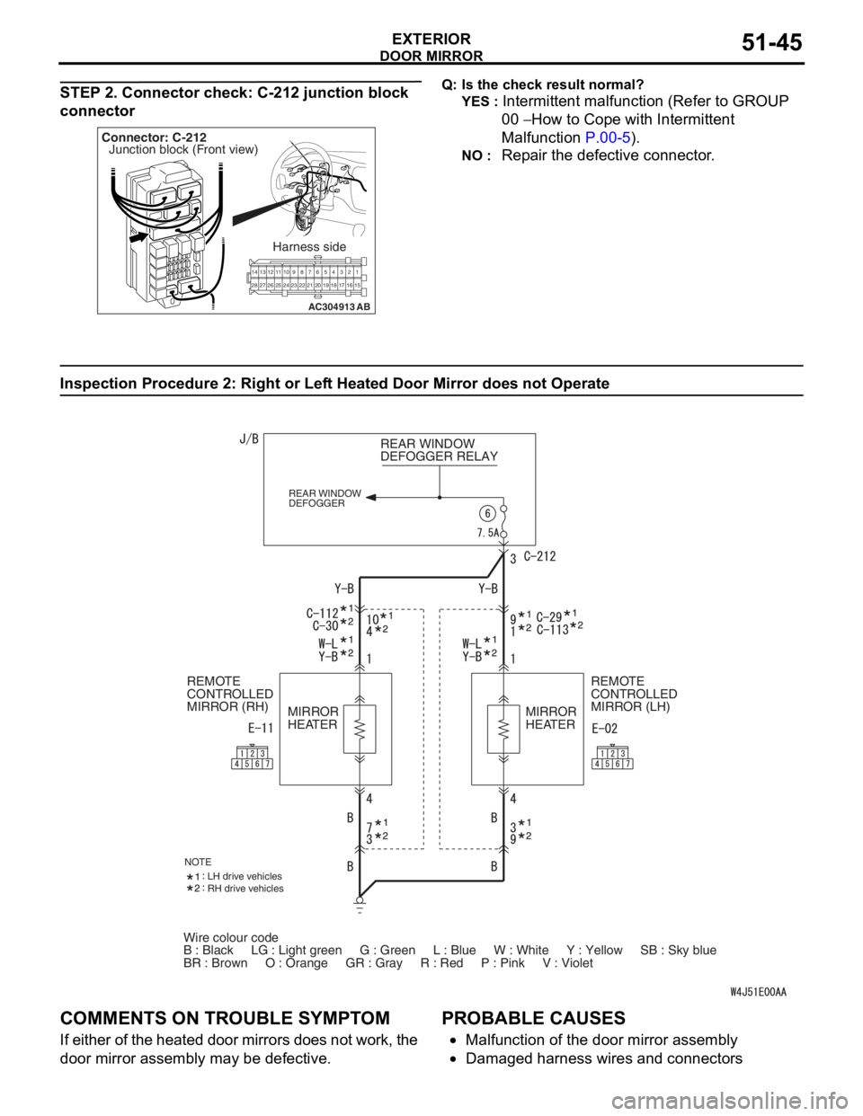
STEP 2. Connector check: C-212 junction block
connector
AC304913
21716151718
201912345
623 222425282627981011141213
Connector: C-212
Harness side
AB
Junction block (Front view)
Q: Is t h e che c k r esu lt n o rmal?
YES : Intermittent malfun ctio n (Refer to GROUP
00
− Ho w to Cope wit h Intermitte nt
Ma
lfunction
P.00-5).
NO : Repa ir th e defective connector .
Inspection Procedure 2 : Ri ght or Lef t Hea t ed Door Mirror does not Operate
Wire colour code
B : Black LG : Light green G : Green L : Blue W : White \
Y : Yellow SB : Sky blue
BR : Brown O : Orange GR : Gray R : Red P : Pink V :\
Violet REAR WINDOW
DEFOGGER RELAY
REAR WINDOW
DEFOGGER
REMOTE
CONTROLLED
MIRROR (LH)
REMOTE
CONTROLLED
MIRROR (RH)
MIRROR
HEATER MIRROR
HEATER
NOTELH drive vehicles
RH drive vehicles
COMM
ENT S ON TROUBL E SYMPT O M
If eit her of t he hea ted d oor mirrors does n o t work, the
door mirror a
sse mbly may b e defe c tive.
PROBABLE CAUSES
•Malfunctio n of th e door mirro r assemb ly
•Damaged ha rness wires and con necto rs
Page 379 of 800
DOOR MIRROR
EXTERIOR51-47
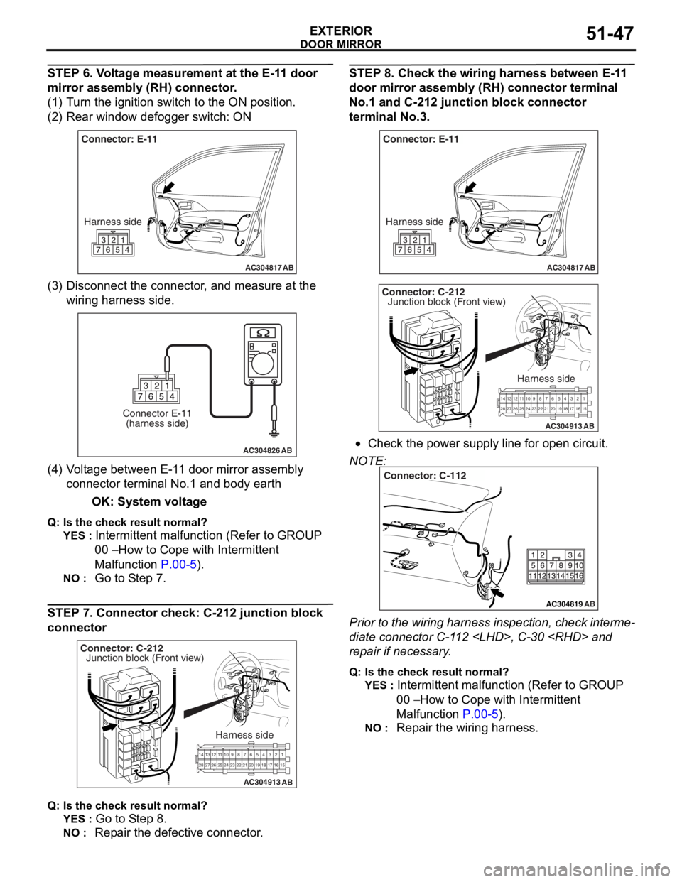
STEP 6. Voltage measurement at the E-11 door
mirror assembly (RH) connector.
(1) Turn the ignition switch to the ON position.
(2) Rear window defogger switch: ON
AC304817
Connector: E-11Harness side
AB
(3) D isconn ect t he co nnector , an d me asure at the
wiring harn e ss side.
AC304826
Connector E-11(harness side)
AB
(4) V olt a g e between E-1 1 door mirror assembly
co nnector termina l No.1 a nd bod y ea rth
OK: System vo lt age
Q: Is the check result normal?
YES : Intermittent ma lfun ctio n (Refer to GROUP
00
− Ho w t o Cope wit h Intermitte nt
Malfunction
P.00-5).
NO : Go to S t ep 7.
STEP 7. Co nnector ch eck: C-212 junction block
connecto
r
AC304913
21716151718
201912345
623 222425282627981011141213
Connector: C-212
Harness side
AB
Junction block (Front view)
Q : Is the check result normal?
YES : Go to S t ep 8.
NO : Repa ir the defective connector .
STEP 8 . Check the wiring harness b e twee n E-1 1
door mirror assem
bly (RH) conne ctor terminal
No.
1 and C-21 2 junctio n block connec tor
terminal No.3
.
AC304817
Connector: E-11
Harness side
AB
AC304913
21716151718
201912345
623 222425282627981011141213
Connector: C-212
Harness side
AB
Junction block (Front view)
•Check th e power supply line fo r open circuit.
NOTE:
AC304819
Connector: C-112
AB
Prior to the wiring harness insp ection, check interme-
diate connector C-1 1 2
rep
a ir if necessary .
Q:Is t h e che c k r esu lt n o rmal?
YES : Intermittent malfun ctio n (Refer to GROUP
00
− Ho w to Cope wit h Intermitte nt
Ma
lfunction
P.00-5).
NO : Repa ir th e wirin g harne ss.
Page 392 of 800

ECU
COMPONENT LOCATIONS70-2
ECU
M1701000500311
NameSymbolNameSymbol
A/C-ECUEFront-ECUB
ABS-ECUAHeater control unit
Column switch (incorporating
Column-ECU)DImmobilizer-ECUG
Engine-A/T-ECU IPower window main switch
(incorporating ECU)K
Engine-ECU
(incorporating ECU)J
ETACS-ECUFSRS-ECUH
Cooling fan motor drive control unitC
AC301182
DE
AB
C
FGHI
AB
DE
AB
C
FGHI
Page 394 of 800
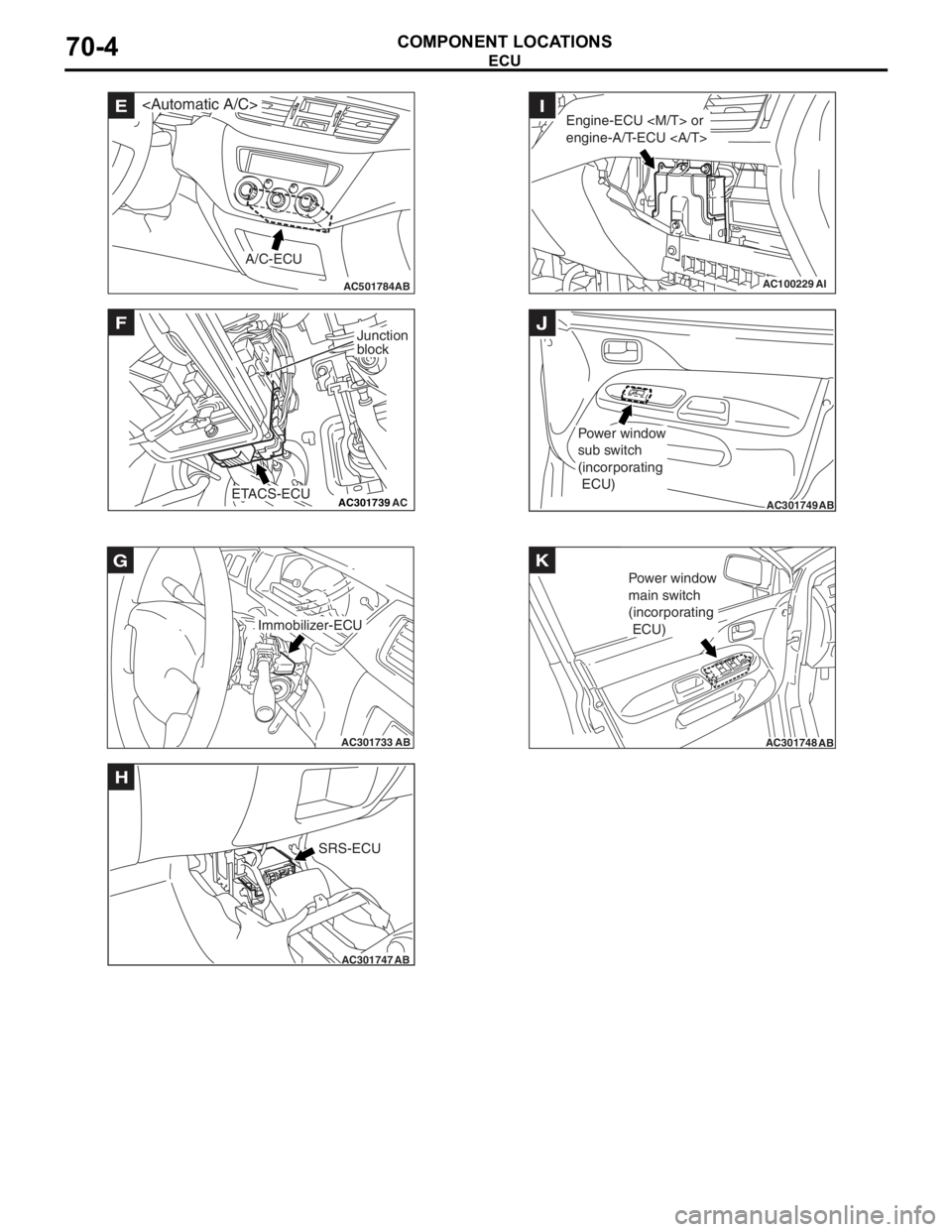
AC501784AB
E
A/C-ECU
AC301739AC
F
ETACS-ECU
Junction
block
AC301733AB
Immobilizer-ECU
G
AC301747AB
SRS-ECU
H
AC100229AI
Engine-ECU
engine-A/T-ECU I
AC301749AB
Power window
sub switch
(incorporating
ECU)
J
AC301748AB
Power window
main switch
(incorporating
ECU)
K
ECU
COMPONENT LOCA
TIONS70-4
Page 395 of 800
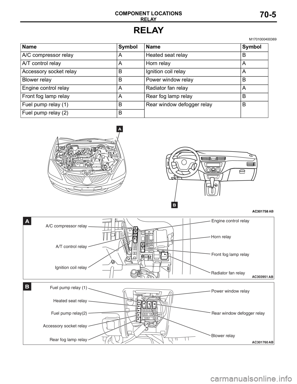
RELAY
COMPONENT LOCATIONS70-5
RELAY
M1701000400369
NameSymbolNameSymbol
A/C compressor relayAHeated seat relayB
A/T control relayAHorn relayA
Accessory socket relayBIgnition coil relayA
Blower relayBPower window relayB
Engine control relayARadiator fan relayA
Front fog lamp relayARear fog lamp relayB
Fuel pump relay (1)BRear window defogger relayB
Fuel pump relay (2)B
AC301758AB
A
B
AC303951AB
A/C compressor relayEngine control relay
Horn relay
Front fog lamp relay
Radiator fan relay
A/T control relay
Ignition coil relayA
AC301760
Fuel pump relay (1) Power window relay
Rear window defogger relay
Blower relay
Heated seat relay
Fuel pump relay(2)
Accessory socket relay
Rear fog lamp relayAB
B
Page 441 of 800
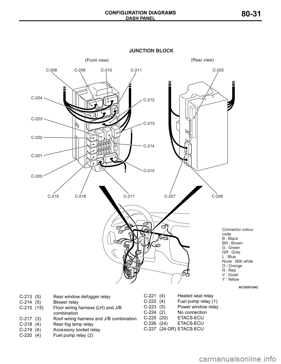
AC302010AC
(Front view)(Rear view)
C-208 C-209 C-210 C-211
C-212
C-213
C-214
C-215
C-217
C-218
C-219
C-220 C-221 C-222 C-223 C-224 C-225
C-226
C-227
JUNCTION BLOCK
Connector colour
code
B : Black
BR : Brown
G : Green
GR : Grey
L : Blue
None : Milk white
O : Orange
R : Red
V : Violet
Y : Yellow
C-213(5)Rear window defogger relay
C-214(5)Blower relay
C-215(15)Floor wiring harness (LH) and J/B
combination
C-217(3)Roof wiring harness and J/B combination
C-218(4)Rear fog lamp relay
C-219(4)Accessory socket relay
C-220(4)Fuel pump relay (2)
C-221(4)Heated seat relay
C-222(4)Fuel pump relay (1)
C-223(5)Power window relay
C-224(2)No connection
C-225(20)ETACS-ECU
C-226(24)ETACS-ECU
C-227(24-GR)ETACS-ECU
DASH P ANEL
CONF IGURA TION D I A G RA MS80-31
Page 447 of 800
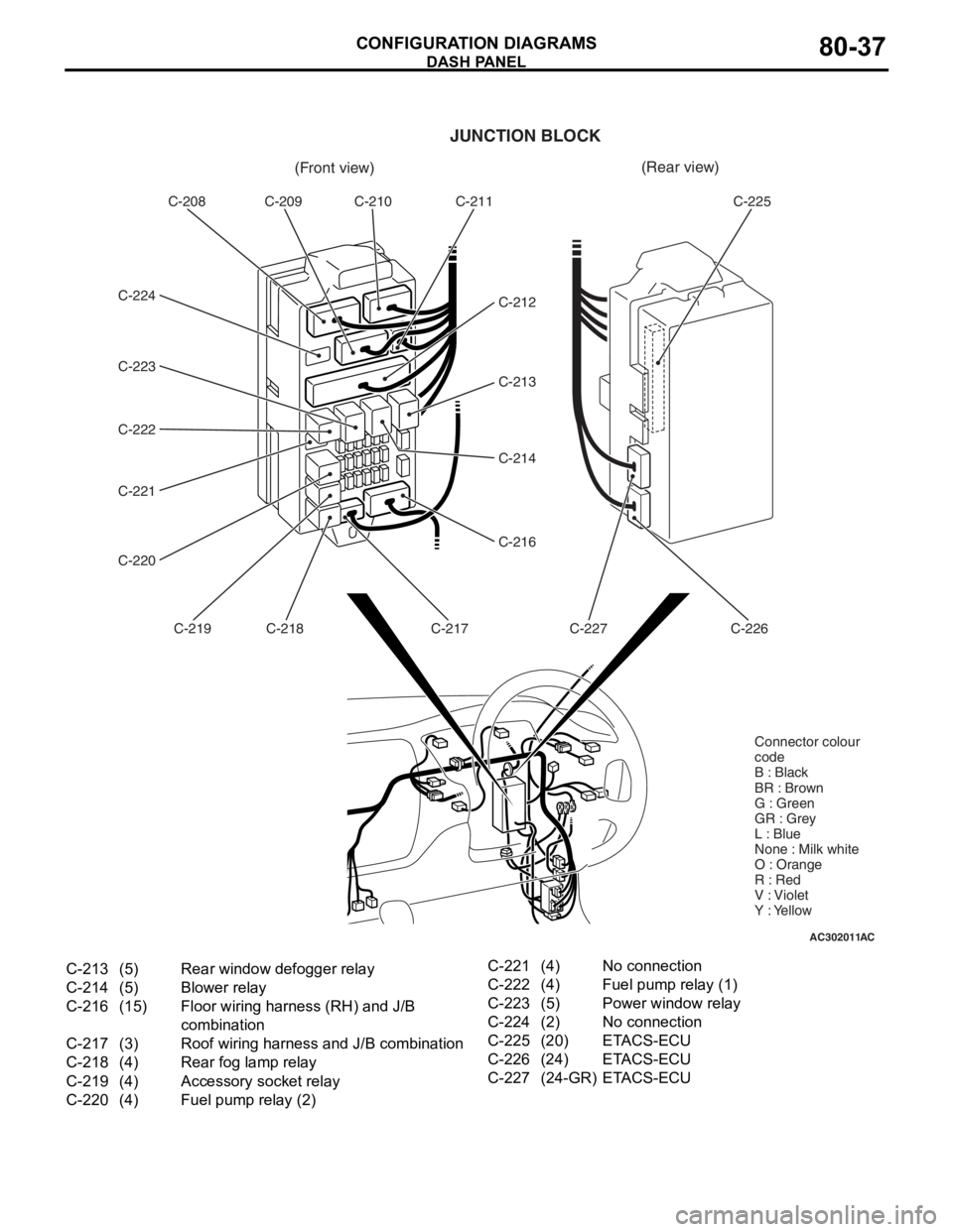
AC302011AC
(Front view)(Rear view)
C-208 C-209 C-210 C-211
C-212
C-213
C-214
C-216
C-217
C-218
C-219
C-220 C-221 C-222 C-223 C-224 C-225
C-226
C-227
JUNCTION BLOCK
Connector colour
code
B : Black
BR : Brown
G : Green
GR : Grey
L : Blue
None : Milk white
O : Orange
R : Red
V : Violet
Y : Yellow
C-213(5)Rear window defogger relay
C-214(5)Blower relay
C-216(15)Floor wiring harness (RH) and J/B
combination
C-217(3)Roof wiring harness and J/B combination
C-218(4)Rear fog lamp relay
C-219(4)Accessory socket relay
C-220(4)Fuel pump relay (2)
C-221(4)No connection
C-222(4)Fuel pump relay (1)
C-223(5)Power window relay
C-224(2)No connection
C-225(20)ETACS-ECU
C-226(24)ETACS-ECU
C-227(24-GR)ETACS-ECU
DASH P ANEL
CONF IGURA TION D I A G RA MS80-37
Page 456 of 800
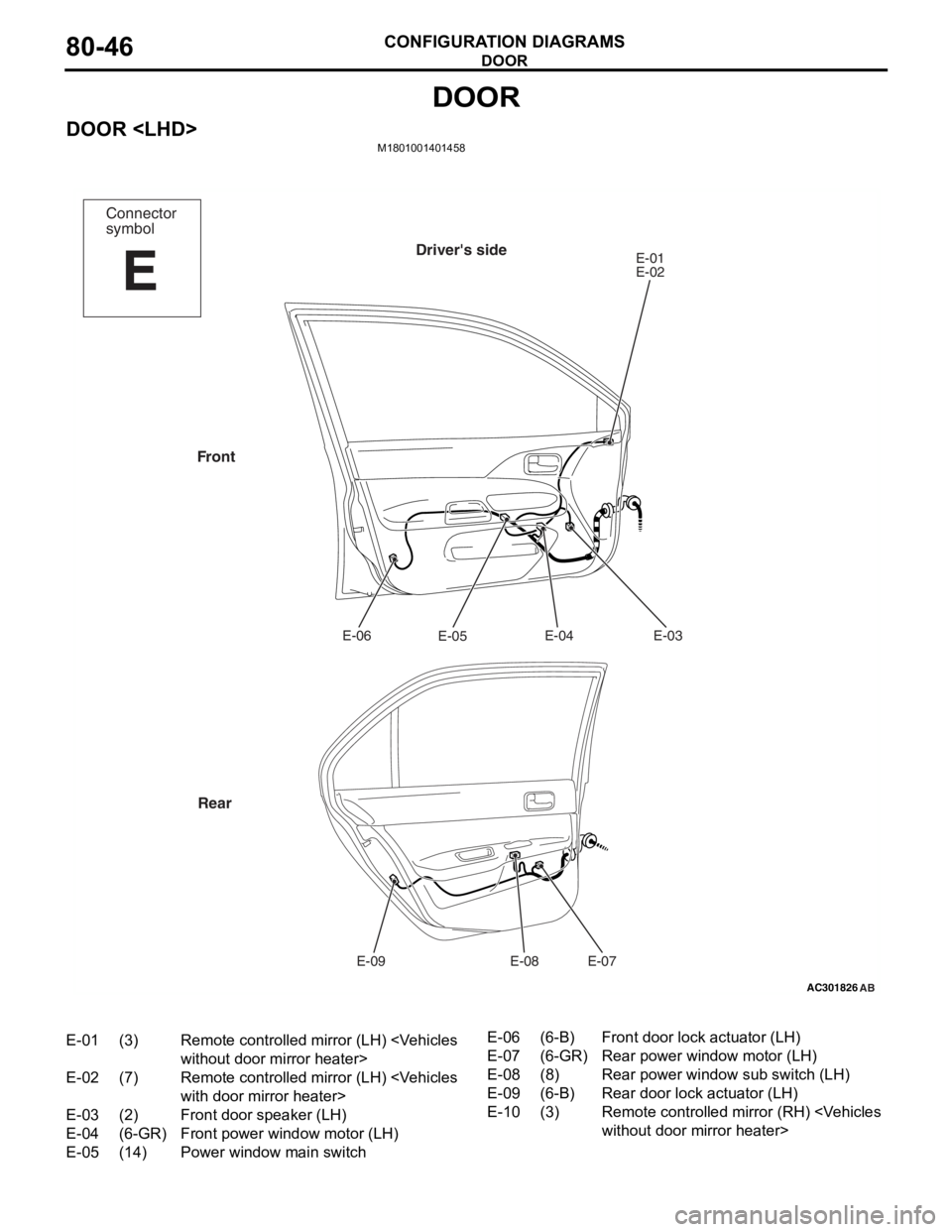
DOOR
CONFIGURATION DIAGRAMS80-46
DOOR
DOOR
AC301826
Connector
symbol
E
Driver's sideE-01
E-02E-03
E-04
E-05
E-06
E-07
E-08
E-09
Front
Rear
AB
E-01(3)Remote controlled mirror (LH)
E-02(7)Remote controlled mirror (LH)
E-03(2)Front door speaker (LH)
E-04(6-GR)Front power window motor (LH)
E-05(14)Power window main switch
E-06(6-B)Front door lock actuator (LH)
E-07(6-GR)Rear power window motor (LH)
E-08(8)Rear power window sub switch (LH)
E-09(6-B)Rear door lock actuator (LH)
E-10(3)Remote controlled mirr or (RH)