Timing MITSUBISHI LANCER IX 2006 Service Manual
[x] Cancel search | Manufacturer: MITSUBISHI, Model Year: 2006, Model line: LANCER IX, Model: MITSUBISHI LANCER IX 2006Pages: 800, PDF Size: 45.03 MB
Page 8 of 800
GENERAL INFORMATION
ENGINE LUBRICATION12-2
GENERAL INFORMATION
M1121000100357
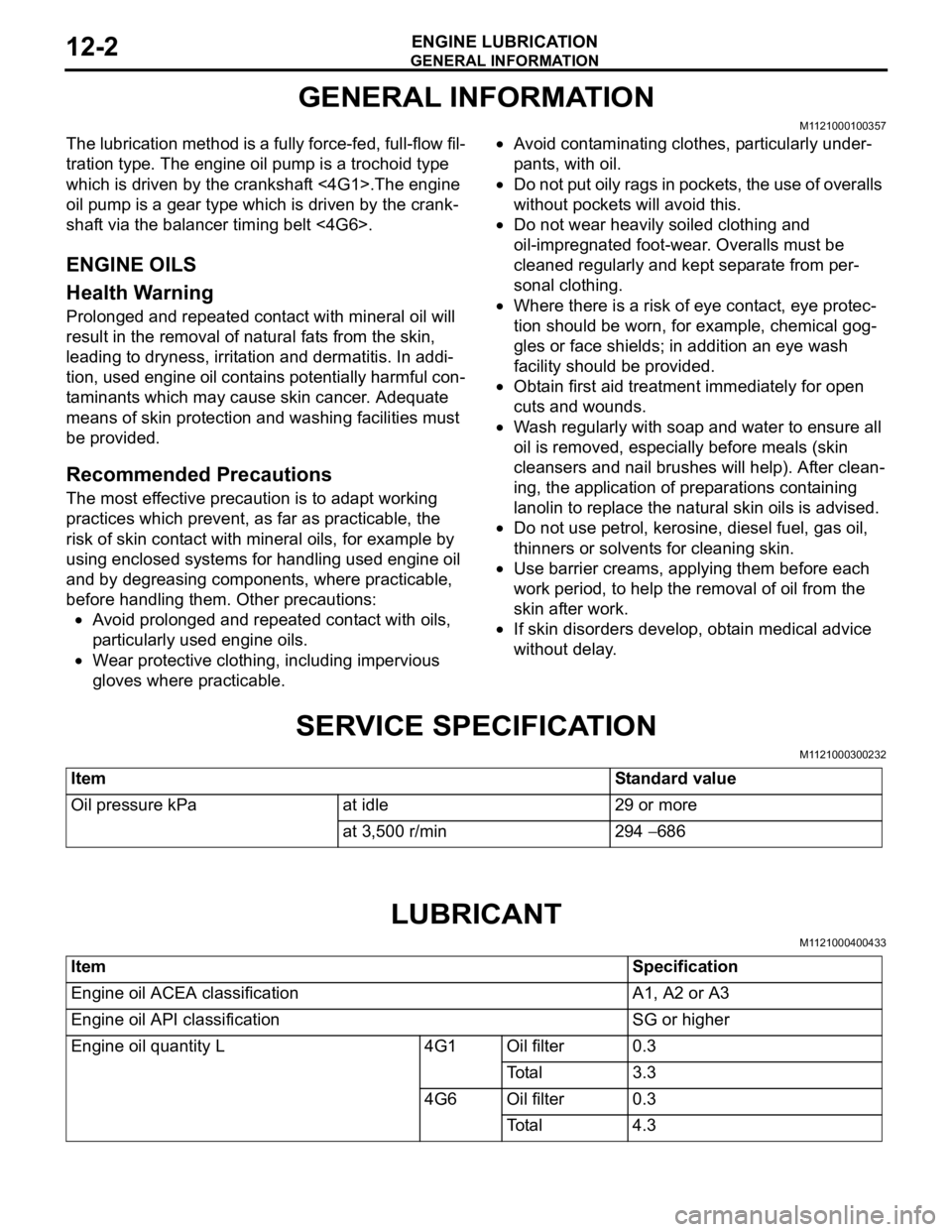
The lubrication method is a fully force-fed, full-flow fil-
tration type. The engine oil pump is a trochoid type
which is driven by the crankshaft <4G1>.The engine
oil pump is a gear type which is driven by the crank
-
shaft via the balancer timing belt <4G6>.
ENGINE OILS
Health Warning
Prolonged and repeated contact with mineral oil will
result in the removal of natural fats from the skin,
leading to dryness, irritation and dermatitis. In addi
-
tion, used engine oil contains potentially harmful con-
taminants which may cause skin cancer. Adequate
means of skin protection and washing facilities must
be provided.
Recommended Precautions
The most effective precaution is to adapt working
practices which prevent, as far as practicable, the
risk of skin contact with mineral oils, for example by
using enclosed systems for handling used engine oil
and by degreasing components, where practicable,
before handling them. Other precautions:
•Avoid prolonged and repeated contact with oils,
particularly used engine oils.
•Wear protective clothing, including impervious
gloves where practicable.
•Avoid contaminating clothes, particularly under-
pants, with oil.
•Do not put oily rags in pockets, the use of overalls
without pockets will avoid this.
•Do not wear heavily soiled clothing and
oil-impregnated foot-wear. Overalls must be
cleaned regularly and kept separate from per
-
sonal clothing.
•Where there is a risk of eye contact, eye protec-
tion should be worn, for example, chemical gog-
gles or face shields; in addition an eye wash
facility should be provided.
•Obtain first aid treatment immediately for open
cuts and wounds.
•Wash regularly with soap and water to ensure all
oil is removed, especially before meals (skin
cleansers and nail brushes will help). After clean
-
ing, the application of preparations containing
lanolin to replace the natur al skin oils is advised.
•Do not use petrol, kerosine, diesel fuel, gas oil,
thinners or solvents for cleaning skin.
•Use barrier creams, applying them before each
work period, to help the removal of oil from the
skin after work.
•If skin disorders develop, obtain medical advice
without delay.
SERVICE SPECIFICATION
M1121000300232
ItemStandard value
Oil pressure kPaat idle29 or more
at 3,500 r/min294 − 686
LUBRICANT
M1121000400433
ItemSpecification
Engine oil ACEA classificationA1, A2 or A3
Engine oil API classificationSG or higher
Engine oil quantity L4G1Oil filter0.3
To t a l3.3
4G6Oil filter0.3
To t a l4.3
Page 41 of 800
WATE R P U M P
ENGINE COOLING14-27
WAT E R P U M P
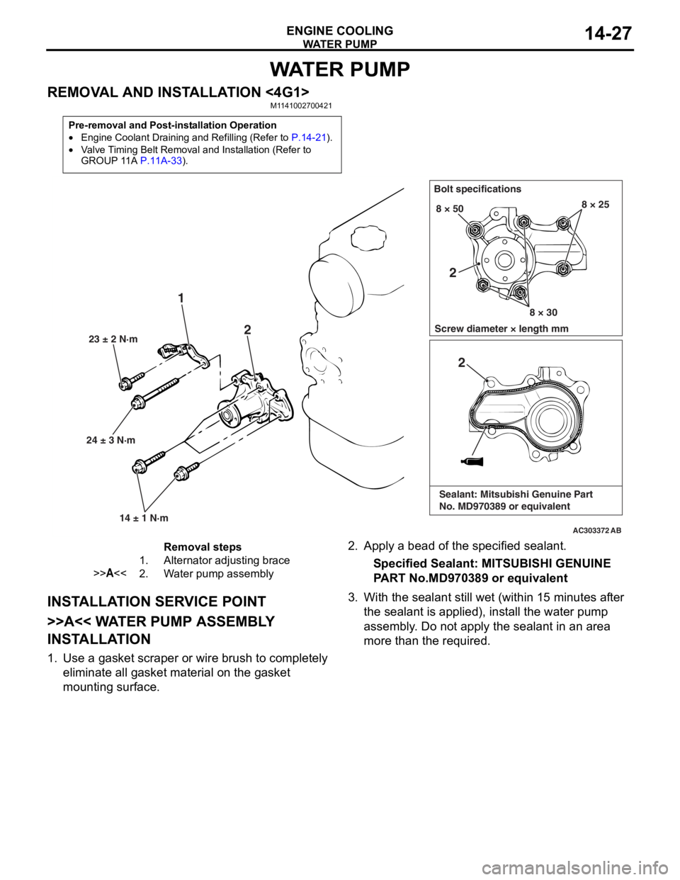
REMOVAL AND INSTALLATION <4G1>M1141002700421
Pre-removal and Post-installation Operation
•Engine Coolant Draining and Refilling (Refer to P.14-21).
•Valve Timing Belt Removal and Installation (Refer to
GROUP 11A P.11A-33).
AC303372
24 ± 3 N·m23 ± 2 N·m
14 ± 1 N·m
1 2
Bolt specifications
Screw diameter × length mm 8 × 50
8 × 308 × 25
AB
2
2
Sealant: Mitsubishi Genuine Part
No. MD970389 or equivalent
Removal steps
1.Alternator adjusting brace
>>A<<2.Water pump assembly
INST ALLA T ION SER VICE POINT
>>A<< WA TER PUMP ASSEMBL Y
INST
ALLA TION
1.Use a gaske t scraper o r wire brush to complet e ly
eliminate all gasket material o n the g a sket
mounting surface.
2. App l y a bead of the specified sealan t.
Specified Sealant: MITSUBISHI GENUINE
P
ART No.MD970 389 or eq uivalen t
3.With the sea l ant still wet (within 1 5 minutes af ter
th e se alant is applied), inst all the wa ter pump
a sse mbly . Do not a pply the sealant in an are a
more th an the required.
Page 42 of 800
WATE R P U M P
ENGINE COOLING14-28
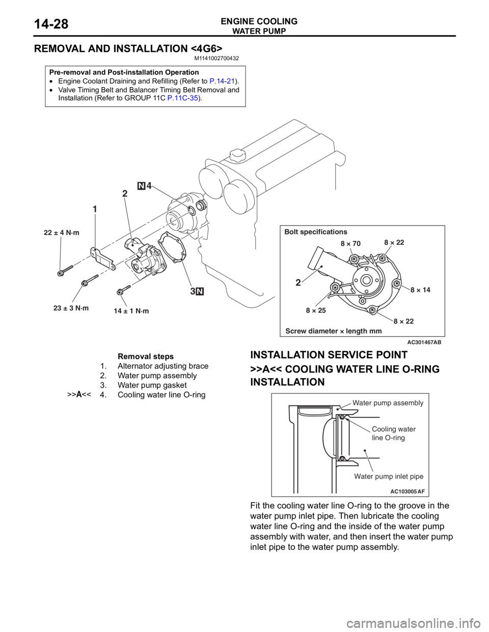
REMOVAL AND INSTALLATION <4G6>
M1141002700432
Pre-removal and Post-installation Operation
•Engine Coolant Draining and Refilling (Refer to P.14-21).
•Valve Timing Belt and Balancer Timing Belt Removal and
Installation (Refer to GROUP 11C
P.11C-35).
AC301467
22 ± 4 N·m23 ± 3 N·m 14 ± 1 N·m
12
3
4
N
N
Bolt specifications
Screw diameter × length mm
8 × 70 8 × 22
8 × 14
8 × 22
8 × 25
2
AB
Removal steps
1.Alternator adjusting brace
2.Water pump assembly
3.Water pump gasket
>>A<<4.Cooling water line O-ring
INST
ALLA T ION SER VICE POINT
>>A<< COOLING WA TER LINE O-RING
INST
ALLA TION
AC103005
Water pump assembly
Cooling water
line O-ring
Water pump inlet pipe
AF
Fit the coo ling water line O-ring to the groove in the
wa
ter pump in let p i pe. T hen lubricate th e co olin g
wa
ter line O-ring and the inside of the wat e r pump
assembly with wa
ter , and then insert the wa ter pu mp
inle
t pip e to the water pu mp asse mbly .
Page 92 of 800
IGNITION SYSTEM
ENGINE ELECTRICAL16-30
IGNITION SYSTEM
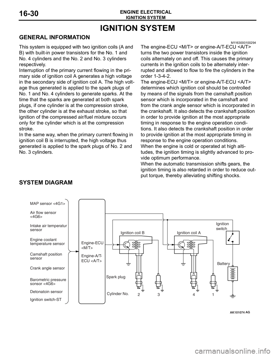
GENERAL INFORMATIONM1163000100294
This system is equipped with two ignition coils (A and
B) with built-in power transistors for the No. 1 and
No. 4 cylinders and the No. 2 and No. 3 cylinders
respectively.
Interruption of the primary current flowing in the pri-
mary side of ignition coil A generates a high voltage
in the secondary side of ignition coil A. The high volt
-
age thus generated is applied to the spark plugs of
No. 1 and No. 4 cylinders to generate sparks. At the
time that the sparks are generated at both spark
plugs, if one cylinder is at the compression stroke,
the other cylinder is at the exhaust stroke, so that
ignition of the compressed air/fuel mixture occurs
only for the cylinder which is at the compression
stroke.
In the same way, when the primary current flowing in
ignition coil B is interrupted, the high voltage thus
generated is applied to the spark plugs of No. 2 and
No. 3 cylinders.
The engine-ECU
turns the two power transistors inside the ignition
coils alternately on and off. This causes the primary
currents in the ignition coils to be alternately inter
-
rupted and allowed to flow to fire the cylinders in the
order 1-3-4-2.
The engine-ECU
determines which ignition coil should be controlled
by means of the signals from the camshaft position
sensor which is incorporated in the camshaft and
from the crank angle sensor which is incorporated in
the crankshaft. It also detects the crankshaft position
in order to provide ignition at the most appropriate
timing in response to the engine operation condi
-
tions. It also detects the crankshaft position in order
to provide ignition at the most appropriate timing in
response to the engine operation conditions.
When the engine is cold or operated at high alti-
tudes, the ignition timing is slightly advanced to pro-
vide optimum performance.
When the automatic transmission shifts gears, the
ignition timing is also retarded in order to reduce out
-
put torque, thereby alleviating shifting shocks.
SYSTEM DIAGRAM
AK101074
Air flow sensor
<4G6> MAP sensor <4G1>
Intake air temperatur
sensor
Engine coolant
temperature sensor
Camshaft position
sensor
Crank angle sensor
Barometric pressure
sonsor <4G6>
Detonatoin sensor
Ignition switch-ST Engine-A/T-
ECU Engine-ECU
Ignition coil B
Cylinder No. 23 4
AG
1
Spark plug Ignition coil A
Ignition
switch
Battery
Page 97 of 800
IGNITION SYSTEM
ENGINE ELECTRICAL16-35
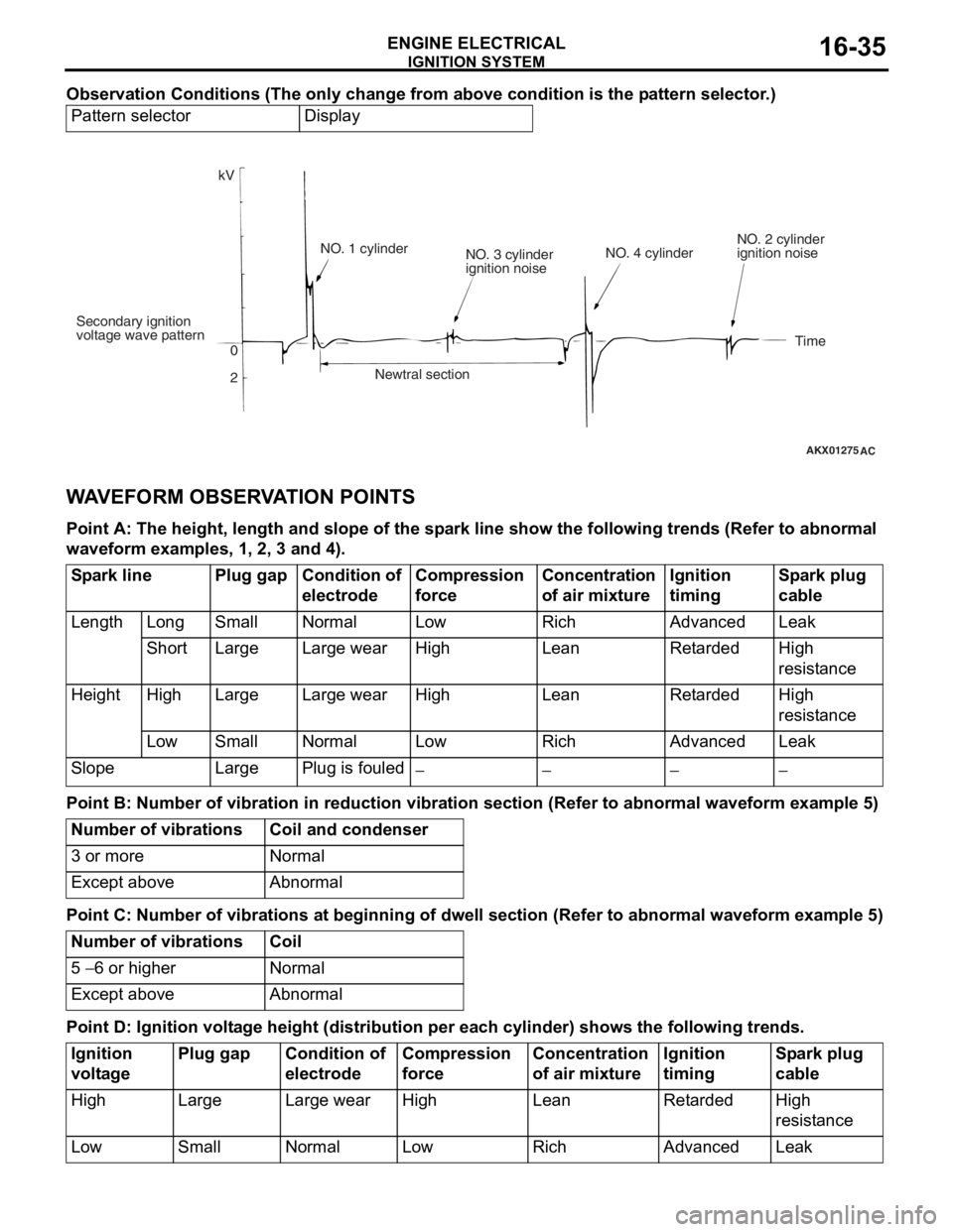
Observation Conditions (The only change from above condition is the pattern selector.)
Pattern selectorDisplay
AKX01275
kV
Secondary ignition
voltage wave pattern 0
2NO. 1 cylinder
NO. 3 cylinder
ignition noise
Newtral section NO. 4 cylinder
NO. 2 cylinder
ignition noise
Time
AC
WA VEFORM OBSER V A T ION POINTS
Point A: The he ight, len g th and s l ope of th e sp a r k line sho w the following trends (Re f er to abnorma l
wave
form exam ples, 1 , 2, 3 a nd 4).
Spark linePlug gapCondition of
electrodeCompression
force Concentration
of air mixtureIgnition
timingSpark plug
cable
LengthLongSmallNormalLowRichAdvancedLeak
ShortLargeLarge wearHigh LeanRetardedHigh
resistance
HeightHighLargeLarge wearHighLeanRetardedHigh
resistance
LowSmallNormalLow RichAdvancedLeak
SlopeLargePlug is fouled−−−−
Point B: Number of v i bra t ion in red uction vi bra t ion sec tion (Refer to a bnormal wavefo r m examp l e 5)
Number of vibrationsCoil and condenser
3 or moreNormal
Except aboveAbnormal
Point C: Number of v i bra t ions a t beginnin g of dwell se ction (Refer to a bnormal wave form exam ple 5)
Number of vibrationsCoil
5 − 6 or higherNormal
Except aboveAbnormal
Point D: Ignition volt a g e height (distribution per each cylinder) s hows the follo wing tren ds.
Ignition
voltagePlug gapCondition of
electrodeCompression
forceConcentration
of air mixtureIgnition
timingSpark plug
cable
HighLargeLarge wearHighLeanRetardedHigh
resistance
LowSmallNormalLowRichAdvancedLeak
Page 103 of 800

IGNITION SYSTEM
ENGINE ELECTRICAL16-41
CRANKSHAFT POSITION SENSOR
REMOVAL AND INSTALLATION <4G1>
M1163003500439
Pre-removal and Post-installation Operation
•Valve Timing Belt Removal and Installation (Refer to
GROUP 11A P.11A-33).
AC208380AB
12
11 ± 1 N·m
8.8 ± 1.0 N·m
Removal steps
1.Engine crank angle sensor
2.Crank angle sensor connector
bracket
Page 104 of 800

IGNITION SYSTEM
ENGINE ELECTRICAL16-42
REMOVAL AND INSTALLATION <4G6>
M1163003500440
Pre-removal and Post-installation Operation
•Valve Timing Belt Removal and Installation (Refer to
GROUP 11C P.11C-35).
AC301612
8.8 ± 1.0 N·m
8
8.8 ± 1.0 N·m
9
1
22 ± 4 N·m
4
2
3
49 ± 9 N·m49 ± 9 N·m5
22 ± 4 N·m
3.0 ± 0.5 N·m
6
7
AC
Removal steps
1.Power steering pressure switch
connector
2.A/C compressor connector
3.A/C compressor connector clamp
<>4.Power steering oil pump assembly
5.Power steering oil pump bracket
6.Rocker cover centre cover
7.Engine crank angle sensor
connector
8.Engine crank angle sensor
9.Crank angle sensor connector
bracket
REMOV A L SER VICE POINT
<> POWE R STEERING OIL PUMP
ASSEMBL
Y REMOV A L
Remove the p o wer st eering oil pump assembly from
the bra
cke t with th e hose att a ched.
NOTE: Place the remo ved power st eering oil pump
assembly in a place where it will not be a hindrance
wh
en removing an d inst a lling an d secure it with a
cord or wire.
Page 397 of 800
AC208762
A
AD
Timing belt front
upper coverTiming belt front
lower coverEngine crank
angle sensor
<4G1>
Engine crank angle
sensor connector
AC302008
A<4G6>
ABHeat protector
Crankshaft
sprocket
Engine crank angle
sensor connectorEngine crank
angle sensor
AC301752
B
AB
Ignition coil 2
<4G1>
Engine control detonation
sensor connector
Engine control
detonation sensor
AC302009
B
AB
Hydraulic unit
<4G6>
Alternator
Engine control detonation
sensor connectorEngine control
detonation sensor
AC208541
C
AE
<4G1>
Throttle body
Throttle body
throttle sensor
Inlet manifold absolute pressure sensor
(incorporating intake air temperature sensor)
AC302479
AB
C
Throttle body
<4G6>
Throttle body
throttle sensor
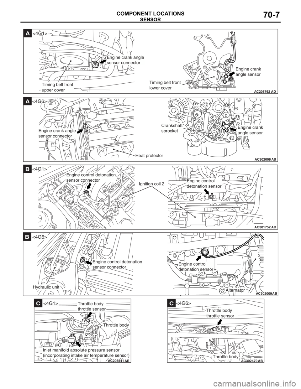
SENSOR
COMPONENT LOCA TIONS70-7
Page 402 of 800
EARTH CABLE
COMPONENT LOCATIONS70-12
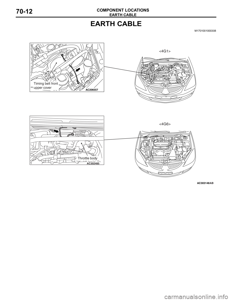
EARTH CABLE
M1701001000308
AC303148
AC206557
AC302485
AB
Timing belt front
upper cover
Throttle body
<4G1><4G6>