air cleaner MITSUBISHI LANCER IX 2006 Service Manual
[x] Cancel search | Manufacturer: MITSUBISHI, Model Year: 2006, Model line: LANCER IX, Model: MITSUBISHI LANCER IX 2006Pages: 800, PDF Size: 45.03 MB
Page 38 of 800
THERMOSTAT
ENGINE COOLING14-24
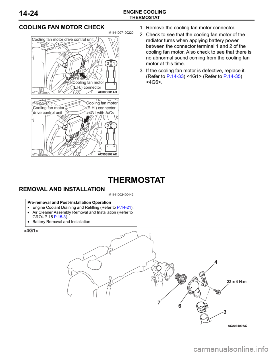
COOLING FAN MOTOR CHECK
M1141007100220
1
2
AC303501AB
Cooling fan motor drive control unit
Cooling fan motor
(L.H.) connector
1
2
AC303502AB
Cooling fan motor
drive control unit
Cooling fan motor
(R.H.) connector
<4G1 with A/C>
1. Remove the cooling fa n mot o r co nnector .
2.Check t o see that t he co oling fan motor of the
ra diato r turns wh en ap plying b a ttery power
b e tween th e con nect o r terminal 1 and 2 of t he
cooling fa n mo tor . Also ch eck to see tha t there is
n o abno rmal soun d co min g from the cooling fa n
motor a t this time.
3.If the cooling fan moto r is defective, replace it.
(Refe r to
P.14-33) <4G1> (Refer to P.14-35)
<4G6>.
THERMOSTA T
REMOVA L AND INST ALLA TION
M1141 0024 0044 2
Pre-removal and Post-installation Operation
•Engine Coolant Draining and Refilling (Refer to P.14-21).
•Air Cleaner Assembly Removal and Installation (Refer to
GROUP 15
P.15-3).
•Battery Removal and Installation
AC203409AC
4
3
6
7
22 ± 4 N·m
<4G1>
Page 43 of 800
WATER HOSE AND WATER PIPE
ENGINE COOLING14-29
WATER HOSE AND WATER PIPE
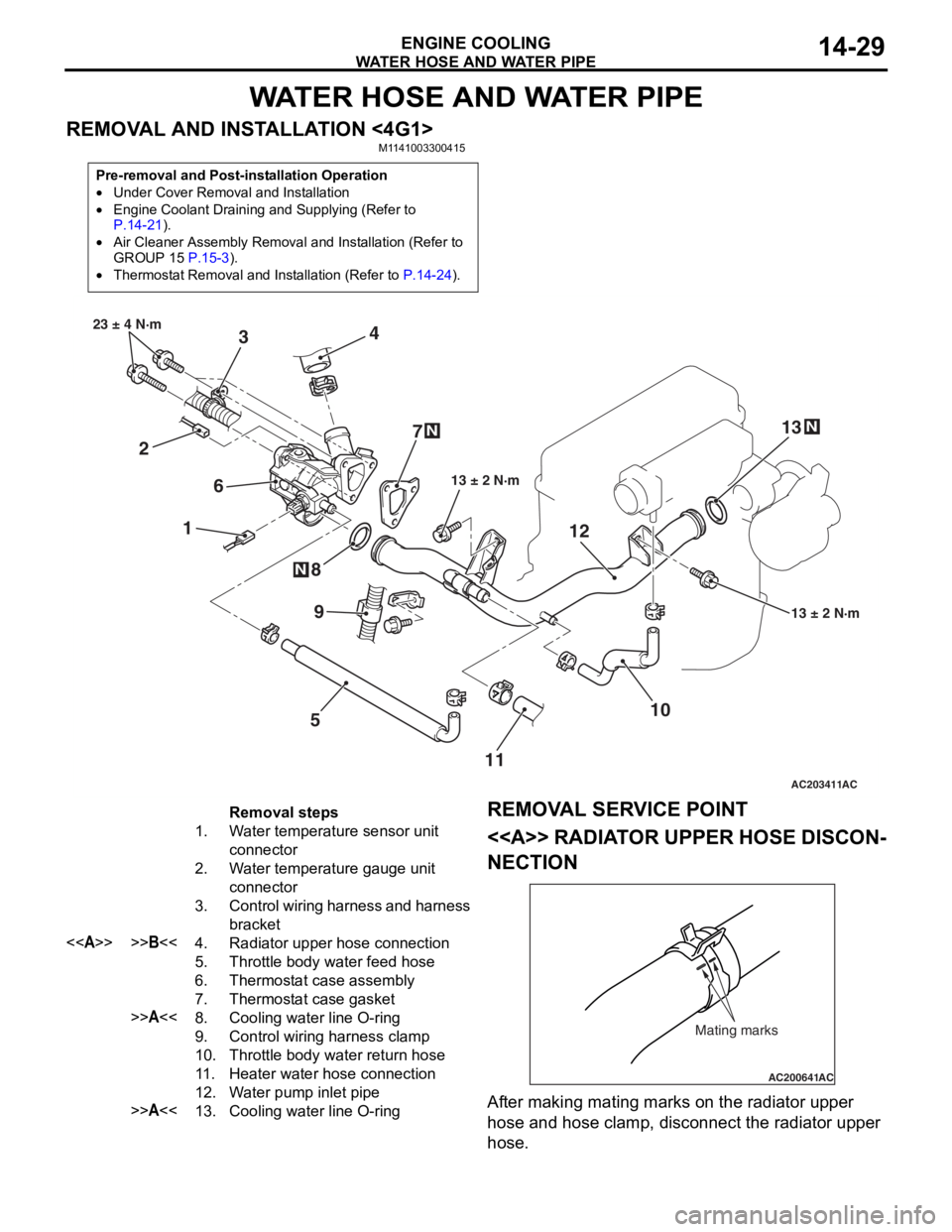
REMOVAL AND INSTALLATION <4G1>M1141003300415
Pre-removal and Post-installation Operation
•Under Cover Removal and Installation
•Engine Coolant Draining and Supplying (Refer to P.14-21).
•Air Cleaner Assembly Removal and Installation (Refer to
GROUP 15 P.15-3).
•Thermostat Removal and Installation (Refer to P.14-24).
AC203411
1
2 3
4
5
6
7
8
10
9
13 ± 2 N·m
23 ± 4 N·m
13 ± 2 N·m
N
N
AC
1112
13
N
Removal steps
1.Water temperature sensor unit
connector
2.Water temperature gauge unit
connector
3.Control wiring harness and harness
bracket
<>>>B<<4.Radiator upper hose connection
5.Throttle body water feed hose
6.Thermostat case assembly
7.Thermostat case gasket
>>A<<8.Cooling water line O-ring
9.Control wiring harness clamp
10.Throttle body water return hose
11 .Heater water hose connection
12.Water pump inlet pipe
>>A<<13.Cooling water line O-ring
REMOV
A L SER VICE POINT
<> RADIAT OR UPPER HOSE DISCON-
NECTION
AC200641AC
Mating marks
After making matin g ma rks on the radia t or upp er
hose
and h o se clamp, disconnect the radia t or upp er
hose
.
Page 45 of 800
WATER HOSE AND WATER PIPE
ENGINE COOLING14-31
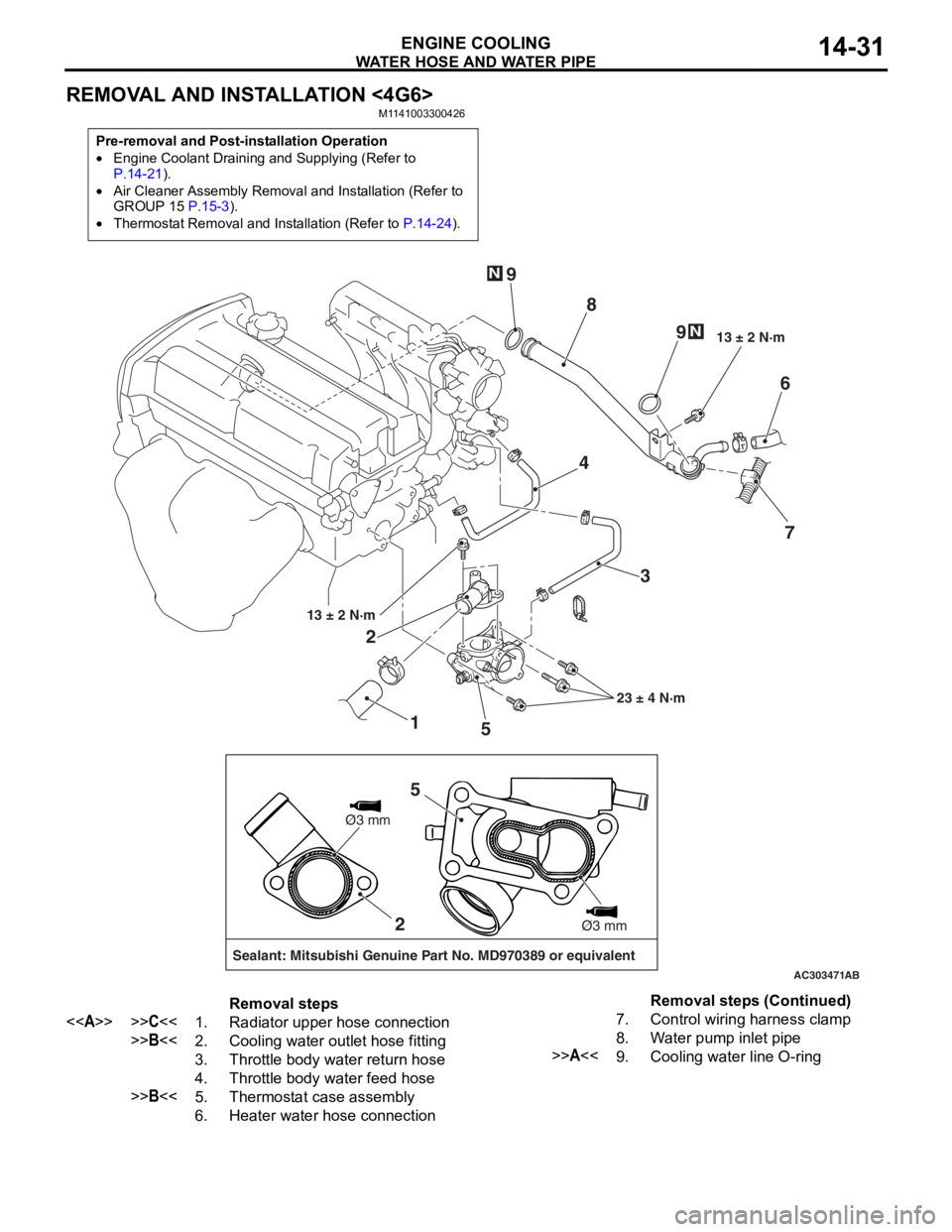
REMOVAL AND INSTALLATION <4G6>
M1141003300426
Pre-removal and Post-installation Operation
•Engine Coolant Draining and Supplying (Refer to P.14-21).
•Air Cleaner Assembly Removal and Installation (Refer to
GROUP 15 P.15-3).
•Thermostat Removal and Installation (Refer to P.14-24).
AC303471
1
2
3
4
5 6
7
8
9
9
13 ± 2 N·m
23 ± 4 N·m
13 ± 2 N·m
N
N
AB
2
Sealant: Mitsubishi Genuine Part No. MD970389 or equivalent
Ø3 mm
Ø3 mm
5
Removal steps
<>>>C<<1.Radiator upper hose connection
>>B<<2.Cooling water outlet hose fitting
3.Throttle body water return hose
4.Throttle body water feed hose
>>B<<5.Thermostat case assembly
6.Heater water hose connection
7.Control wiring harness clamp
8.Water pump inlet pipe
>>A<<9.Cooling water line O-ring
Removal steps (Continued)
Page 47 of 800
RADIATOR
ENGINE COOLING14-33
RADIATOR
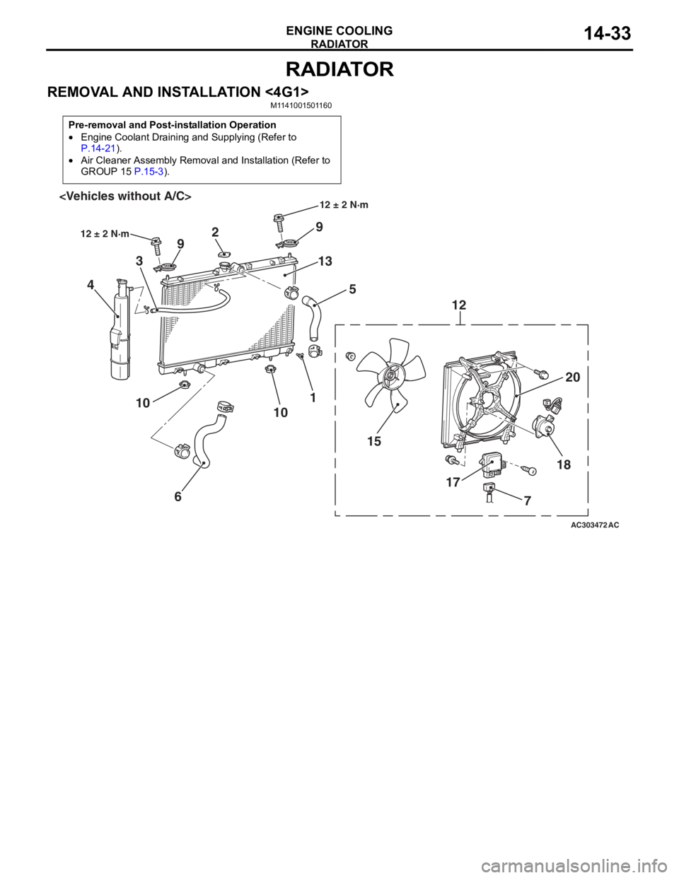
REMOVAL AND INSTALLATION <4G1>M1141001501160
Pre-removal and Post-installation Operation
•Engine Coolant Draining and Supplying (Refer to
P.14-21).
•Air Cleaner Assembly Removal and Installation (Refer to
GROUP 15
P.15-3).
AC303472
18
17
15 20
12
9
13 5
2
9
3
4
1
10
6
10
AC
12 ± 2 N·m
12 ± 2 N·m
7
Page 49 of 800
RADIATOR
ENGINE COOLING14-35
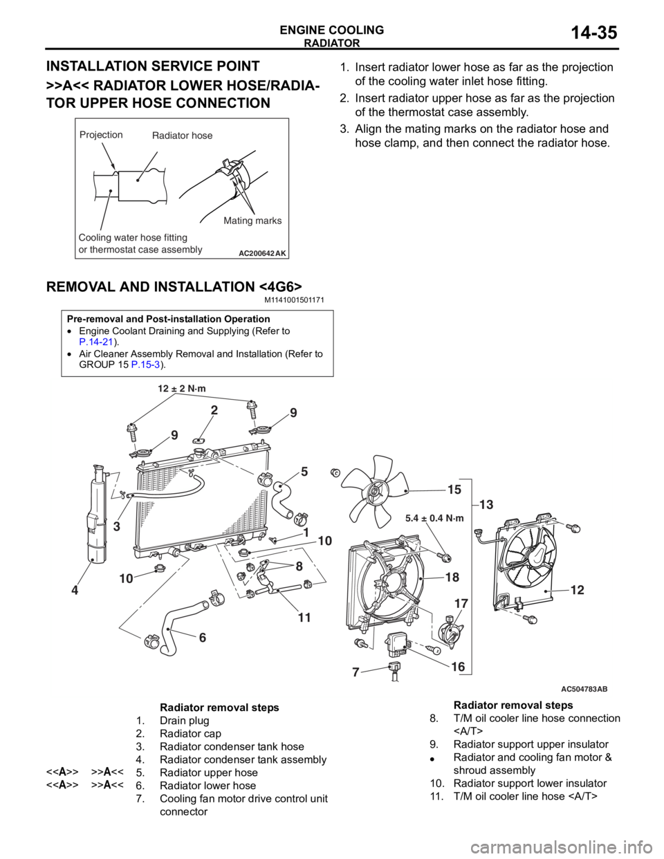
INSTALLATION SERVICE POINT
>>A<< RADIATOR LOWER HOSE/RADIA-
TOR UPPER HOSE CONNECTION
AC200642
Mating marks
Projection
Cooling water hose fitting
or thermostat case assembly
AK
Radiator hose
1.In sert ra diato r lower h o se as fa r as th e projection
o f the cooling wate r inlet hose fit t ing.
2.In sert radia t or up per h o se as far a s t he pro j ection
o f the th ermost at ca se asse mbly .
3.Align th e ma ting marks on the rad i ator hose and
h o se clamp, an d then conn ect the radiator h o se.
REMOVA L AND INST ALLA TION <4G6>
M11 4100 1501 17 1
Pre-removal and Post-installation Operation
•Engine Coolant Draining and Supplying (Refer to
P.14-21).
•Air Cleaner Assembly Removal and Installation (Refer to
GROUP 15
P.15-3).
AC504783
1
12 ± 2 N·m
10
2
3
4
5
6
7
8
9
9
10
11 13
15
18
16
17
12
AB
5.4 ± 0.4 N·m
Radiator removal steps
1.Drain plug
2.Radiator cap
3.Radiator condenser tank hose
4.Radiator condenser tank assembly
<>>>A<<5.Radiator upper hose
<>>>A<<6.Radiator lower hose
7.Cooling fan motor drive control unit
connector
8.T/M oil cooler line hose connection
9.Radiator support upper insulator
•Radiator and cooling fan motor &
shroud assembly
10.Radiator support lower insulator
11 .T/M oil cooler line hose
Radiator removal steps
Page 51 of 800
15-1
GROUP 15
INTAKE AND
EXHAUST
CONTENTS
GENERAL INFORMATIO N . . . . . . . .15-2
SERVICE SPECIFICATION . . . . . . . .15-2
SPECIAL TOOL . . . . . . . . . . . . . . . . .15-2
AIR CLEANER . . . . . . . . . . . . . . . . . .15-3
REMOVAL AND INSTALLATION . . . . . . . . 15-3
INLET MANIFOLD . . . . . . . . . . . . . . .15-5
REMOVAL AND INSTALLATION <4G1> . . 15-5
REMOVAL AND INSTALLATION <4G6> . . 15-6
INSPECTION. . . . . . . . . . . . . . . . . . . . . . . . 15-7
EXHAUST MANIFOLD . . . . . . . . . . . .15-7
REMOVAL AND INSTALLATION <4G1> . . 15-7
REMOVAL AND INSTALLATION <4G6> . . 15-9
INSPECTION. . . . . . . . . . . . . . . . . . . . . . . . 15-10
EXHAUST PIPE AND MAIN
MUFFLER . . . . . . . . . . . . . . . . . . . . . .15-10
REMOVAL AND INSTALLATION . . . . . . . . 15-10
Page 53 of 800
AIR CLEANER
INTAKE AND EXHAUST15-3
AIR CLEANER
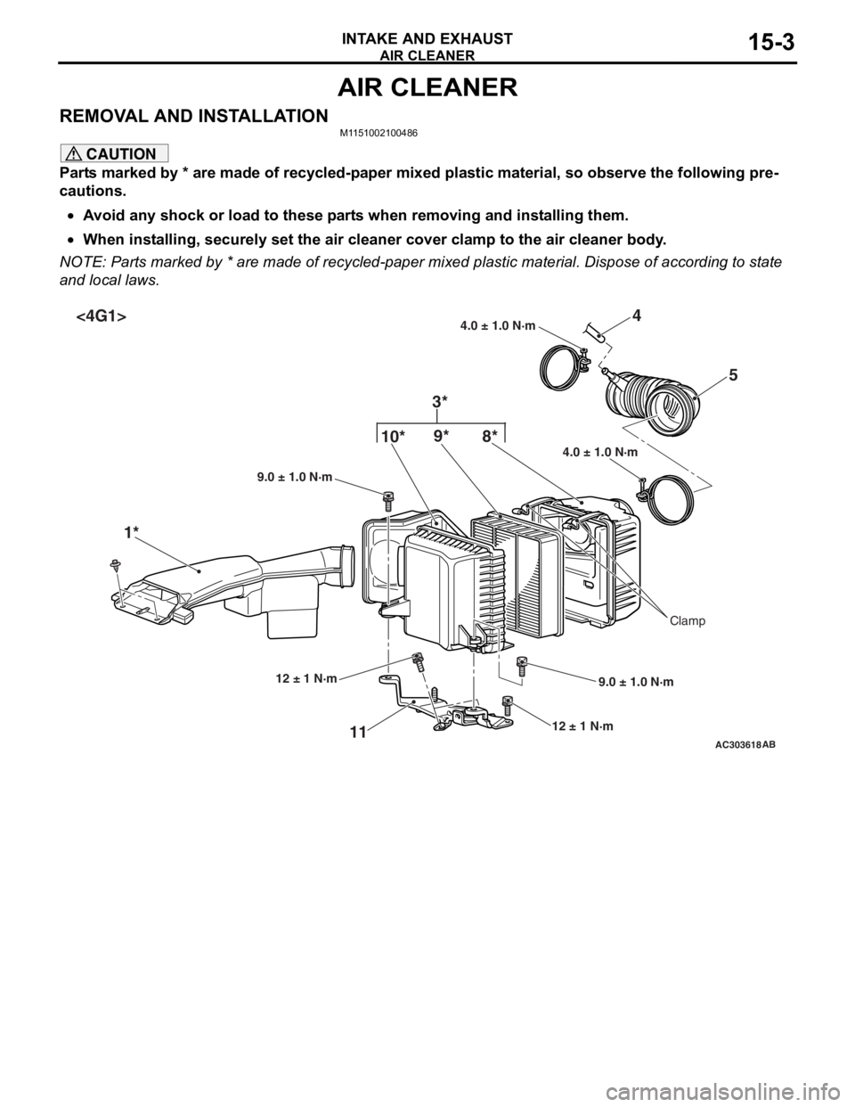
REMOVAL AND INSTALLATIONM1151002100486
CAUTION
Parts marked by * are made of recycled-paper mixed plastic material, so observe the following pre-
cautions.
•Avoid any shock or load to these parts when removing and installing them.
•When installing, securely set the air cleaner cover clamp to the air cleaner body.
NOTE: Parts marked by * are made of recycled-paper mixed plastic material. Dispose of according to state
and local laws.
AC303618
4.0 ± 1.0 N·m
4.0 ± 1.0 N·m
10*
9* 4
1* 5
11
12 ± 1 N·m 9.0 ± 1.0 N·m
9.0 ± 1.0 N·m
AB
12 ± 1 N·m
Clamp
8*
3*
<4G1>
Page 54 of 800
AC303619
4.0 ± 1.0 N·m
4.0 ± 1.0 N·m10*
9* 4
1* 5
11
12 ± 1 N·m 9.0 ± 1.0 N·m
9.0 ± 1.0 N·m
AB
12 ± 1 N·m
Clamp
8*
3*
<4G6>
6
7
N
2
8.8 ± 1.0 N·m
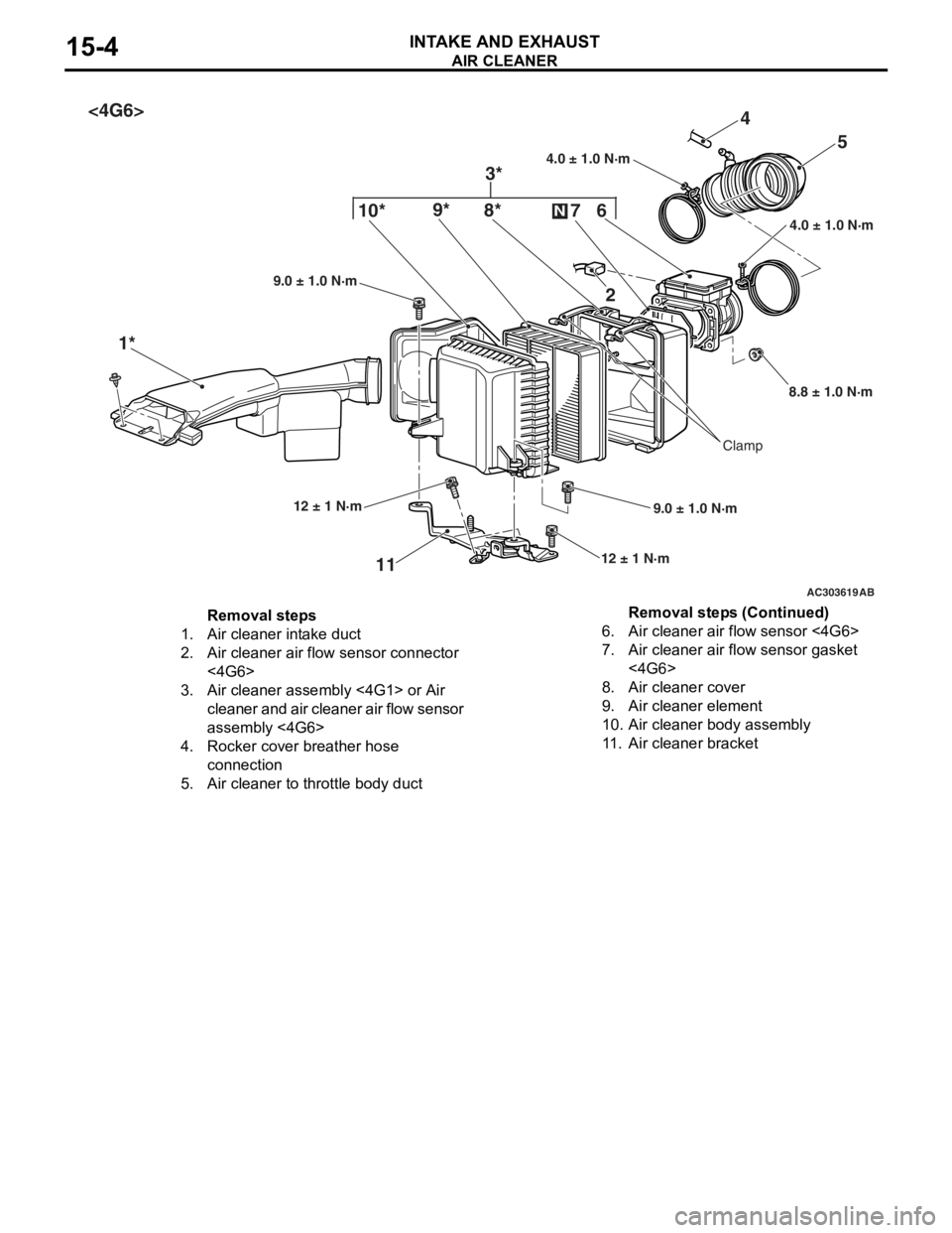
Removal steps
1.Air cleaner intake duct
2.Air cleaner air flow sensor connector
<4G6>
3.Air cleaner assembly <4G1> or Air
cleaner and air cleaner air flow sensor
assembly <4G6>
4.Rocker cover breather hose
connection
5.Air cleaner to throttle body duct
6.Air cleaner air flow sensor <4G6>
7.Air cleaner air flow sensor gasket
<4G6>
8.Air cleaner cover
9.Air cleaner element
10.Air cleaner body assembly
11 .Air cleaner bracket
AIR CLEA NER
INTAKE AN D EXHAU ST15-4
Removal steps (Continued)
Page 75 of 800
CHARGING SYSTEM
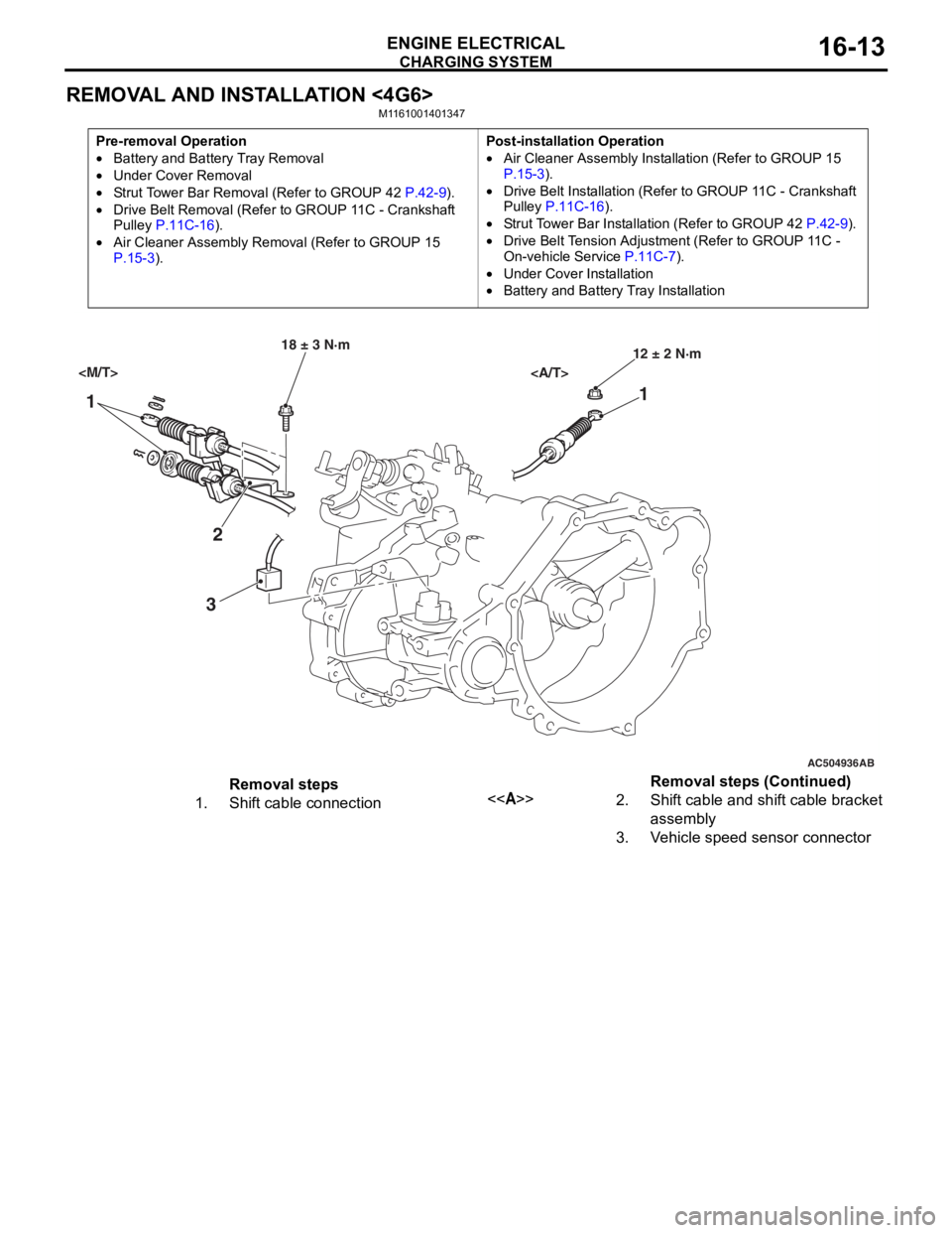
ENGINE ELECTRICAL16-13
REMOVAL AND INSTALLATION <4G6>
M1161001401347
Pre-removal Operation
•Battery and Battery Tray Removal
•Under Cover Removal
•Strut Tower Bar Removal (Refer to GROUP 42 P.42-9).
•Drive Belt Removal (Refer to GROUP 11C - Crankshaft
Pulley P.11C-16).
•Air Cleaner Assembly Remo val (Refer to GROUP 15 P.15-3).
Post-installation Operation
•Air Cleaner Assembly Installation (Refer to GROUP 15 P.15-3).
•Drive Belt Installation (Refer to GROUP 11C - Crankshaft
Pulley P.11C-16).
•Strut Tower Bar Installation (Refer to GROUP 42 P.42-9).
•Drive Belt Tension Adjustment (Refer to GROUP 11C -
On-vehicle Service
P.11C-7).
•Under Cover Installation
•Battery and Battery Tray Installation
AC504936
1 1
2
3
18 ± 3 N·m 12 ± 2 N·m
AB
Removal steps
1.Shift cable connection<>2.Shift cable and shift cable bracket
assembly
3.Vehicle speed sensor connector
Removal steps (Continued)
Page 83 of 800
STARTING SYSTEM
ENGINE ELECTRICAL16-21
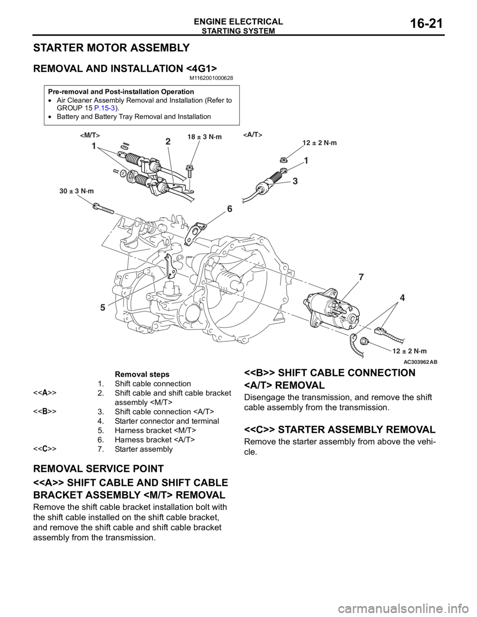
STARTER MOTOR ASSEMBLY
REMOVAL AND INSTALLATION <4G1>
M1162001000628
Pre-removal and Post-installation Operation
•Air Cleaner Assembly Removal and Installation (Refer to
GROUP 15 P.15-3).
•Battery and Battery Tray Removal and Installation
AC303962AB
11
2
3
5 6
74
30 ± 3 N·m 18 ± 3 N·m
12 ± 2 N·m
12 ± 2 N·m
Removal steps
1.Shift cable connection
<>2.Shift cable and shift cable bracket
assembly
<>3.Shift cable connection
4.Starter connector and terminal
5.Harness bracket
6.Harness bracket
<
REMOVA L SER V ICE POINT
<> SHIFT CABLE AND SHIFT CABLE
BRACKET ASSEMBL
Y
Remove the shift cable bracket inst allation bolt with
the shif
t ca ble inst alled o n the shif t cable bracket,
and remove
the shif t cable and shif t cable bracket
assembly fro
m the transmission.
<> SHIFT CABLE CONNECTION
REMOVA L
Disengage th e transmission, a nd remove the shif t
cable assembly from the tra
n smission .
<
Remove the st arter assembly from above the veh i-
cle.