remote control MITSUBISHI LANCER IX 2006 Service Manual
[x] Cancel search | Manufacturer: MITSUBISHI, Model Year: 2006, Model line: LANCER IX, Model: MITSUBISHI LANCER IX 2006Pages: 800, PDF Size: 45.03 MB
Page 375 of 800
DOOR MIRROR
EXTERIOR51-43
DOOR MIRROR
GENERAL INFORMATIONM1511000100536
DOOR MIRROR OPERATION
Remote Controlled Mirror Operation
•The mirror on the door mirror moves up/down
and left/right by operating the remote controlled
door mirror switch when the ignition switch is in
the "ON" or "ACC" position.
Heated Door Mirror operation
•The defogger relay switch is activated (ON) by
turning on the A/C-ECU built-in defogger switch
when the ignition switch is in the "ON" position.
When the defogger relay is turned ON, power is
supplied to the defogger and door mirror, and the
heater of the door mirror (heated door mirror)
starts operations. The defogger comes with a
timer function and will automatically turn OFF the
switch approximately 11 minutes after the defog
-
ger switch is turned ON. The heated door mirror
operations are also terminated along with the
defogger, at this time.
SERVICE SPECIFICATION
M1511000300347
ItemStandard value
Heated door mirror operation current Ω5.9 − 7.8
SPECIAL TOOL
M1511000601103
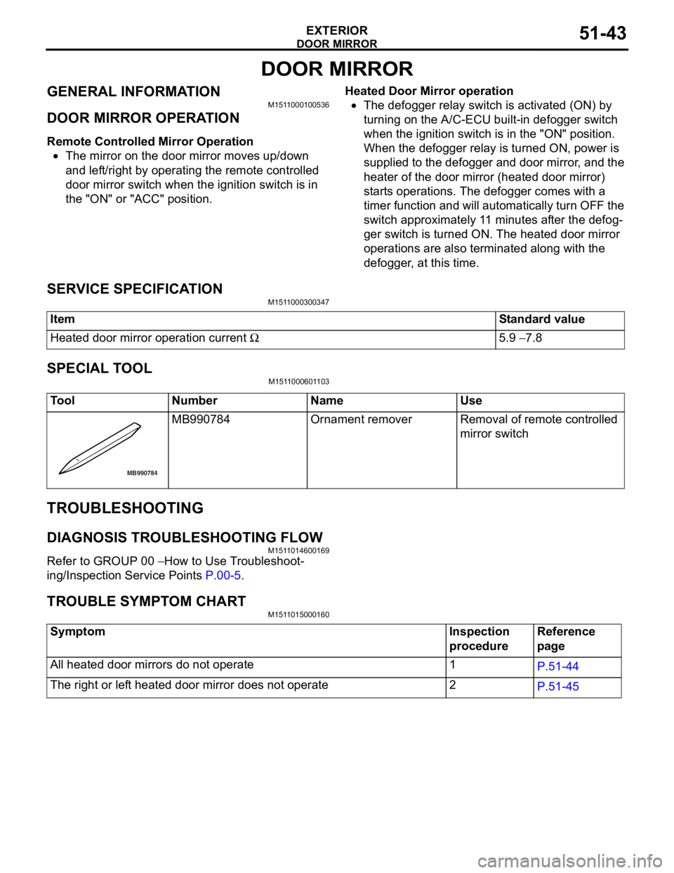
ToolNumberNameUse
MB990784
MB990 784Ornament removerRemoval of remote controlled
mirror switch
TROUBLESHOOTING
DIAGNOSIS TROUBLESHOOTING FLOW
M151 1 0146 0016 9
Refe r to GROUP 00 − How to Use T r o ubleshoot-
ing/Inspectio n Service Point s P.00-5.
TR OUBLE SYM PT OM CHARTM151 1 0150 0016 0
SymptomInspection
procedureReference
page
All heated door mirrors do not operate1P.51-44
The right or left heated door mirror does not operate2P.51-45
Page 376 of 800
DOOR MIRROR
EXTERIOR51-44
SYMPTOM PROCEDURES
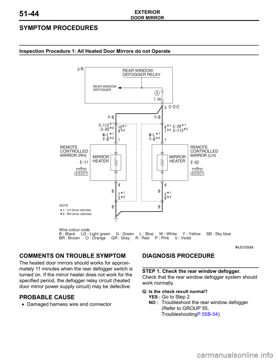
Inspection Procedure 1: All Heated Door Mirrors do not Operate
Wire colour code
B : Black LG : Light green G : Green L : Blue W : White \
Y : Yellow SB : Sky blue
BR : Brown O : Orange GR : Gray R : Red P : Pink V :\
Violet REAR WINDOW
DEFOGGER RELAY
REAR WINDOW
DEFOGGER
REMOTE
CONTROLLED
MIRROR (LH)
REMOTE
CONTROLLED
MIRROR (RH)
MIRROR
HEATER MIRROR
HEATER
NOTELH drive vehicles
RH drive vehicles
COMM
ENT S ON TROUBL E SYMPT O M
The heated do or mirrors shou ld works for approxi-
mately 11 minu tes whe n the re ar defo gger switch is
turned o
n . If th e mirror hea ter doe s no t work fo r the
specified period, th
e defo gger relay circuit (heated
door mirror p
o wer sup p ly circuit) may be d e fective .
PROBABLE CAUSE
•Damaged h a rness wire and connector
DIAGNOSIS PROCEDURE
STEP 1 . Check the rear wind ow de fogger .
Check that th e rear window def ogger system shou ld
wo
rk normally .
Q:Is t h e che c k r esu lt n o rmal?
YES : Go to S t ep 2 .
NO : Tr oublesh oot the rear win dow defog ger
(Refer to
GROUP 55 ,
T
r oublesh ootin g
P.55B-54).
Page 377 of 800
DOOR MIRROR
EXTERIOR51-45
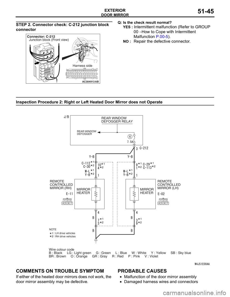
STEP 2. Connector check: C-212 junction block
connector
AC304913
21716151718
201912345
623 222425282627981011141213
Connector: C-212
Harness side
AB
Junction block (Front view)
Q: Is t h e che c k r esu lt n o rmal?
YES : Intermittent malfun ctio n (Refer to GROUP
00
− Ho w to Cope wit h Intermitte nt
Ma
lfunction
P.00-5).
NO : Repa ir th e defective connector .
Inspection Procedure 2 : Ri ght or Lef t Hea t ed Door Mirror does not Operate
Wire colour code
B : Black LG : Light green G : Green L : Blue W : White \
Y : Yellow SB : Sky blue
BR : Brown O : Orange GR : Gray R : Red P : Pink V :\
Violet REAR WINDOW
DEFOGGER RELAY
REAR WINDOW
DEFOGGER
REMOTE
CONTROLLED
MIRROR (LH)
REMOTE
CONTROLLED
MIRROR (RH)
MIRROR
HEATER MIRROR
HEATER
NOTELH drive vehicles
RH drive vehicles
COMM
ENT S ON TROUBL E SYMPT O M
If eit her of t he hea ted d oor mirrors does n o t work, the
door mirror a
sse mbly may b e defe c tive.
PROBABLE CAUSES
•Malfunctio n of th e door mirro r assemb ly
•Damaged ha rness wires and con necto rs
Page 382 of 800
DOOR MIRROR
EXTERIOR51-50
DOOR MIRROR
REMOVAL AND INSTALLATION
M1511006400308
AC304733
Note
: Claw positions
AB
AA
Section A – A
Claw1
2
12 3 4
5
6
7
8
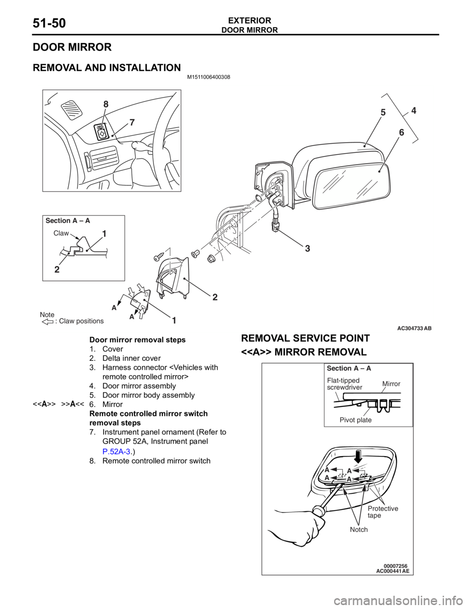
Door mirror removal steps
1.Cover
2.Delta inner cover
3.Harness connector
4.Door mirror assembly
5.Door mirror body assembly
<>>>A<<6.Mirror
Remote controlled mirror switch
removal steps
7.Instrument panel ornament (Refer to
GROUP 52A, Instrument panel
P.52A-3.)
8.Remote controlled mirror switch
REMOV
A L SER VICE POINT
<> MIRROR REMOV A L
AC00044100007256
Mirror
Flat-tipped
screwdriver
Section A – A
Pivot plate
Notch
Protective
tape
A
A A
A
AE
Page 383 of 800

DOOR MIRROR
EXTERIOR51-51
Push the top of the mirror with your hand to tilt it and
attach the protective tape as shown in the illustration.
Then insert a flat-tipped screwdriver in between the
notch at the rear of the mirror and the pivot plate, and
disengage the bottom of the mirror.
INSTALLATION SERVICE POINT
>>A<< MIRROR INSTALLATION
AC00044200007258
Mirror
Flat-tipped
screwdriver
Section A – A
Pivot plate
A
A A
A
AB
W h il e su pp ort i ng t he clip po siti on on th e u nde rsi de of
the pivot p
l ate with a flat -tipped screwdr i ver , press
t
he clip at th e front of the mirror t o engage t he botto m
of the mirro
r .
INSPECTION
M151 1 0065 0028 6
ELECTRIC REMOTE CONTROL MIRROR
OPERA
T ION CHECK < V EHICLES WITH
-
OUT HEAT ED DOOR MIRROR>
3
2
1
AC005969
Ch eck that th e mirror moves as describe d in the
t
a b l e when each terminal is conn ecte d to the batte ry .
Battery connectionDirection
operation
•Connect terminal 1 to the negative
battery terminal.
•Connect terminal 3 to the positive
battery terminal.
Mirror
glass
should face
upward
•Connect terminal 3 to the negative
battery terminal.
•Connect terminal 1 to the positive
battery terminal.
Mirror
glass
should face
downward
•Connect terminal 1 to the negative
battery terminal.
•Connect terminal 2 to the positive
battery terminal.
Mirror
glass
should face
to the right
•Connect terminal 2 to the negative
battery terminal.
•Connect terminal 1 to the positive
battery terminal.
Mirror
glass
should face
to the left
Page 384 of 800
DOOR MIRROR
EXTERIOR51-52
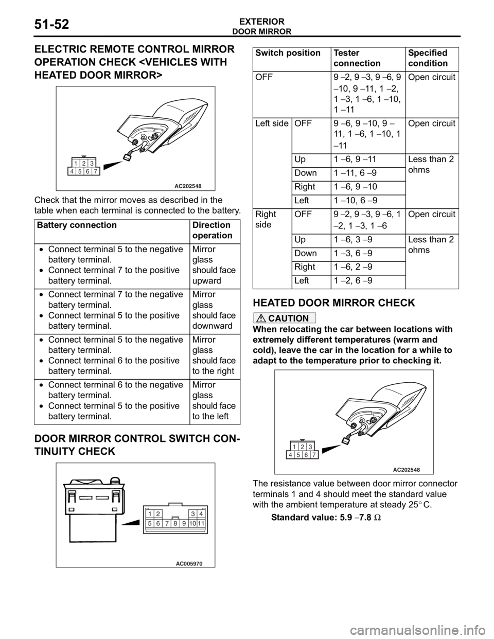
ELECTRIC REMOTE CONTROL MIRROR
OPERATION CHECK
AC202548
1
4567 23
Che
c k that th e mirror moves as describe d in the
t
a b l e when each terminal is conn ecte d to the batter y .
Battery connectionDirection
operation
•Connect terminal 5 to the negative
battery terminal.
•Connect terminal 7 to the positive
battery terminal.
Mirror
glass
should face
upward
•Connect terminal 7 to the negative
battery terminal.
•Connect terminal 5 to the positive
battery terminal.
Mirror
glass
should face
downward
•Connect terminal 5 to the negative
battery terminal.
•Connect terminal 6 to the positive
battery terminal.
Mirror
glass
should face
to the right
•Connect terminal 6 to the negative
battery terminal.
•Connect terminal 5 to the positive
battery terminal.
Mirror
glass
should face
to the left
DOOR MIRROR CONTROL SWITCH CON-
TINUITY CHECK
AC005970
2
14
3
510 9
8
7
6
11
Switch positionTester
connectionSpecified
condition
OFF9 − 2, 9 − 3, 9 − 6, 9
− 10, 9 − 11, 1 − 2,
1
− 3, 1 − 6, 1 − 10,
1
− 11
Open circuit
Left sideOFF9 − 6, 9 − 10, 9 −
11 , 1
− 6, 1 − 10, 1
− 11
Open circuit
Up1 − 6, 9 − 11Less than 2
ohms
Down1 − 11, 6 − 9
Right1 − 6, 9 − 10
Left1 − 10, 6 − 9
Right
sideOFF9 − 2, 9 − 3, 9 − 6, 1
− 2, 1 − 3, 1 − 6
Open circuit
Up1 − 6, 3 − 9Less than 2
ohms
Down1 − 3, 6 − 9
Right1 − 6, 2 − 9
Left1 − 2, 6 − 9
HEA T ED DOOR MIRROR CHECK
CAUTION
When relocating the car between locations with
extremely different temperatures (warm and
cold), leave the car in the location for a while to
adapt to the temperature prior to checking it.
AC202548
1
4567 23
The resistance value between door mirror connector
terminals 1 and 4 should meet the standard value
with the ambient temperature at steady 25
°C.
Standard value: 5.9 − 7.8 Ω
Page 437 of 800
AC502052AB
5
14
15
C-08C-39C-09
C-11C-12
C-10
C-14
C-15
C-13
Instrument panel
wiring harness
Control wiring
harness
C-19
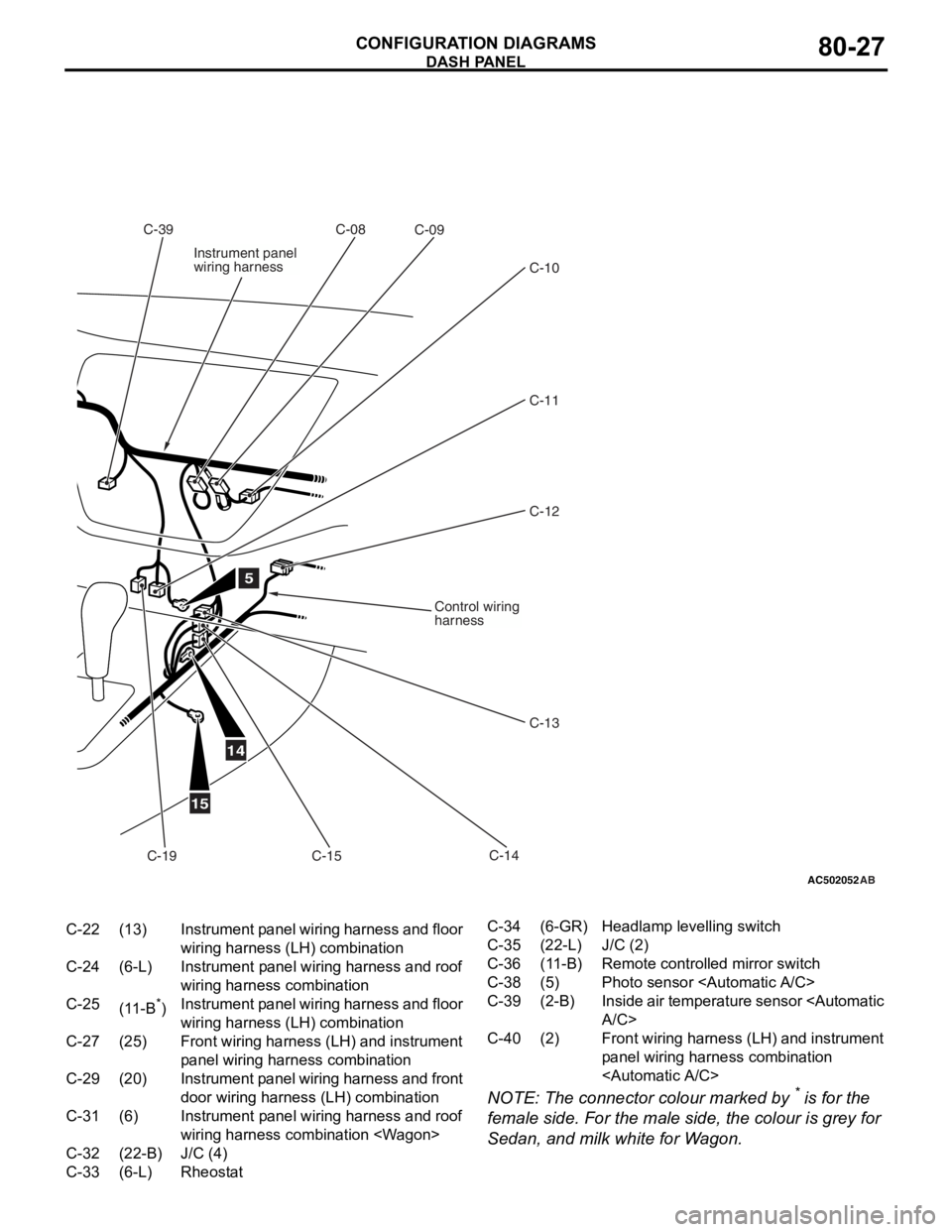
C-22(13)Instrument panel wiring harness and floor
wiring harness (LH) combination
C-24(6-L)Instrument panel wiring harness and roof
wiring harness combination
C-25(11-B*)Instrument panel wiring harness and floor
wiring harness (LH) combination
C-27(25)Front wiring harness (LH) and instrument
panel wiring harn ess combination
C-29(20)Instrument panel wiring harness and front
door wiring harness (LH) combination
C-31(6)Instrument panel wiring harness and roof
wiring harness combination
C-32(22-B)J/C (4)
C-33(6-L)Rheostat
C-34(6-GR)Headlamp levelling switch
C-35(22-L)J/C (2)
C-36(11-B)Remote controlled mirror switch
C-38(5)Photo sensor
C-39(2-B)Inside air temperature sensor
C-40(2)Front wiring harness (LH) and instrument
panel wiring harness combination
DASH P ANEL
CONF IGURA TION D I A G RA MS80-27
NOTE: The conn ecto r colour marked by * is fo r the
female side. F
o
r the male
side, the
colour is grey for
Se
dan, a
nd milk white f
o
r W
a
g
on.
Page 443 of 800
AC502056
C-39
AB
C-04 C-07 C-06 C-05 C-02 C-01J/B C-34
C-33
C-31
C-30
C-28
C-26
C-23 C-24
C-20 C-32
C-35
2
C-36
6
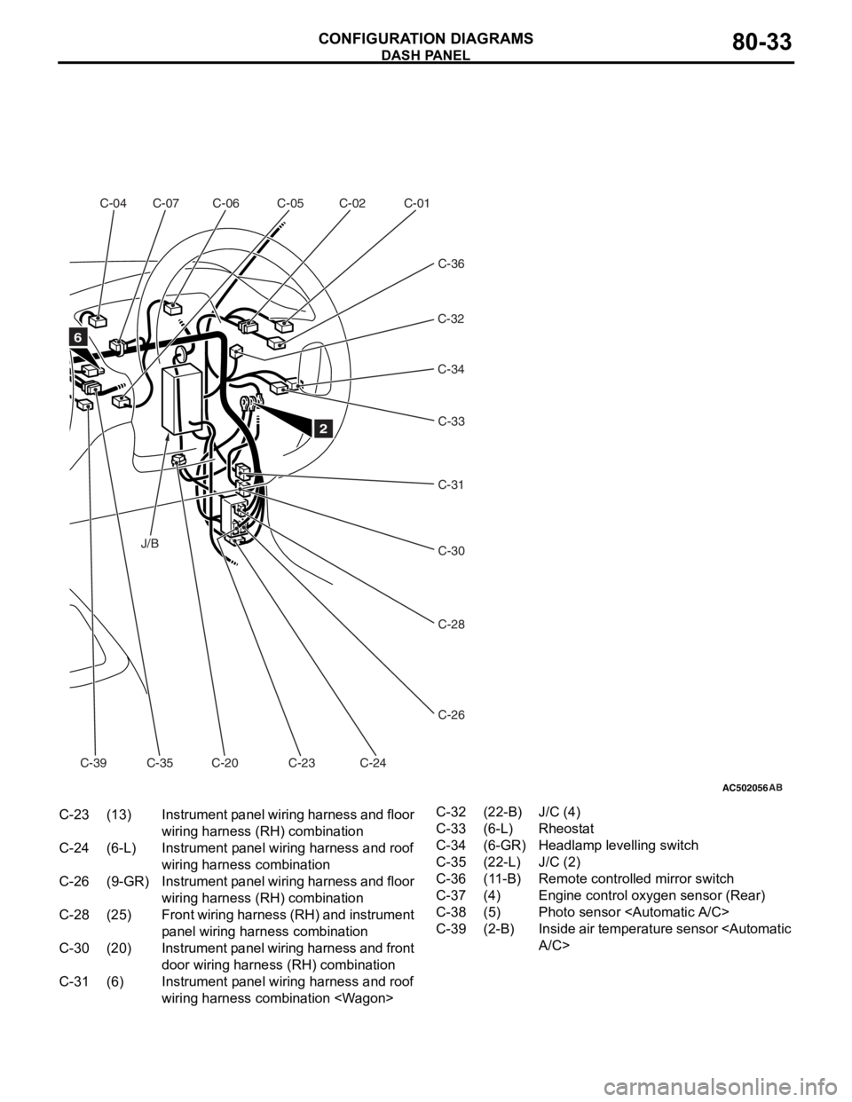
C-23(13)Instrument panel wiring harness and floor
wiring harness ( RH) combination
C-24(6-L)Instrument panel wiring harness and roof
wiring harness combination
C-26(9-GR)Instrument panel wiring harness and floor
wiring harness (RH) combination
C-28(25)Front wiring harness (RH) and instrument
panel wiring harn ess combination
C-30(20)Instrument panel wiring harness and front
door wiring harness (RH) combination
C-31(6)Instrument panel wiring harness and roof
wiring harness combination
C-32(22-B)J/C (4)
C-33(6-L)Rheostat
C-34(6-GR)Headlamp levelling switch
C-35(22-L)J/C (2)
C-36(11-B)Remote controlled mirror switch
C-37(4)Engine control oxygen sensor (Rear)
C-38(5)Photo sensor
C-39(2-B)Inside air temperature sensor
DASH P ANEL
CONF IGURA TION D I A G RA MS80-33
Page 456 of 800
DOOR
CONFIGURATION DIAGRAMS80-46
DOOR
DOOR
AC301826
Connector
symbol
E
Driver's sideE-01
E-02E-03
E-04
E-05
E-06
E-07
E-08
E-09
Front
Rear
AB
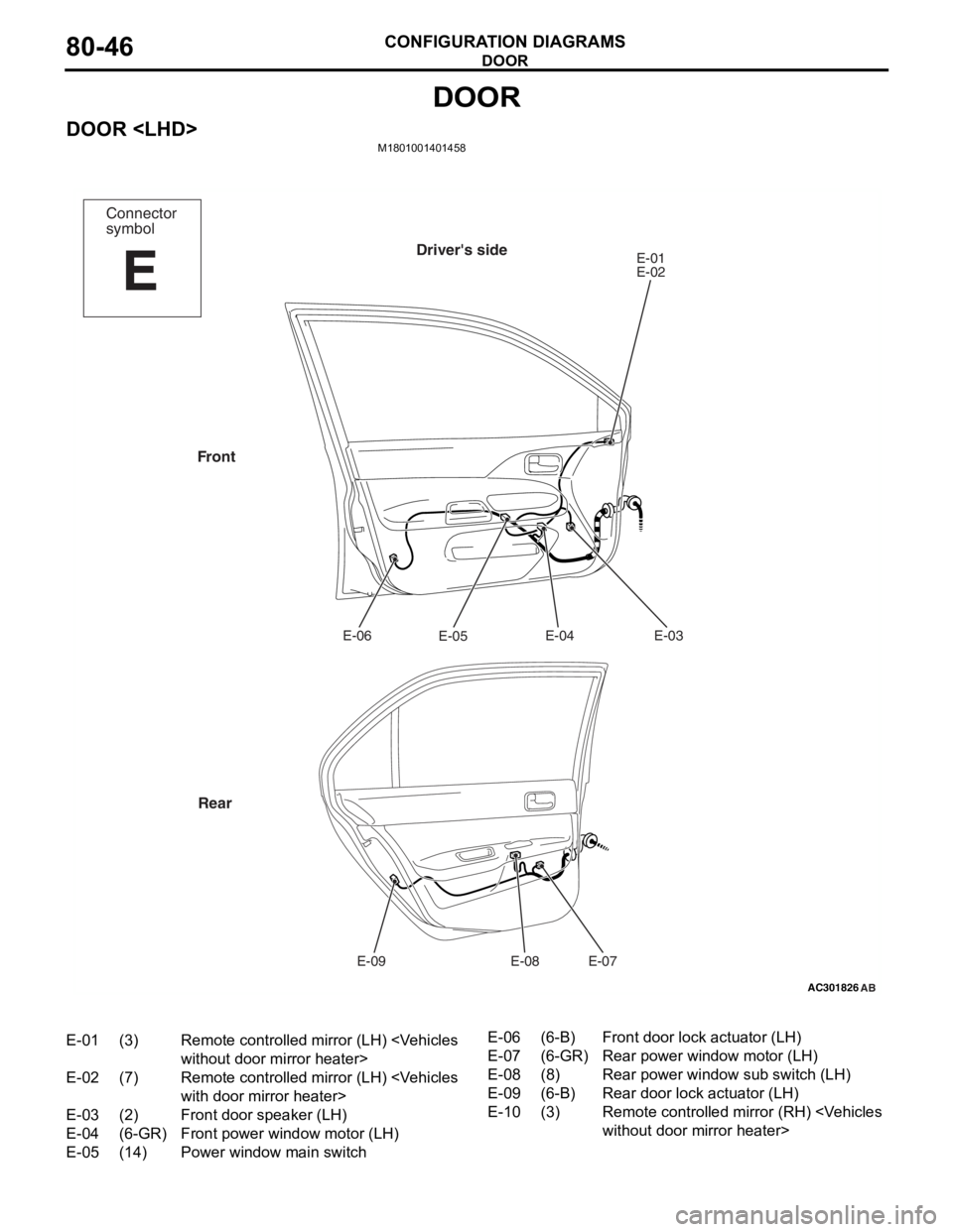
E-01(3)Remote controlled mirror (LH)
E-02(7)Remote controlled mirror (LH)
E-03(2)Front door speaker (LH)
E-04(6-GR)Front power window motor (LH)
E-05(14)Power window main switch
E-06(6-B)Front door lock actuator (LH)
E-07(6-GR)Rear power window motor (LH)
E-08(8)Rear power window sub switch (LH)
E-09(6-B)Rear door lock actuator (LH)
E-10(3)Remote controlled mirr or (RH)
Page 457 of 800
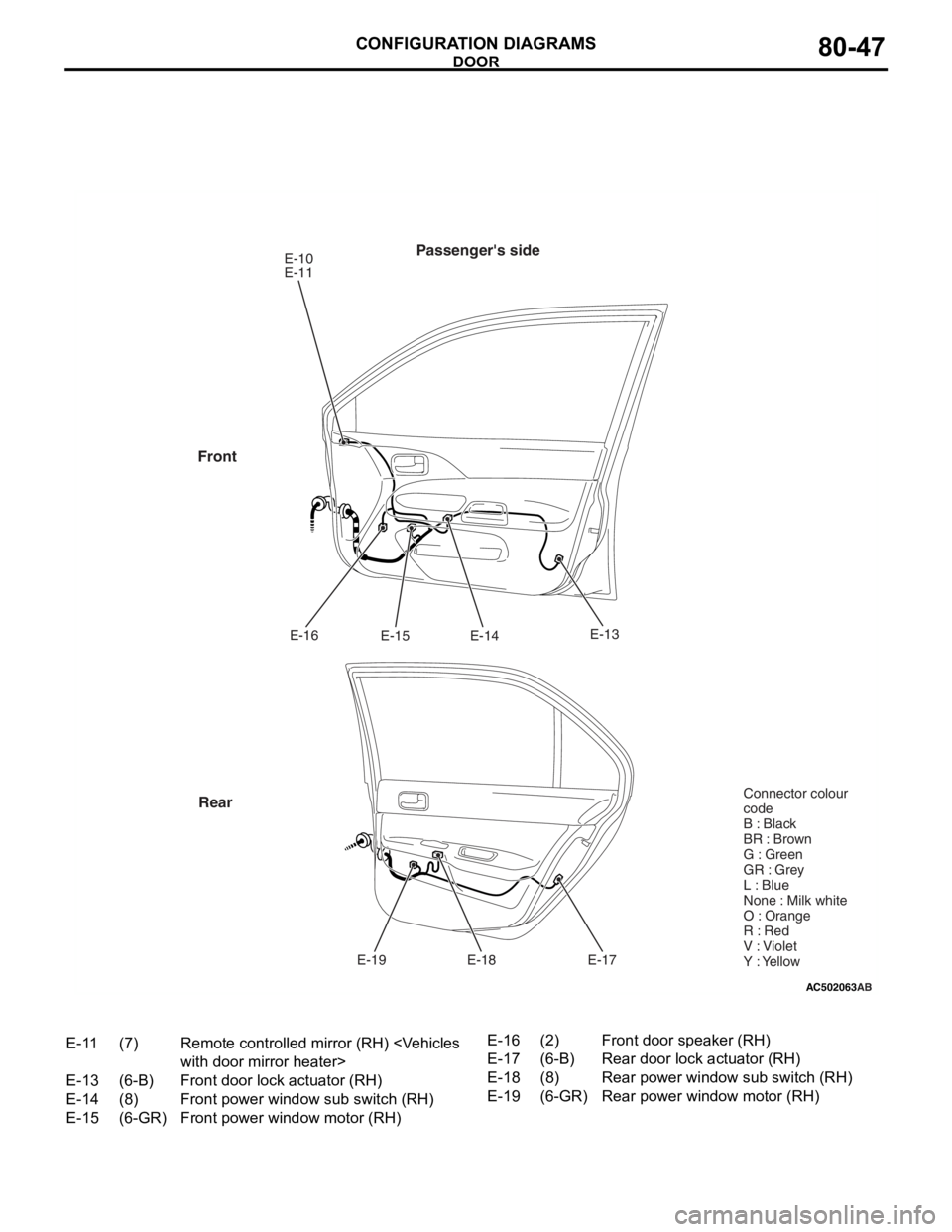
AC502063
Passenger's sideE-10
E-11E-14
E-15
E-16
E-17
E-18
E-19
Front
Rear
AB
E-13 Connector colour
code
B : Black
BR : Brown
G : Green
GR : Grey
L : Blue
None : Milk white
O : Orange
R : Red
V : Violet
Y : Yellow
E-11(7)Remote controlled mirror (RH)
E-13(6-B)Front door lock actuator (RH)
E-14(8)Front power window sub switch (RH)
E-15(6-GR)Front power window motor (RH)
E-16(2)Front door speaker (RH)
E-17(6-B)Rear door lock actuator (RH)
E-18(8)Rear power window sub switch (RH)
E-19(6-GR)Rear power window motor (RH)
DOOR
CONF IGURA TION D I A G RA MS80-47