run flat MITSUBISHI LANCER IX 2006 Service Manual
[x] Cancel search | Manufacturer: MITSUBISHI, Model Year: 2006, Model line: LANCER IX, Model: MITSUBISHI LANCER IX 2006Pages: 800, PDF Size: 45.03 MB
Page 163 of 800

31-1
GROUP 31
WHEEL AND TYRE
CONTENTS
GENERAL INFORMATION . . . . . . . .31-2
SERVICE SPECIFICATIONS . . . . . . .31-2
TROUBLESHOOTING . . . . . . . . . . . .31-3
DIAGNOSIS . . . . . . . . . . . . . . . . . . . . . . . . 31-3
WHEEL BALANCE ACCURACY . . . . . . . . 31-4
ON-VEHICLE SERVICE . . . . . . . . . . .31-7
TYRE INFLATION PRESSURE CHECK . . . 31-7
TYRE WEAR CHECK . . . . . . . . . . . . . . . . . 31-7
WHEEL RUNOUT CHECK . . . . . . . . . . . . . 31-7
WHEEL AND TYRE . . . . . . . . . . . . . .31-7
INSTALLATION SERVICE POINT . . . . . . . 31-7
Page 169 of 800

ON-VEHICLE SERVICE
WHEEL AND TYRE31-7
ON-VEHICLE SERVICE
TYRE INFLATION PRESSURE CHECKM1311000900312
NOTE: For information on tyre inflation pressure,
refer to the label attached to the centre pillar on the
driver's side.
TYRE WEAR CHECK
M1311001000334
Measure the tread depth of the tyres.
Minimum limit: 1.6 mm
If the remaining tread depth is less than the minimum
limit, replace the tyre.
NOTE: When the tread depth of the tyres is reduced
to 1.6 mm or less, wear indicators will appear.
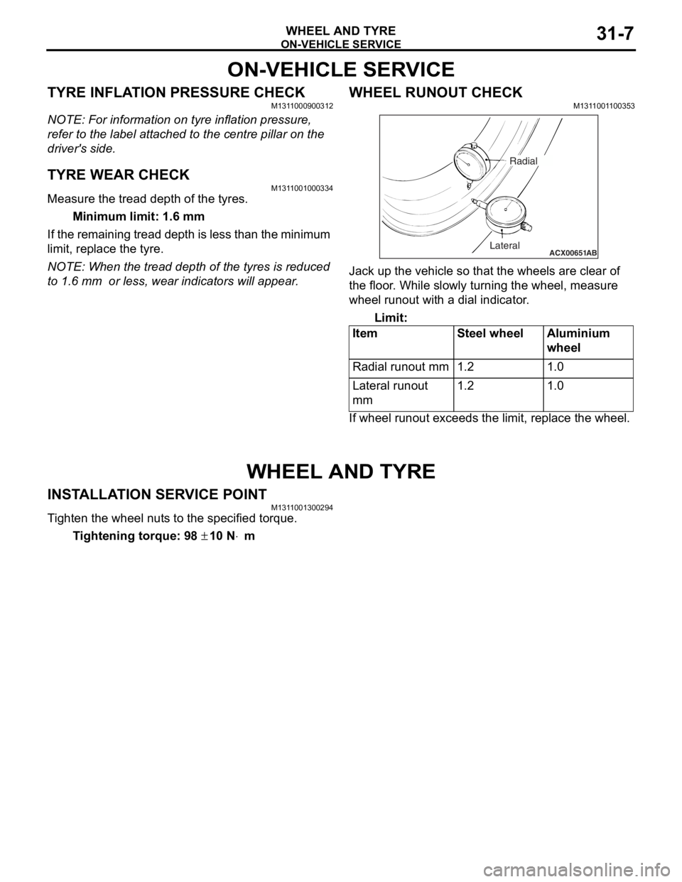
WHEEL RUNOUT CHECKM1311001100353
ACX00651 ABLateralRadial
Jack up
the vehicle so tha t the whe e ls are clear o f
the floor
. Wh ile slo w ly tur n ing the wheel, me asure
wh
eel ru nout wit h a dial indicator .
Limit:
ItemSt e e l wheelAluminium
whee
l
Radial runout mm1.21.0
Lateral runou t
mm1.21.0
If wheel runout exceeds the limit, rep l ace the whe e l.
WHEEL AND TYRE
INSTALLA T ION SER VICE POINTM131 1 0013 0029 4
Ti ghten the whee l nut s to the specified torq ue.
Ti ghte n ing torque: 98 ± 10 N⋅m
Page 223 of 800

LUBRICANTS
PARKING BRAKES36-3
LUBRICANTS
M1361000400293
ItemSpecified lubricant
Rear brake shoe and backing plate contact surfaceBrake grease SAE J310, NLGI No.1
Rear brake shoe assembly
Rear brake shoe slack adjuster
ON-VEHIC LE SER VI CE
PARKING BRAKE LE VER STROKE
CHECK AND ADJUSTMENT
M13610009 0033 9
1.Pull the p a rkin g brake le ver wit h a force of
ap proxima t ely 200 N an d co unt the number of
no tche s.
St andard va lue: 5 − 7 notches
2.If the p a rking b r ake leve r stro ke is no t the
st a ndard valu e, adjust as de scribed below .
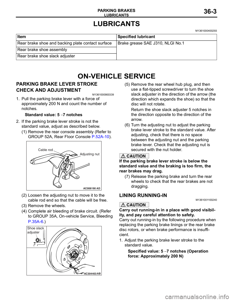
(1)R emove the rear console a sse mbly (Refer to
GROUP 5 2 A, Rear Floor Console
P.52A-10).
AC006190
Cable rod
Adjusting nut
AD
(2)Loosen th e adjusting nu t to move it to th e
cab l e rod end so tha t the cable will be fre e .
(3)R emove the wheels.
(4)C omplete a i r bleedin g of b r ake circuit. (Re f er
to GROUP 35A, On-ve h icle Service, Blee ding
P.35A-6.)
AC304403AB
Shoe slack
adjuster
(5
) R emove the rear whee l hub plug , and then
use a flat-tipped screwdriver to turn the shoe
slack ad juster in the direction of the arrow (the
dire ctio n which exp a nds the shoe) so that the
disc will no t rot a te.
Return the sh oe slack adjust e r 5 not ches in
the d
i rection opposite t o the d i rection of the
arrow
.
(6) T urn th e adjusting nut to adjust the p a rking
brake le ver stroke to the st anda rd value. Af ter
adjusting, check that there is n o sp ace
between the a d justing nut an d the p a rking
brake le ver . Che ck that th e adjusting nut is
secured with the nut ho lder .
CAUTION
If the parking brake lever stroke is below the
standard value and the braking is too firm, the
rear brakes may drag.
(7) Release the parking brake and turn the rear wheels to check that t he rear brakes are not
dragging.
LINING RUNNING-INM1361001100240
CAUTION
Carry out running-in in a place with good visibil-
ity, and pay careful attention to safety.
Carry out running-in by the following procedure when
replacing the parking brake linings or the rear brake
disc rotors, or when brake performance is insuffi
-
cient.
1. Adjust the parking brake lever stroke to the standard value.
Specified value: 5 − 7 notches (Operation
force: Approximately 200 N)
Page 370 of 800

REAR WIPER AND WASHER
EXTERIOR51-38
2. Disconnect the battery cable from the rear windshield wiper motor while it is turning and then
check to see that the motor stops.
3. Re-connect the battery as shown in Figure (B).
4. Check to see that the rear windshield wiper motor runs and then stops at the automatic stop
position.
REAR WASHER MOTOR CHECK
1
2
AC005900
1.Remo ve th e rear washer t ank assembly with th e
wash er hose att a ched. T hen fill t he wash er t ank
with wa ter .
2.Check to see t hat t he wate r is vigor ously spra yed
when conn ecting the positive batt e ry te rmin al to
termina l number 2 and te rmin al nu mber 1 to th e
neg ative batt e ry te rmin al.
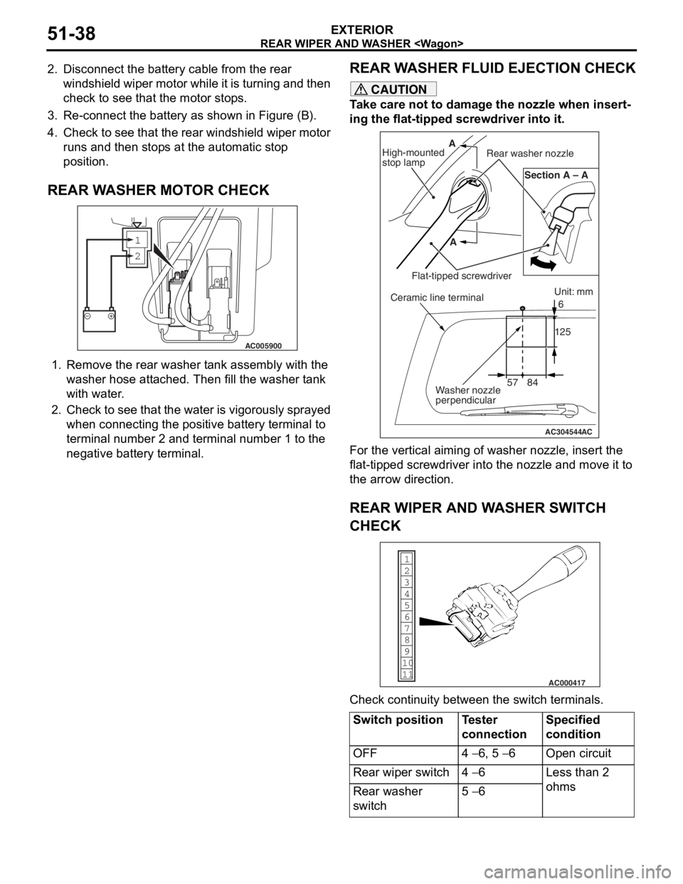
REAR WA SHER FLUI D EJECTION CHECK
CAUTION
Take care not to damage the nozzle when insert-
ing the flat-tipped screwdriver into it.
AC304544AC
Unit: mm
57 84 125
6
Section A – A
A
A
High-mounted
stop lamp Rear washer nozzle
Flat-tipped screwdriverCeramic line terminal
Washer nozzle
perpendicular
For the vertical aiming of washer nozzle, insert the
flat-tipped screwdriver into the nozzle and move it to
the arrow direction.
REAR WIPER AND WASHER SWITCH
CHECK
1
6
8
11 10 9 7
5 4
3
2
AC000417
Check continuity between the switch terminals.
Switch positionTester
connectionSpecified
condition
OFF4 − 6, 5 − 6Open circuit
Rear wiper switch4 − 6Less than 2
ohms
Rear washer
switch5 − 6