tow MITSUBISHI LANCER IX 2006 Service Manual
[x] Cancel search | Manufacturer: MITSUBISHI, Model Year: 2006, Model line: LANCER IX, Model: MITSUBISHI LANCER IX 2006Pages: 800, PDF Size: 45.03 MB
Page 35 of 800
ON-VEHICLE SERVICE
ENGINE COOLING14-21
ON-VEHICLE SERVICE
ENGINE COOLANT LEAK CHECKM1141001000300
WARNING
When pressure testing the cooling system,
slowly release cooling system pressure to
avoid getting burned by hot coolant.
CAUTION
•Be sure to completely clean away any mois-
ture from the places checked.
•When the tester is taken out, be careful not to
spill any coolant.
•
ACX01844
Cap adapter
Adapter
AC
Be careful when installing and removing the
tester and when testing not to deform the
filler neck of the radiator.
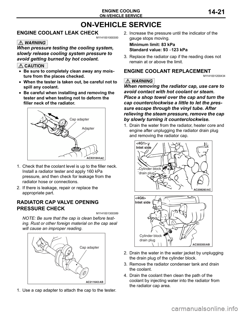
1. Check that the coolant leve l is up to the filler neck.
Install a radiator tester and apply 160 kPa
pressure, and then check for leakage from the
radiator hose or connections.
2. If there is leakage, repair or replace the
appropriate part.
RADIATOR CAP VALVE OPENING
PRESSURE CHECK
M1141001300389
NOTE: Be sure that the cap is clean before test-
ing. Rust or other foreign material on the cap seal
will cause an improper reading.
AC211643AB
Cap adapter
1. Use a cap adapter to attach the cap to the tester.
2. Increase the pressure until the indicator of the gauge stops moving.
Minimum limit: 83 kPa
Standard value: 93 − 123 kPa
3. Replace the radiator cap if the reading does not remain at or above the limit.
ENGINE COOLANT REPLACEMENT
M1141001200434
WARNING
When removing the radiator cap, use care to
avoid contact with hot coolant or steam.
Place a shop towel over the cap and turn the
cap counterclockwise a little to let the pres
-
sure escape through the vinyl tube. After
relieving the steam pres sure, remove the cap
by slowly turning it counterclockwise.
1. Drain the water from the radiator, heater core and
engine after unplugging the radiator drain plug
and removing the radiator cap.
AC208283AC
Cylinder block
drain plug
<4G1>
Inlet side
AC303355
<4G6>
Inlet side
Cylinder block
drain plug
AB
2. Drain the water in the water jacket by unplugging the drain plug of the cylinder block.
3. Remove the radiator condenser tank and drain
the coolant.
4. Drain the coolant then clean the path of the coolant by injecting water into the radiator from
the radiator cap area.
Page 55 of 800
INLET MANIFOLD
INTAKE AND EXHAUST15-5
INLET MANIFOLD
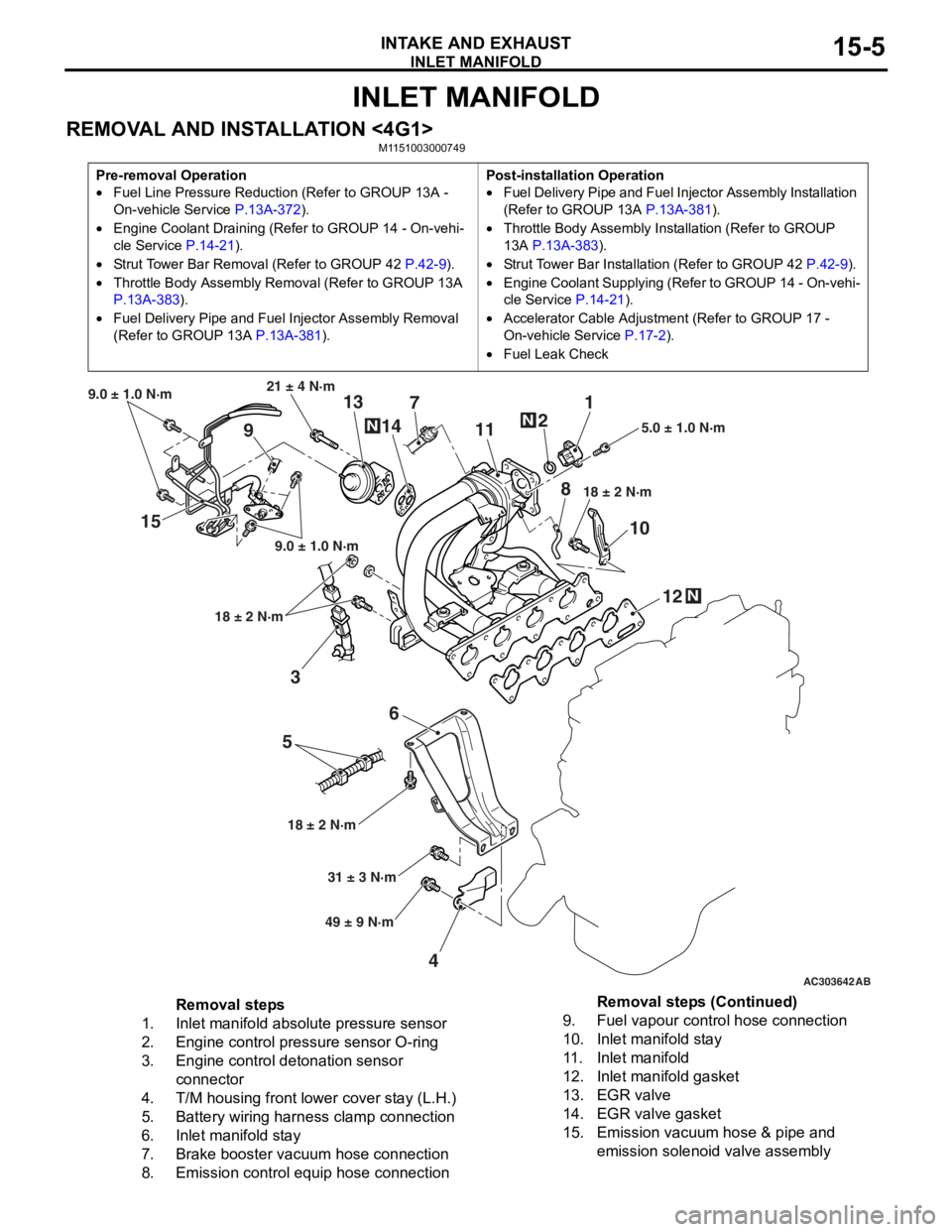
REMOVAL AND INSTALLATION <4G1>M1151003000749
Pre-removal Operation
•Fuel Line Pressure Reduction (Refer to GROUP 13A -
On-vehicle Service
P.13A-372).
•Engine Coolant Draining (Refer to GROUP 14 - On-vehi-
cle Service P.14-21).
•Strut Tower Bar Removal (Refer to GROUP 42 P.42-9).
•Throttle Body Assembly Re moval (Refer to GROUP 13A
P.13A-383).
•Fuel Delivery Pipe and Fuel Injector Assembly Removal
(Refer to GROUP 13A
P.13A-381).
Post-installation Operation
•Fuel Delivery Pipe and Fuel Injector Assembly Installation
(Refer to GROUP 13A
P.13A-381).
•Throttle Body Assembly Inst allation (Refer to GROUP
13A
P.13A-383).
•Strut Tower Bar Installati on (Refer to GROUP 42 P.42-9).
•Engine Coolant Supplying (Refer to GROUP 14 - On-vehi-
cle Service P.14-21).
•Accelerator Cable Adjustment (Refer to GROUP 17 -
On-vehicle Service
P.17-2).
•Fuel Leak Check
AC303642AB
15
36
5
4 12
10
7
1
2
11
9 13
14
21 ± 4 N·m
9.0 ± 1.0 N·m
9.0 ± 1.0 N·m
18 ± 2 N·m
18 ± 2 N·m 18 ± 2 N·m
5.0 ± 1.0 N·m
31 ± 3 N·m
49 ± 9 N·m
N
N
N
8
Removal steps
1.Inlet manifold absolute pressure sensor
2.Engine control pressure sensor O-ring
3.Engine control detonation sensor
connector
4.T/M housing front lower cover stay (L.H.)
5.Battery wiring harness clamp connection
6.Inlet manifold stay
7.Brake booster vacuum hose connection
8.Emission control equip hose connection
9.Fuel vapour control hose connection
10.Inlet manifold stay
11 .Inlet manifold
12.Inlet manifold gasket
13.EGR valve
14.EGR valve gasket
15.Emission vacuum hose & pipe and
emission solenoid valve assembly
Removal steps (Continued)
Page 56 of 800
INLET MANIFOLD
INTAKE AND EXHAUST15-6
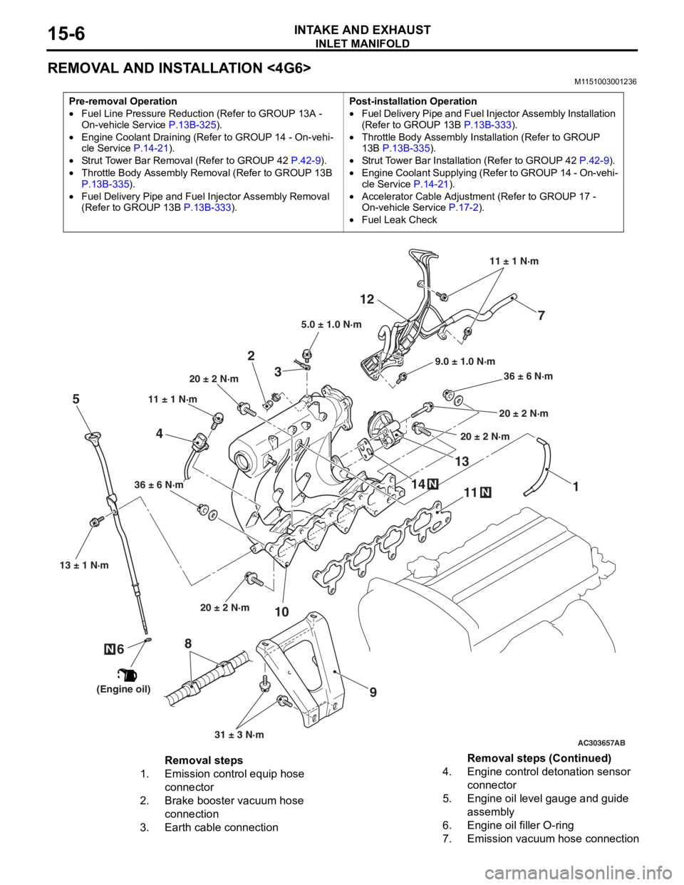
REMOVAL AND INSTALLATION <4G6>
M1151003001236
Pre-removal Operation
•Fuel Line Pressure Reduction (Refer to GROUP 13A -
On-vehicle Service P.13B-325).
•Engine Coolant Draining (Refer to GROUP 14 - On-vehi-cle Service P.14-21).
•Strut Tower Bar Removal (Refer to GROUP 42 P.42-9).
•Throttle Body Assembly Re moval (Refer to GROUP 13B
P.13B-335).
•Fuel Delivery Pipe and Fuel Injector Assembly Removal
(Refer to GROUP 13B
P.13B-333).
Post-installation Operation
•Fuel Delivery Pipe and Fuel Injector Assembly Installation
(Refer to GROUP 13B P.13B-333).
•Throttle Body Assembly Inst allation (Refer to GROUP
13B P.13B-335).
•Strut Tower Bar Installati on (Refer to GROUP 42 P.42-9).
•Engine Coolant Supplying (Refer to GROUP 14 - On-vehi-
cle Service P.14-21).
•Accelerator Cable Adjustment (Refer to GROUP 17 -
On-vehicle Service
P.17-2).
•Fuel Leak Check
AC303657
9.0 ± 1.0 N·m11 ± 1 N·m
20 ± 2 N·m 31 ± 3 N·m
36 ± 6 N·m
20 ± 2 N·m
20 ± 2 N·m
36 ± 6 N·m
20 ± 2 N·m
11
9
10
2
12
N14
13N
AB
5.0 ± 1.0 N·m
3
1
11 ± 1 N·m
4
N
13 ± 1 N·m
5
6
(Engine oil)
7
8
Removal steps
1.Emission control equip hose
connector
2.Brake booster vacuum hose
connection
3.Earth cable connection
4.Engine control detonation sensor
connector
5.Engine oil level gauge and guide
assembly
6.Engine oil filler O-ring
7.Emission vacuum hose connection
Removal steps (Continued)
Page 75 of 800
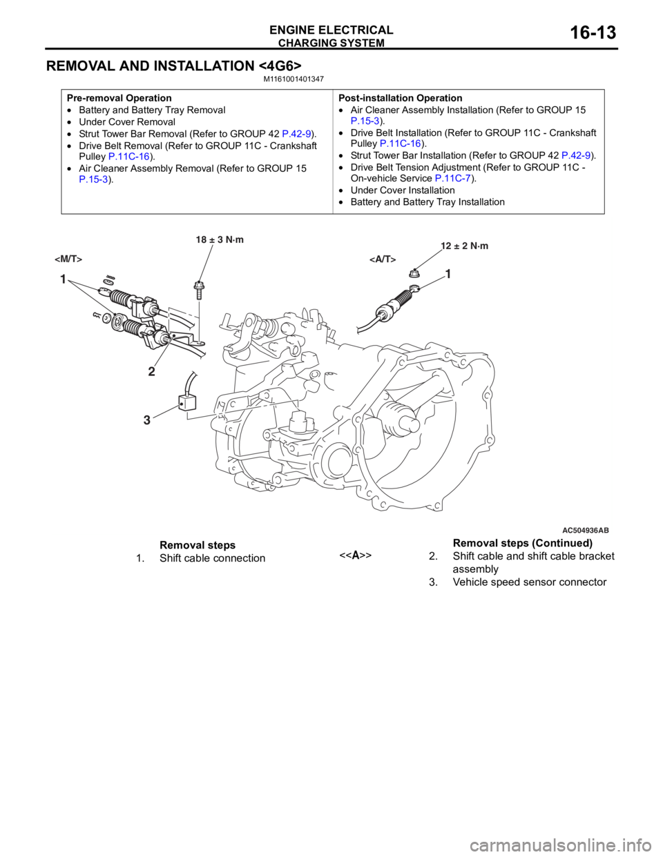
CHARGING SYSTEM
ENGINE ELECTRICAL16-13
REMOVAL AND INSTALLATION <4G6>
M1161001401347
Pre-removal Operation
•Battery and Battery Tray Removal
•Under Cover Removal
•Strut Tower Bar Removal (Refer to GROUP 42 P.42-9).
•Drive Belt Removal (Refer to GROUP 11C - Crankshaft
Pulley P.11C-16).
•Air Cleaner Assembly Remo val (Refer to GROUP 15 P.15-3).
Post-installation Operation
•Air Cleaner Assembly Installation (Refer to GROUP 15 P.15-3).
•Drive Belt Installation (Refer to GROUP 11C - Crankshaft
Pulley P.11C-16).
•Strut Tower Bar Installation (Refer to GROUP 42 P.42-9).
•Drive Belt Tension Adjustment (Refer to GROUP 11C -
On-vehicle Service
P.11C-7).
•Under Cover Installation
•Battery and Battery Tray Installation
AC504936
1 1
2
3
18 ± 3 N·m 12 ± 2 N·m
AB
Removal steps
1.Shift cable connection<>2.Shift cable and shift cable bracket
assembly
3.Vehicle speed sensor connector
Removal steps (Continued)
Page 89 of 800
STARTING SYSTEM
ENGINE ELECTRICAL16-27
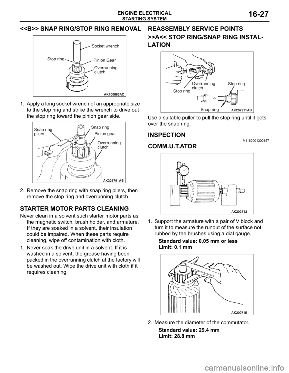
<> SNAP RING/STOP RING REMOVAL
AK100883AC
Socket wrench
Stop ring Pinion Gear
Overrunning
clutch
1. Ap ply a lo ng socket wr ench o f a n ap pro p ria t e size
to the stop ring and strike th e wrench to drive out
th e sto p ring toward th e pin i on g ear side.
AK202791
Snap ring
pliersSnap ring
Pinion gear
Overrunning
clutch
AB
2. Remove the snap ring with sna p ring pliers, th en
remove the stop ring an d overrunning clutch.
STARTER MOT O R P ARTS CLEANING
Never clean in a solvent such st arte r moto r p a rt s as
th e ma gnetic switch, brush hold e r , and arma ture.
If they are soake d in a solven t, their insulat i on
could be imp a ire d . When these p a rt s requ ire
clean ing, wipe of f co nt a m in ation with cloth .
1.Never so ak th e drive un it in a solve n t. If it is
washed in a solvent, th e grea se ha vin g been
p a cke d in th e over run n ing clutch at t he fa ct or y will
be washe d out. Wipe t he drive u n it with cloth if it
req u ires cleaning.
REASSEM BL Y SER V ICE POINT S
>>A<< STOP RING/SNAP RING INST AL-
LATION
AK202911
Overrunning
clutch Stop ring
Snap ring
Stop ring
AB
Use a suit
able puller to pull the stop ring u n til it ge t s
over t
he snap ring.
INSPECTION
M1162 0013 0015 7
COMM.U.T .A T O R
AK202712
1.Sup port the arma ture with a p a ir o f V block a nd
tu rn it t o mea s ure the run out of the surface not
ru bbed b y the brushes u s in g a dial g auge.
St andard va lue: 0.0 5 mm o r l ess
Limit: 0.1 mm
AK202715
2.Measure the diameter o f the commut ator .
St andard va lue: 29 .4 mm
Limit: 28.8 mm
Page 142 of 800
FRONT AXLE HUB ASSEMBLY
FRONT AXLE26-10
<
AC100128
MB990241
MB990767
AG
AC303949
MB990244
(Three)
MB990767
MB990242
MB991354
AF
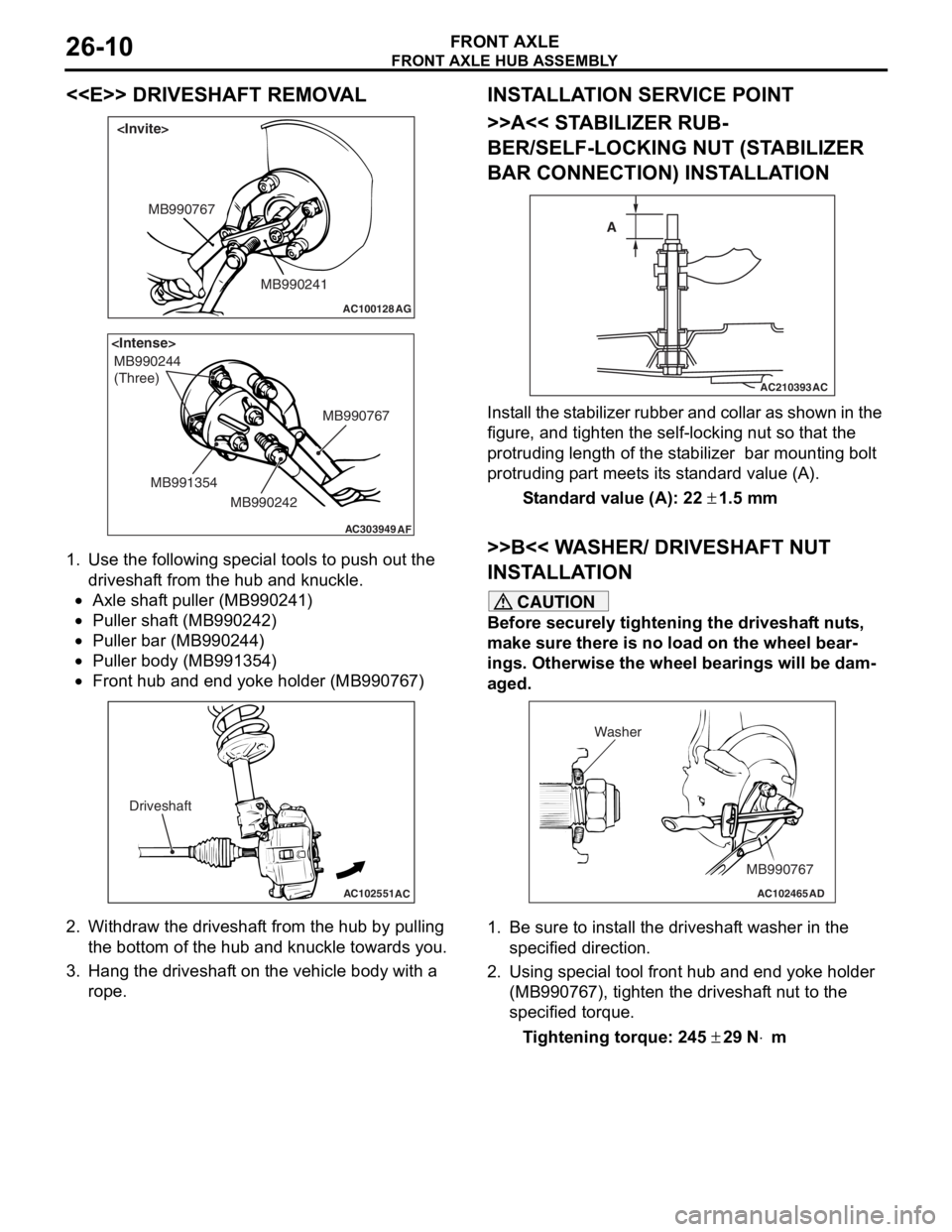
1.
Use the fo llo wing special to ols to pu sh ou t the
driveshaf t from the hub an d kn uckle.
•Axle shaf t puller (MB9 90241 )
•Puller shaft (MB990 242)
•Puller bar (MB990 244)
•Puller body (MB99135 4)
•
AC102551
AC
Driveshaft
Front hub a nd end yoke holder (MB99076 7)
2.Withdraw th e driveshaf t from the hu b by pulling
th e botto m of the hub and knuckle towards you .
3.Hang the dr ive s haf t on the vehicle b ody with a
rope.
INST ALLA T ION SER VICE POINT
>>A<< STABILIZER RUB-
BER/SELF-LOCKING NUT (ST A BILIZER
BAR CONNECTION) INST
ALLA TION
AC210393AC
A
I
n st a ll the st a b ili zer rubb er an d coll ar as sho w n in t he
figure
, and t i ghte n the self-locking nut so tha t the
protruding length
of the st abilize r bar mount ing b o lt
protruding p
a rt meet s it s st and ard value (A).
St andard va lue (A): 22 ± 1.5 m m
>>B<< W A SHER/ DRIVESHAFT NUT
INST
ALLA TION
CAUTION
Before securely tightening the driveshaft nuts,
make sure there is no load on the wheel bear
-
ings. Otherwise the wheel bearings will be dam-
aged.
AC102465AD
MB990767
Washer
1. Be sure to install the driveshaft washer in the
specified direction.
2. Using special tool front hub and end yoke holder (MB990767), tighten the driveshaft nut to the
specified torque.
Tightening torque: 245 ± 29 N⋅m
Page 148 of 800
AC102551AC
Drive shaft
DRIVESHAFT ASSEMBL Y
FRONT AXLE26-16
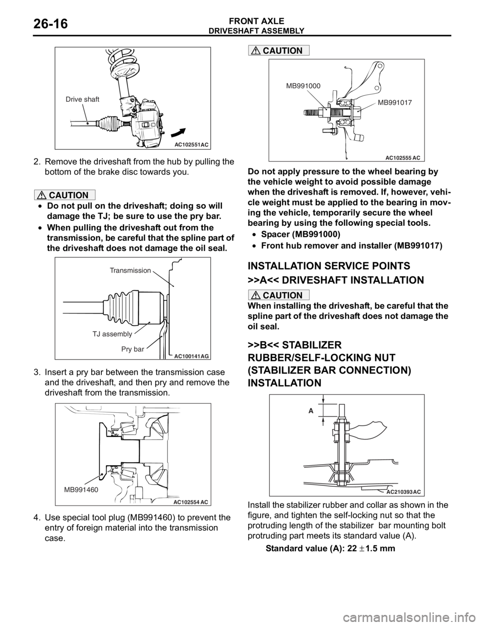
2.Remove th e dr ivesh a f t from th e h ub b y p u lling the
bo ttom of the brake disc toward s you.
CAUTION
•Do not pull on the driveshaft; doing so will
damage the TJ; be sure to use the pry bar.
•
AC100141
Transmission
TJ assembly Pry bar
AG
When pulling the driveshaft out from the
transmission, be careful that the spline part of
the driveshaft does not damage the oil seal.
3. Insert a pry bar between the transmission case and the driveshaft, and then pry and remove the
driveshaft from the transmission.
AC102554
MB991460
AC
4. Use special tool plug (MB991460) to prevent the
entry of foreign material into the transmission
case.
AC102555 AC
MB991017
MB991000
CAUTION
Do not apply pressure to the wheel bearing by
the vehicle weight to avoid possible damage
when the driveshaft is removed. If, however, vehi
-
cle weight must be applied to the bearing in mov-
ing the vehicle, temporarily secure the wheel
bearing by using the following special tools.
•Spacer (MB991000)
•Front hub remover and installer (MB991017)
INSTALLATION SERVICE POINTS
>>A<< DRIVESHAFT INSTALLATION
CAUTION
When installing the driveshaft, be careful that the
spline part of the driveshaft does not damage the
oil seal.
>>B<< STABILIZER
RUBBER/SELF-LOCKING NUT
(STABILIZER BAR CONNECTION)
INSTALLATION
AC210393
AC
A
Install the stabilizer rubber and collar as shown in the
figure, and tighten the self-locking nut so that the
protruding length of the stabilizer bar mounting bolt
protruding part meets its standard value (A).
Standard value (A): 22 ± 1.5 mm
Page 178 of 800
CROSSMEMBER
POWER PLANT MOUNT32-8
INSTALLATION SERVICE POINTS
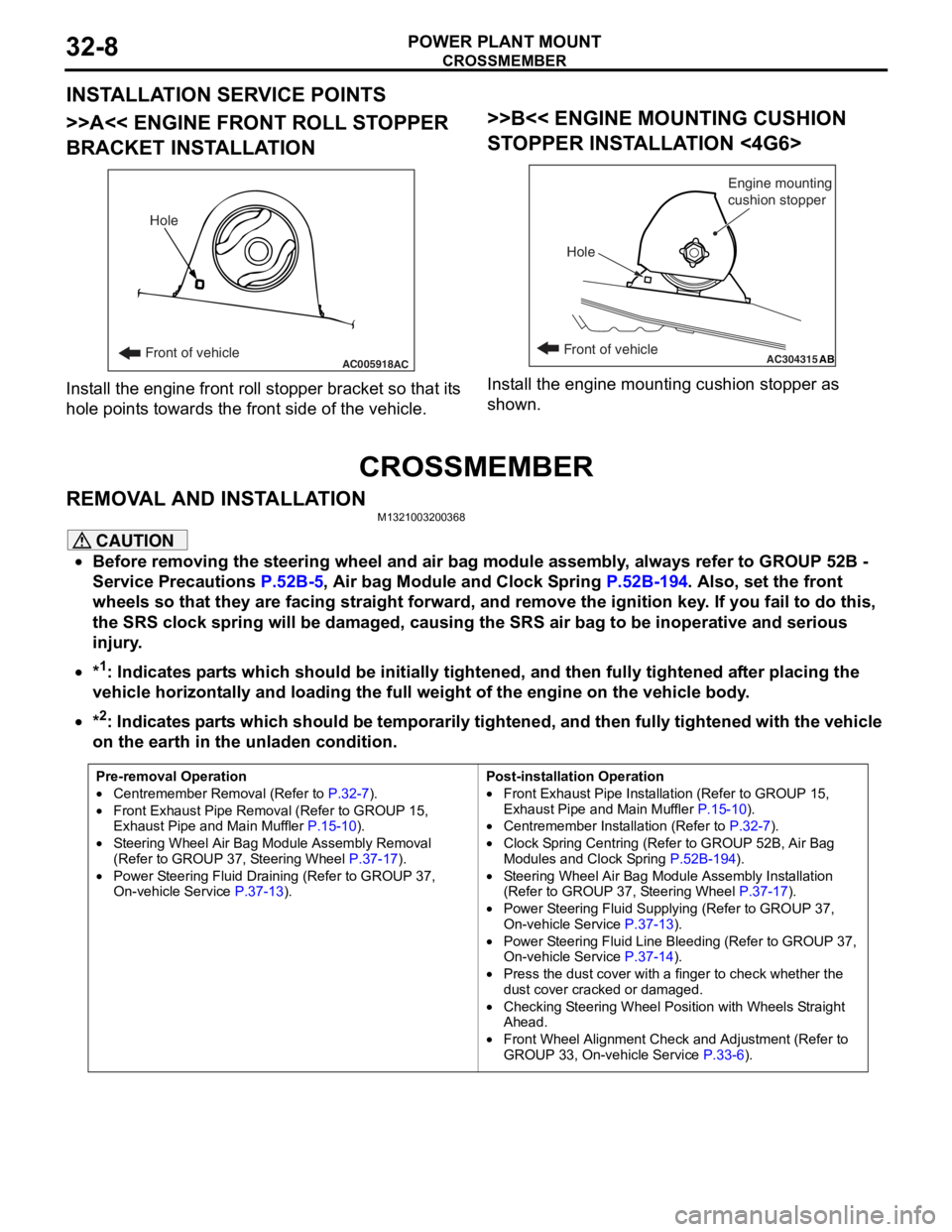
>>A<< ENGINE FRONT ROLL STOPPER
BRACKET INSTALLATION
AC005918Front of vehicleHoleAC
Inst
all th e en gine fron t roll stop per b r acket so that it s
hole
point s towards the fro n t side of the vehicle.
>>B<< ENGINE MOUNTING CUSHION
ST
OPPER INST ALLA TION <4G6>
AC304315ABFront of vehicle
Hole Engine mounting
cushion stopper
Inst
all the e ngin e mo untin g cushio n sto pper a s
shown.
CROSSMEMBER
REMOVA L AND INST ALLA TIONM13210032 0036 8
CAUTION
•Before removing the steering wheel and air bag module assembly, always refer to GROUP 52B -
Service Precautions
P.52B-5, Air bag Module and Clock Spring P.52B-194. Also, set the front
wheels so that they are facing straight forward, and remove the ignition key. If you fail to do this,
the SRS clock spring will be damaged, causing the SRS air bag to be inoperative and serious
injury.
•*1: Indicates parts which should be initially tightened, and then fully tightened after placing the
vehicle horizontally and loading the full weight of the engine on the vehicle body.
•
Pre-removal Operation
•Centremember Removal (Refer to P.32-7).
•Front Exhaust Pipe Remova l (Refer to GROUP 15,
Exhaust Pipe and Main Muffler P.15-10).
•Steering Wheel Air Bag Mo dule Assembly Removal
(Refer to GROUP 37, Steering Wheel P.37-17).
•Power Steering Fluid Draining (Refer to GROUP 37,
On-vehicle Service P.37-13).
Post-installation Operation
•Front Exhaust Pipe Installation (Refer to GROUP 15,
Exhaust Pipe and Main Muffler
P.15-10).
•Centremember Installation (Refer to P.32-7).
•Clock Spring Centring (Refer to GROUP 52B, Air Bag
Modules and Clock Spring P.52B-194).
•Steering Wheel Air Bag Module Assembly Installation
(Refer to GROUP 37, Steering Wheel P.37-17).
•Power Steering Fluid Supplying (Refer to GROUP 37,
On-vehicle Service P.37-13).
•Power Steering Fluid Line Bleeding (Refer to GROUP 37,
On-vehicle Service P.37-14).
•Press the dust cover with a finger to check whether the
dust cover cracked or damaged.
•Checking Steering Wheel Position with Wheels Straight
Ahead.
•Front Wheel Alignment Check and Adjustment (Refer to
GROUP 33, On-vehicle Service P.33-6).
*2: Indicates parts which should be temporarily tightened, and then fully tightened with the vehicle
on the earth in the unladen condition.
Page 188 of 800
ON-VEHICLE SERVICE
FRONT SUSPENSION33-6
ON-VEHICLE SERVICE
FRONT WHEEL ALIGNMENT CHECK AND
ADJUSTMENT
M1331000900886
Measure wheel alignment with alignment equipment
on a level surface. The front suspension, steering
system, wheels, and tyres should be serviced to nor
-
mal condition before measuring wheel alignment.
TOE-IN
Standard value:
At the centre of tyre tread: 1 ± 2 mm
Toe angle (per wheel): 0°03' ± 0°06'
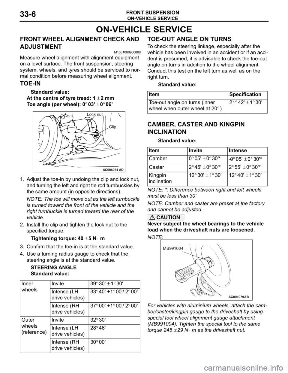
AC006074 AD
Lock nut
Clip
1.Adjust the to e-in by undoing th e clip and lock nut,
and turning th e lef t and rig h t tie rod turnbu ckles by
th e same amount (in op posite direct ions).
NOTE: The toe will move out as th e lef t turnbuckle
is turn
ed toward the fro n t of th e ve hicle an d the
right tu
rnbuckle is turned t o ward the rear of the
vehicle.
2. In st all the clip and tighten the lock nut to the
specifie d torqu e .
Ti ghte n ing torque: 40 ± 5 N⋅m
3.Conf irm t hat the toe-in is at the st anda rd value.
4.Use a turn ing ra dius gaug e to check tha t the
steering ang le is at the st an dard value .
STEE R I N G AN G L E
St andard va lue:
Inner
wheelsInvite39°30' ± 1°30'
Intense (LH
drive vehicles)33°40' +1°00'/−2°00'
Intense (RH
drive vehicles)37°00' +1°00'/−2°00'
Outer
wheels
(reference)Invite32°30'
Intense (LH
drive vehicles)28°46'
Intense (RH
drive vehicles)30°00'
TO E-OUT ANGLE ON TURNS
To check the stee ring linkage, e s pe cially af ter the
vehicle has been invo
lve d in an accid ent or if an a cci
-
dent is pres umed, it is advisab le to check th e toe-ou t
angle
on tu rns in addition to the wh eel a lig nmen t.
Conduct this test on th e lef t tu rn as we ll a s on the
right turn.
St andard va lue:
ItemSpecification
Toe-out angle on turns (inner
wheel when outer wheel at 20
°)
21°42' ± 1°30'
CAMBER, CASTER AND KINGPIN
INCLINA
T ION
St andard va lue:
ItemInviteIntense
Camber0°05' ± 0°30'*−0°05' ± 0°30'*
Caster2°45' ± 0°30'*2°55' ± 0°30'*
Kingpin
inclination12°30' ± 1°30'12°40' ± 1°30'
NOTE: *: Diffe rence between right and lef t wheels
must be less than 30'
NOTE: Camber and caster are prese t at th e factory
and cannot be adjust ed.
CAUTION
Never subject the wheel bearings to the vehicle
load when the driveshaft nuts are loosened.
NOTE:
AC001079
MB991004
AB
For vehicles with aluminium wheels, attach the cam-
ber/caster/kingpin gauge to the driveshaft by using
special tool wheel alignment gauge attachment
(MB991004). Tighten the special tool to the same
torque 245
± 29 N⋅m as the driveshaft nut.
Page 211 of 800
