washer fluid MITSUBISHI LANCER IX 2006 Service Manual
[x] Cancel search | Manufacturer: MITSUBISHI, Model Year: 2006, Model line: LANCER IX, Model: MITSUBISHI LANCER IX 2006Pages: 800, PDF Size: 45.03 MB
Page 146 of 800

DRIVESHAFT ASSEMBLY
FRONT AXLE26-14
DRIVESHAFT ASSEMBLY
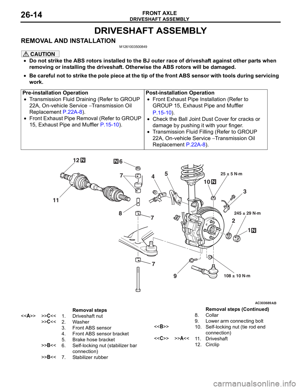
REMOVAL AND INSTALLATIONM1261003500849
CAUTION
•Do not strike the ABS rotors installed to the BJ outer race of driveshaft against other parts when
removing or installing the driveshaft. Otherwise the ABS rotors will be damaged.
•
Pre-installation Operation
•Transmission Fluid Draining (Refer to GROUP
22A, On-vehicle Service
− Transmission Oil
Replacement
P.22A-8).
•Front Exhaust Pipe Removal (Refer to GROUP
15, Exhaust Pipe and Muffler
P.15-10).
Post-installation Operation
•Front Exhaust Pipe Installation (Refer to
GROUP 15, Exhaust Pipe and Muffler
P.15-10).
•Check the Ball Joint Dust Cover for cracks or
damage by pushing it with your finger.
•Transmission Fluid Filling (Refer to GROUP
22A, On-vehicle Service
− Transmission Oil
Replacement
P.22A-8).
AC303689AB
9
N
N
NN
10
7
4
3
2 1
25 ± 5 N·m
245 ± 29 N·m
108 ± 10 N·m
8
5
6
11 12
77
Removal steps
<>>>C<<1.Driveshaft nut
>>C<<2.Washer
3.Front ABS sensor
4.Front ABS sensor bracket
5.Brake hose bracket
>>B<<6.Self-locking nut (stabilizer bar
connection)
>>B<<7.Stabilizer rubber
8.Collar
9.Lower arm connecting bolt
<>10.Self-locking nut (tie rod end
connection)
<
12.Circlip
Be careful not to strike the pole piece at the tip of the front ABS sensor with tools during servicing
work.
Removal steps (Continued)
Page 365 of 800

WINDSHIELD WIPER AND WASHER
EXTERIOR51-33
INSPECTION
M1511007700313
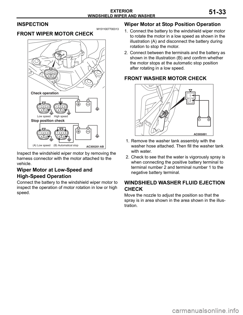
FRONT WIPER MOTOR CHECK
14 23
5
14 23
514 23
5
14 23
5
AC305201
14 23
5
Check operation
Low speed High speed
(A) Low speed (B) Automatical stop
Stop position check
AB
Inspe c t th e windshie l d wipe r mot o r by removing the
harness connector wit
h the motor a t t a ched to the
vehicle
.
Wiper Motor at Low-S peed and
High-S
peed Operation
Connect the ba ttery to the windsh i eld wiper motor to
insp
ect the ope ration of motor rot a tion in low or high
spee
d.
Wiper Motor at S t op Position Operation
1.Conn ect t he batt e ry to the wind shield wip e r mot o r
to rot a te th e motor in a low sp eed a s shown in the
illu stration (A) an d disco nnect the ba ttery durin g
ro t a tion to stop the motor .
2.Co nn ect b e t w ee n t h e te rmin als an d the b a tt ery as
shown in the illu strat i on (B) a nd co nfirm whether
th e mo tor sto p s at th e auto m atic stop po sition
a f ter rot a ting in a low sp eed.
FRONT WA SHER MOT O R CHECK
1
2
AC005891
1.Remove t he wash er t ank assembly wit h the
washer hose att a ched. T hen fill t he wash er t ank
with wa ter .
2.Check to see that th e wa ter is vigo rously sp ray is
when conn ecting the positive batt e ry te rmin al to
termina l number 2 and te rmin al nu mber 1 to th e
neg ative batt e ry te rmin al.
WI NDSHIELD W A SHER FLUID EJECTION
CHECK
Move the nozzle to adjust th e position so that th e
spray is in a
r ea shown in the are a sh own in t he illus
-
tration.
Page 371 of 800

HEADLAMP WASHER
EXTERIOR51-39
HEADLAMP WASHER
TROUBLESHOOTINGM1511000700356
The headlamp washer is controlled by the Smart Wir-
ing System (SWS). For troubleshooting, refer to
GROUP 54B, Troubleshooting
P.54B-15 or GROUP
54C, Troubleshooting P.54C-4.
HEADLAMP WASHER
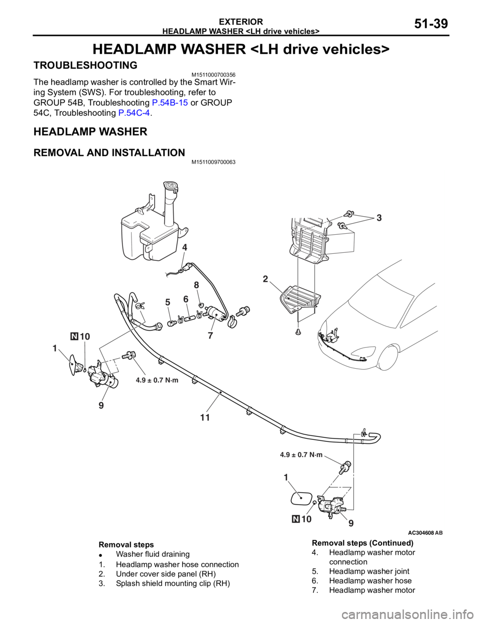
REMOVAL AND INSTALLATION
M1511009700063
AC304608AB
10N
2
4
56
8
7
1
9
11
9
1
10N
4.9 ± 0.7 N·m
4.9 ± 0.7 N·m
3
Removal steps
•Washer fluid draining
1.Headlamp washer hose connection
2.Under cover side panel (RH)
3.Splash shield mounting clip (RH)
4.Headlamp washer motor
connection
5.Headlamp washer joint
6.Headlamp washer hose
7.Headlamp washer motor
Removal steps (Continued)