wheel bolt torque MITSUBISHI LANCER IX 2006 Service Manual
[x] Cancel search | Manufacturer: MITSUBISHI, Model Year: 2006, Model line: LANCER IX, Model: MITSUBISHI LANCER IX 2006Pages: 800, PDF Size: 45.03 MB
Page 135 of 800
SERVICE SPECIFICATIONS
FRONT AXLE26-3
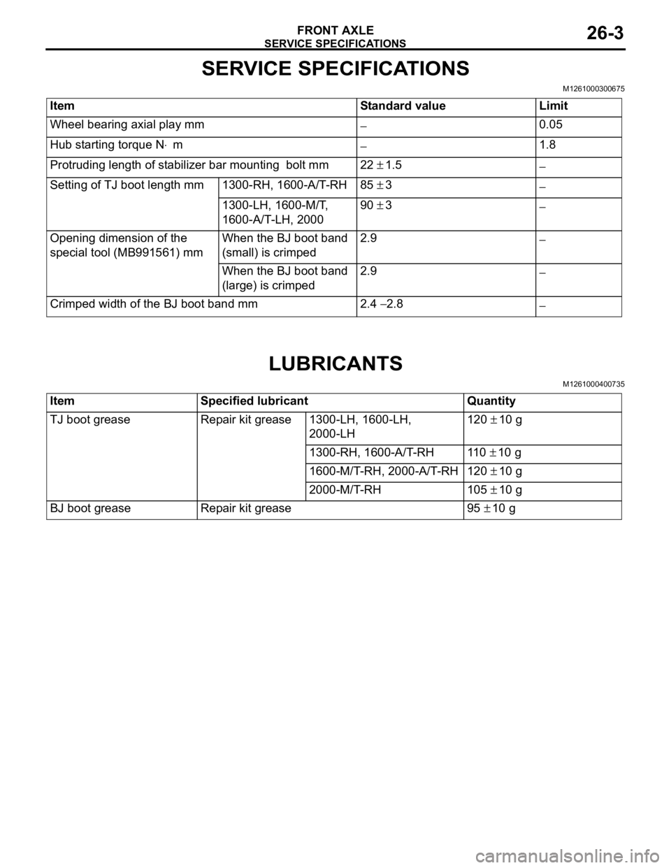
SERVICE SPECIFICATIONS
M1261000300675
ItemStandard valueLimit
Wheel bearing axial play mm−0.05
Hub starting torque N⋅m−1.8
Protruding length of stabilizer bar mounting bolt mm22 ± 1.5−
Setting of TJ boot length mm1300-RH, 1600-A/T-RH85 ± 3−
1300-LH, 1600-M/T,
1600-A/T-LH, 200090 ± 3−
Opening dimension of the
special tool (MB991561) mmWhen the BJ boot band
(small) is crimped2.9−
When the BJ boot band
(large) is crimped2.9 −
Crimped width of the BJ boot band mm2.4 − 2.8−
LUBRICANTS
M1261000400735
ItemSpecified lubricantQuantity
TJ boot greaseRepair kit grease1300-LH, 1600-LH,
2000-LH120 ± 10 g
1300-RH, 1600-A/T-RH11 0 ± 10 g
1600-M/T-RH, 2000-A/T-RH120 ± 10 g
2000-M/T-RH105 ± 10 g
BJ boot greaseRepair kit grease95 ± 10 g
Page 143 of 800
FRONT AXLE HUB ASSEMBLY
FRONT AXLE26-11
INSPECTION
M1261001800242
•Check the hub for cracks and spline for wear.
•Check the knuckle for cracks.
•Check for defective bearing.
NOTE: If the meshing of the wheel bearing outer
race and the knuckle, or of the wheel bearing
inner race and the hub, is loose, replace the
bearing or damaged parts.
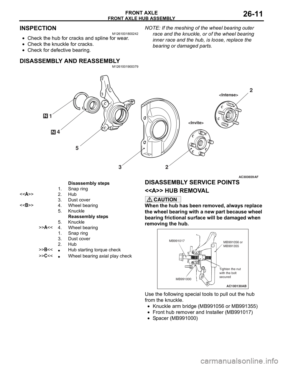
DISASSEMBLY AND REASSEMBLY
M1261001900379
AC303659
N
N4
1
5 3 2
AF
2
Disassembly steps
1.Snap ring
<>2.Hub
3.Dust cover
<>4.Wheel bearing
5.Knuckle
Reassembly steps
5.Knuckle
>>A<<4.Wheel bearing
1.Snap ring
3.Dust cover
2.Hub
>>B<<•Hub starting torque check
>>C<<•Wheel bearing axial play check
DISASSEMBL
Y SER V ICE POINTS
< > HUB REMOV A L
CAUTION
When the hub has been removed, always replace
the wheel bearing with a new part because wheel
bearing frictional surface will be damaged when
removing the hub.
AC100130
Tighten the nut
with the bolt
secured MB991056 or
MB991355
MB991017
MB991000 AB
Use the following special tools to pull out the hub
from the knuckle.
•Knuckle arm bridge (MB991056 or MB991355)
•Front hub remover and Installer (MB991017)
•Spacer (MB991000)
Page 144 of 800
FRONT AXLE HUB ASSEMBLY
FRONT AXLE26-12
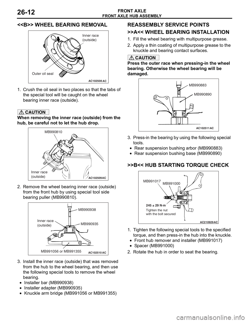
<> WHEEL BEARING REMOVAL
AC102508AC
Inner race
(outside)
Outer oil seal
1. Crush th e oil seal in two pl ace s so t hat t he t abs of
th e spe c ia l too l will be caugh t on th e wheel
be aring inne r race (out side).
CAUTION
When removing the inner race (outside) from the
hub, be careful not to let the hub drop.
AC102509
MB990810
Inner race
(outside)
AC
2. Remove the wheel bearing inner race (outside) from the front hub by using special tool side
bearing puller (MB990810).
AC102510 AC
MB990938
MB990935
MB991056 or MB991355
Inner race
(outside)
3. Install the inner race (outside) that was removed
from the hub to the wheel bearing, and then use
the following special tools to remove the wheel
bearing.
•Installer bar (MB990938)
•Installer adapter (MB990935)
•Knuckle arm bridge (MB991056 or MB991355)
REASSEMBLY SERVICE POINTS
>>A<< WHEEL BEARING INSTALLATION
1. Fill the wheel bearing with multipurpose grease.
2. Apply a thin coating of multipurpose grease to the knuckle and bearing contact surfaces.
CAUTION
Press the outer race when pressing-in the wheel
bearing. Otherwise the wheel bearing will be
damaged.
AC102511
MB990883
MB990890
AC
3. Press-in the bearing by using the following special tools.
•Rear suspension bushing arbor (MB990883)
•Rear suspension bushing base (MB990890)
>>B<< HUB STARTING TORQUE CHECK
AC210929AC
MB991000
MB991017
245 ± 29 N·m
Tighten the nut
with the bolt secured
1. Tighten the following special tools to the specified torque, and then press-in the hub into the knuckle.
•Front hub remover and installer (MB991017)
•Spacer (MB991000)
2. Rotate the hub in order to seat the bearing.
Page 145 of 800
AC100136
MB990685MB990326
AB
FRONT AXLE HUB ASSEMBL Y
FRONT AXLE26-13
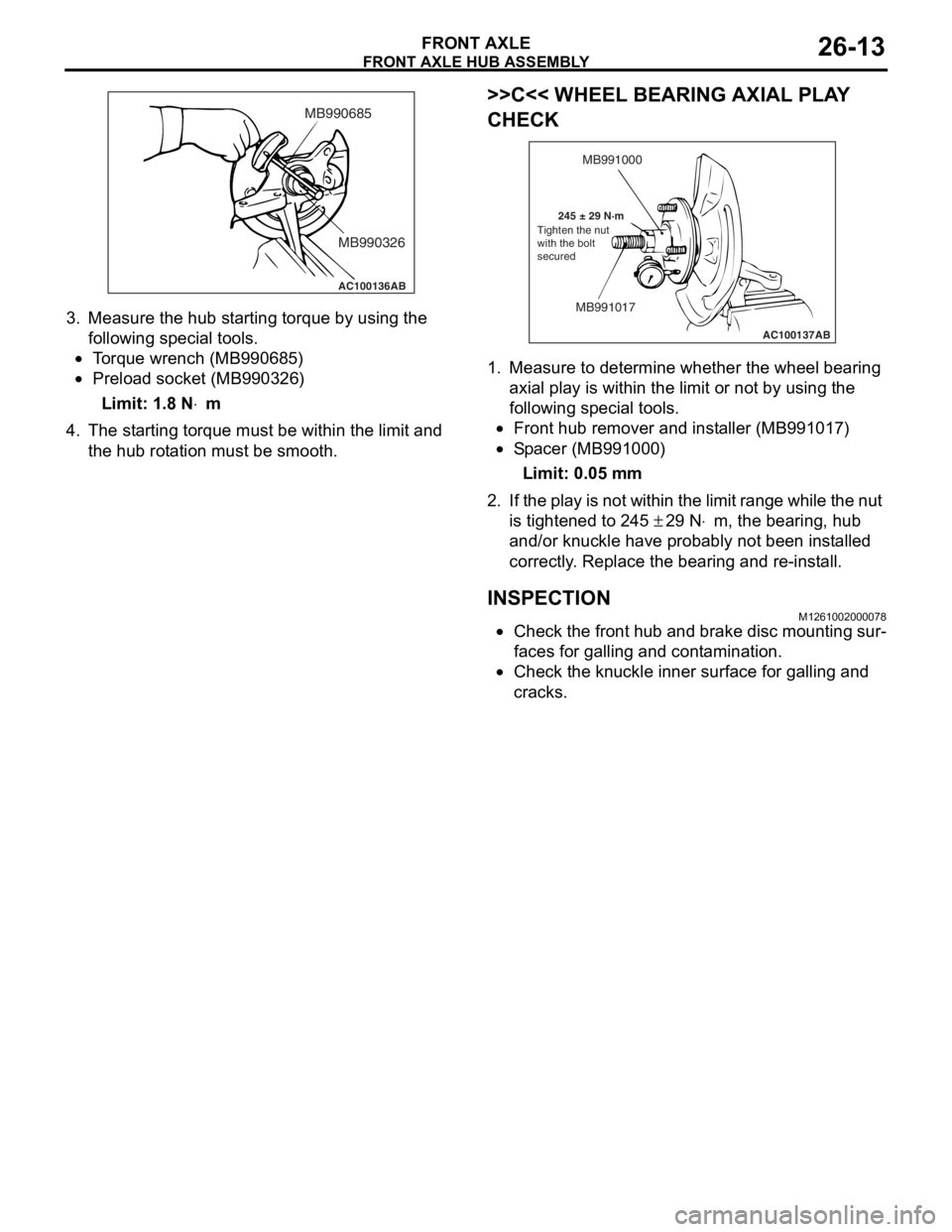
3.Measure the hub st a r ting torque b y using the
fo llowing special to ols.
•To rque wren ch (MB99068 5)
•Preload socket (MB9 90326 )
Limit: 1.8 N⋅m
4.Th e st arting torq ue must b e within the limit an d
th e hub rot a tion must be smoo th.
>>C<< WH EEL BEARING AXIAL PLA Y
CHECK
AC100137
MB991000
MB991017
245 ± 29 N·m AB
Tighten the nut
with the bolt
secured
1.
Measure to d e termine whe t her th e wheel bearing
a x ial pla y is with in the limit o r not by using t he
fo llowing special to ols.
•Front hub re mover and inst a ller (MB9910 17)
•Sp a c er (MB9910 00)
Limit: 0.05 mm
2. If the play is not wit h in the limit rang e while the nut
is tighten ed to 2 45
± 29 N⋅m, the bearing, hu b
a
nd/or knuckle
have
proba
bly not be en in st alled
correctly
. Replace
the be
aring and re -inst a ll.
INSPECTION
M12610020 0007 8
•Check the fro n t hu b and brake disc mo untin g sur-
faces for gallin g and cont amination.
•Check the knu c kle in ner surface for ga lling an d
crac
ks .
Page 160 of 800
ON-VEHICLE SERVICE
REAR AXLE27-4
ON-VEHICLE SERVICE
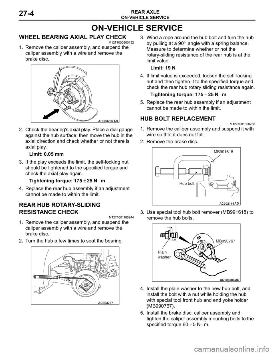
WHEEL BEARING AXIAL PLAY CHECKM1271000900452
1. Remove the caliper assembly, and suspend the caliper assembly with a wire and remove the
brake disc.
AC303736AB
2.Check the be aring ' s axial play . Place a dial gau ge
ag ainst th e hub su rface; then mo ve t he hu b in the
axial dire ction and check whe t her or not the r e is
axial pla y .
Limit: 0.05 mm
3.If the play e xce eds the limit, the self -lockin g nut
should be tighte ned to the specified torque and
check the axial play again .
Ti ghte n ing torque: 175 ± 25 N⋅m
4.Replace the re ar hub a s sembly if an ad justmen t
cannot be made to within the limit.
REAR HUB ROTA R Y -SLIDING
RESIST
ANCE CHECK
M127100 1 1 0024 4
1.Remove the caliper assembly , a nd suspe nd the
caliper assembly with a wire an d remove t he
bra k e d i sc.
2.T u rn the hu b a few times to seat th e bea ring.
AC303737
3.Wind a rope a r ound the hu b bolt and turn t he hub
b y pullin g at a 90
° angle with a spring balance.
Measure to d
e
termine whe t her or not the
ro
t
a
ry-sliding resist an ce of the rea r hub is at the
limit va
lue.
Limit: 19 N
4.If limit value is exceeded , loo s en the self-locking
n u t and then tighten it to the specified torque and
check the rear hu b rot a ry sliding resist ance again.
Ti ghte n ing torque: 175 ± 25 N⋅m
5.Replace the re ar hub assembly if an a d justmen t
canno t be made to within the limit.
HUB BOLT REPLACEMENTM12710010 0025 8
1.Remove the calip er assembly and suspe nd it with
wire so t hat it does not fa ll.
2.Remove the bra k e d i sc.
AC302114
MB991618
AD
Hub bolt
3.Use spe c ia l too l hub bolt remover (MB99161 8) to
re move the h ub bo lt s.
AC104588
MB990767
Plain
washer
AC
4. In st all the plain wa sher to the n e w hub b o lt, a nd
inst all the bolt with a nu t while hold i ng the hub
wit h spe c ia l too l fron t hub a nd end yoke holder
(MB99076 7).
5.In st all the bra k e d i sc, ca lip er assembly and
tighten th e caliper assembly mount ing bolt s to the
specifie d torqu e 60
± 5 N⋅m.
Page 201 of 800
SERVICE SPECIFICATIONS
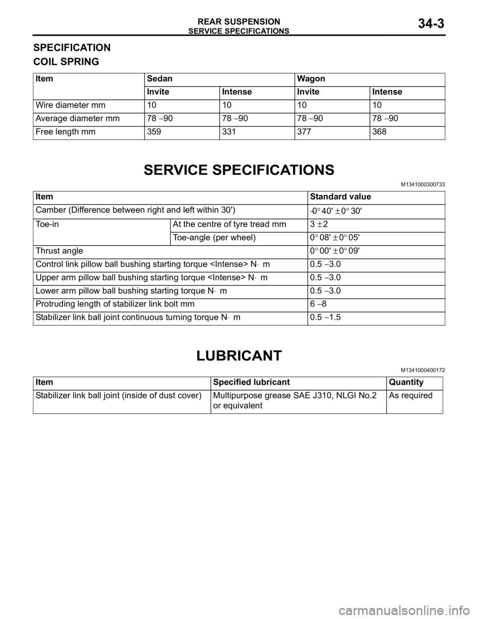
REAR SUSPENSION34-3
SPECIFICATION
COIL SPRING
ItemSedanWagon
InviteIntenseInviteIntense
Wire diameter mm10101010
Average diameter mm78 − 9078 − 9078 − 9078 − 90
Free length mm359331377368
SERVICE SPECIFICATIONS
M1341000300733
ItemStandard value
Camber (Difference between right and left within 30') −0°40' ± 0°30'
Toe-inAt the centre of tyre tread mm3 ± 2
Toe-angle (per wheel)0°08' ± 0°05'
Thrust angle0°00' ± 0°09'
Control link pillow ball bushing starting torque
Upper arm pillow ball bushing starting torque
Lower arm pillow ball bushing starting torque N⋅m0.5 − 3.0
Protruding length of stabilizer link bolt mm6 − 8
Stabilizer link ball joint continuous turning torque N⋅m0.5 − 1.5
LUBRICANT
M1341000400172
ItemSpecified lubricantQuantity
Stabilizer link ball joint (inside of dust cover)Multipurpose grease SAE J310, NLGI No.2
or equivalentAs required
Page 204 of 800
ON-VEHICLE SERVICE
REAR SUSPENSION34-6
ON-VEHICLE SERVICE
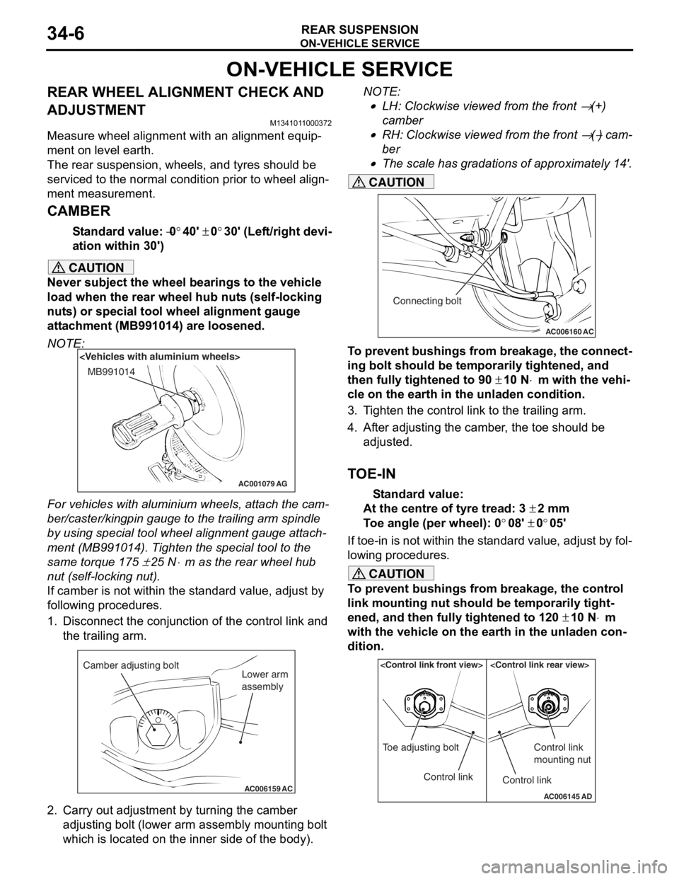
REAR WHEEL ALIGNMENT CHECK AND
ADJUSTMENT
M1341011000372
Measure wheel alignment with an alignment equip-
ment on level earth.
The rear suspension, wheels, and tyres should be
serviced to the normal condition prior to wheel align
-
ment measurement.
CAMBER
Standard value: −0°40' ± 0°30' (Left/right devi-
ation within 30')
CAUTION
Never subject the wheel bearings to the vehicle
load when the rear wheel hub nuts (self-locking
nuts) or special tool wheel alignment gauge
attachment (MB991014) are loosened.
NOTE:
AC001079
MB991014
AG
For vehicles with aluminium wheels, attach the cam-
ber/caster/kingpin gauge to the trailing arm spindle
by using special tool wheel alignment gauge attach
-
ment (MB991014). Tighten the special tool to the
same torque 175
± 25 N⋅m as the rear wheel hub
nut (self-locking nut).
If camber is not within the standard value, adjust by
following procedures.
1. Disconnect the conjunction of the control link and the trailing arm.
AC006159 AC
Camber adjusting bolt
Lower arm
assembly
2. Carry out adjustment by turning the camber
adjusting bolt (lower arm assembly mounting bolt
which is located on the inner side of the body).
NOTE: .
•LH: Clockwise viewed from the front → (+)
camber
•RH: Clockwise viewed from the front → (−) cam-
ber
•
AC006160 AC
Connecting bolt
The scale has gradations of approximately 14'.
CAUTION
To prevent bushings from breakage, the connect-
ing bolt should be temporarily tightened, and
then fully tightened to 90
± 10 N⋅m with the vehi-
cle on the earth in the unladen condition.
3. Tighten the control link to the trailing arm.
4. After adjusting the camber, the toe should be
adjusted.
TOE-IN
Standard value:
At the centre of tyre tread: 3 ± 2 mm
Toe angle (per wheel): 0°08' ± 0°05'
If toe-in is not within the standard value, adjust by fol-
lowing procedures.
CAUTION
To prevent bushings from breakage, the control
link mounting nut should be temporarily tight
-
ened, and then fully tightened to 120 ± 10 N⋅m
with the vehicle on the earth in the unladen con
-
dition.
AC006145 AD
Control link
Toe adjusting boltControl link
Control link
mounting nut
Page 242 of 800
ON-VEHICLE SERVICE
POWER STEERING37-12
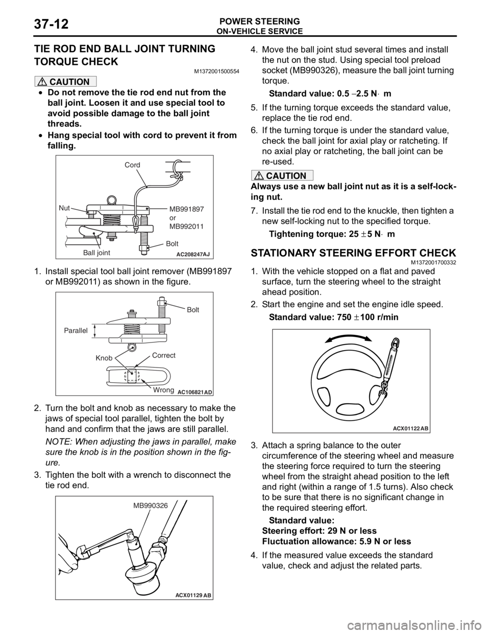
TIE ROD END BALL JOINT TURNING
TORQUE CHECK
M1372001500554
CAUTION
•Do not remove the tie rod end nut from the
ball joint. Loosen it and use special tool to
avoid possible damage to the ball joint
threads.
•
AC208247AJ
CordBoltMB991897
or
MB992011
Nut
Ball joint
Hang special tool with cord to prevent it from
falling.
1. Install special tool ball joint remover (MB991897 or MB992011) as shown in the figure.
AC106821
Knob
Parallel
Bolt
Correct Wrong
AD
2. Turn the bolt and knob as necessary to make the jaws of special tool parallel, tighten the bolt by
hand and confirm that the jaws are still parallel.
NOTE: When adjusting the jaws in parallel, make
sure the knob is in the position shown in the fig
-
ure.
3. Tighten the bolt with a wrench to disconnect the tie rod end.
ACX01129 AB
MB990326
4. Move the ball joint stud several times and install
the nut on the stud. Using special tool preload
socket (MB990326), measure the ball joint turning
torque.
Standard value: 0.5 − 2.5 N⋅m
5. If the turning torque exceeds the standard value, replace the tie rod end.
6. If the turning torque is under the standard value, check the ball joint for axial play or ratcheting. If
no axial play or ratcheting, the ball joint can be
re-used.
CAUTION
Always use a new ball joint nut as it is a self-lock-
ing nut.
7. Install the tie rod end to the knuckle, then tighten a new self-locking nut to the specified torque.
Tightening torque: 25 ± 5 N⋅m
STATIONARY STEERING EFFORT CHECKM1372001700332
1. With the vehicle stopped on a flat and paved
surface, turn the steering wheel to the straight
ahead position.
2. Start the engine and set the engine idle speed.
Standard value: 750 ± 100 r/min
ACX01122 AB
3. Attach a spring balance to the outer
circumference of the steering wheel and measure
the steering force required to turn the steering
wheel from the straight ahead position to the left
and right (within a range of 1.5 turns). Also check
to be sure that there is no significant change in
the required steering effort.
Standard value:
Steering effort: 29 N or less
Fluctuation allowance: 5.9 N or less
4. If the measured value exceeds the standard value, check and adjust the related parts.