width MITSUBISHI LANCER IX 2006 Service Manual
[x] Cancel search | Manufacturer: MITSUBISHI, Model Year: 2006, Model line: LANCER IX, Model: MITSUBISHI LANCER IX 2006Pages: 800, PDF Size: 45.03 MB
Page 135 of 800

SERVICE SPECIFICATIONS
FRONT AXLE26-3
SERVICE SPECIFICATIONS
M1261000300675
ItemStandard valueLimit
Wheel bearing axial play mm−0.05
Hub starting torque N⋅m−1.8
Protruding length of stabilizer bar mounting bolt mm22 ± 1.5−
Setting of TJ boot length mm1300-RH, 1600-A/T-RH85 ± 3−
1300-LH, 1600-M/T,
1600-A/T-LH, 200090 ± 3−
Opening dimension of the
special tool (MB991561) mmWhen the BJ boot band
(small) is crimped2.9−
When the BJ boot band
(large) is crimped2.9 −
Crimped width of the BJ boot band mm2.4 − 2.8−
LUBRICANTS
M1261000400735
ItemSpecified lubricantQuantity
TJ boot greaseRepair kit grease1300-LH, 1600-LH,
2000-LH120 ± 10 g
1300-RH, 1600-A/T-RH11 0 ± 10 g
1600-M/T-RH, 2000-A/T-RH120 ± 10 g
2000-M/T-RH105 ± 10 g
BJ boot greaseRepair kit grease95 ± 10 g
Page 236 of 800

SERVICE SPECIFICATIONS
POWER STEERING37-6
SERVICE SPECIFICATIONS
M1372000300795
ItemStandard valueLimit
Steering wheel free
play mmWith engine running−30
With engine stopped10 or less−
Steering angleInner wheelInvite39°30' ± 1°30'−
Intense (LH drive vehicles)33°40' +1°00'/-2°00'−
Intense (RH drive vehicles)37°00' +1°00'/-2°00'−
Outer wheel
(reference)Invite32°30'−
Intense (LH drive vehicles)28°46'−
Intense (RH drive vehicles)30°00'−
Toe-inAt the centre of tyre tread mm1 ± 2−
Toe-angle (per wheel)0°03' ± 06'−
Tie rod end ball joint turning torque N⋅m0.5 − 2.5−
Tie rod swing resistance N [Tie rod swing torque N⋅m]8 − 27 [1.5 − 4.9]−
Stationary steering effort N [Fluctuation allowance N]29 or less [5.9 or less]−
Oil pump pressure
MPa (750
± 100 r/min.)
Oil pump relief pressure8.8 − 9.5−
Pressure under no-load conditions0.2 − 0.7−
Steering gear retention hydraulic pressure8.8 − 9.5−
Oil pressure switch operating pressure
MPaOFF → ON1.5 − 2.0−
ON → OFF0.7 − 2.0−
Steering gear total pinion torque N⋅m
[Change in torque N
⋅m]
Invite0.8 − 2.1 [0.6 or less]−
Intense0.7 − 2.1 [0.6 or less]−
Opening dimension of special tool boot band crimping tool (MB991561)
mm2.9−
Band crimped width mm2.4 − 2.8−
Page 264 of 800
POWER STEERING GEAR BOX AND LINKAGE
POWER STEERING37-34
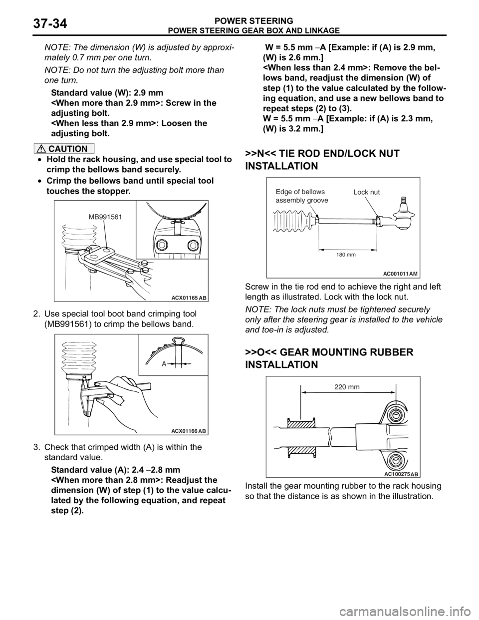
NOTE: The dimension (W) is adjusted by approxi-
mately 0.7 mm per one turn.
NOTE: Do not turn the adjusting bolt more than
one turn.
Standard value (W): 2.9 mm
adjusting bolt.
adjusting bolt.
CAUTION
•Hold the rack housing, and use special tool to
crimp the bellows band securely.
•
ACX01165AB
MB991561
Crimp the bellows band until special tool
touches the stopper.
2. Use special tool boot band crimping tool (MB991561) to crimp the bellows band.
ACX01166 AB
A
3. Check that crimped width (A) is within the
standard value.
Standard value (A): 2.4 − 2.8 mm
dimension (W) of step (1) to the value calcu
-
lated by the following equation, and repeat
step (2).
W = 5.5 mm − A [Example: if (A) is 2.9 mm,
(W) is 2.6 mm.]
lows band, readjust the dimension (W) of
step (1) to the value calculated by the follow
-
ing equation, and use a new bellows band to
repeat steps (2) to (3).
W = 5.5 mm − A [Example: if (A) is 2.3 mm,
(W) is 3.2 mm.]
>>N<< TIE ROD END/LOCK NUT
INSTALLATION
AC001011 AM
Lock nut
Edge of bellows
assembly groove
180 mm
Screw in the tie rod end to achieve the right and left
length as illustrated. Lock with the lock nut.
NOTE: The lock nuts must be tightened securely
only after the steering gear is installed to the vehicle
and toe-in is adjusted.
>>O<< GEAR MOUNTING RUBBER
INSTALLATION
AC100275 AB
220 mm
Install the gear mounting rubber to the rack housing
so that the distance is as shown in the illustration.
Page 269 of 800
POWER STEERING OIL PUMP ASSEMBLY
POWER STEERING37-39
REASSEMBLY SERVICE POINTS
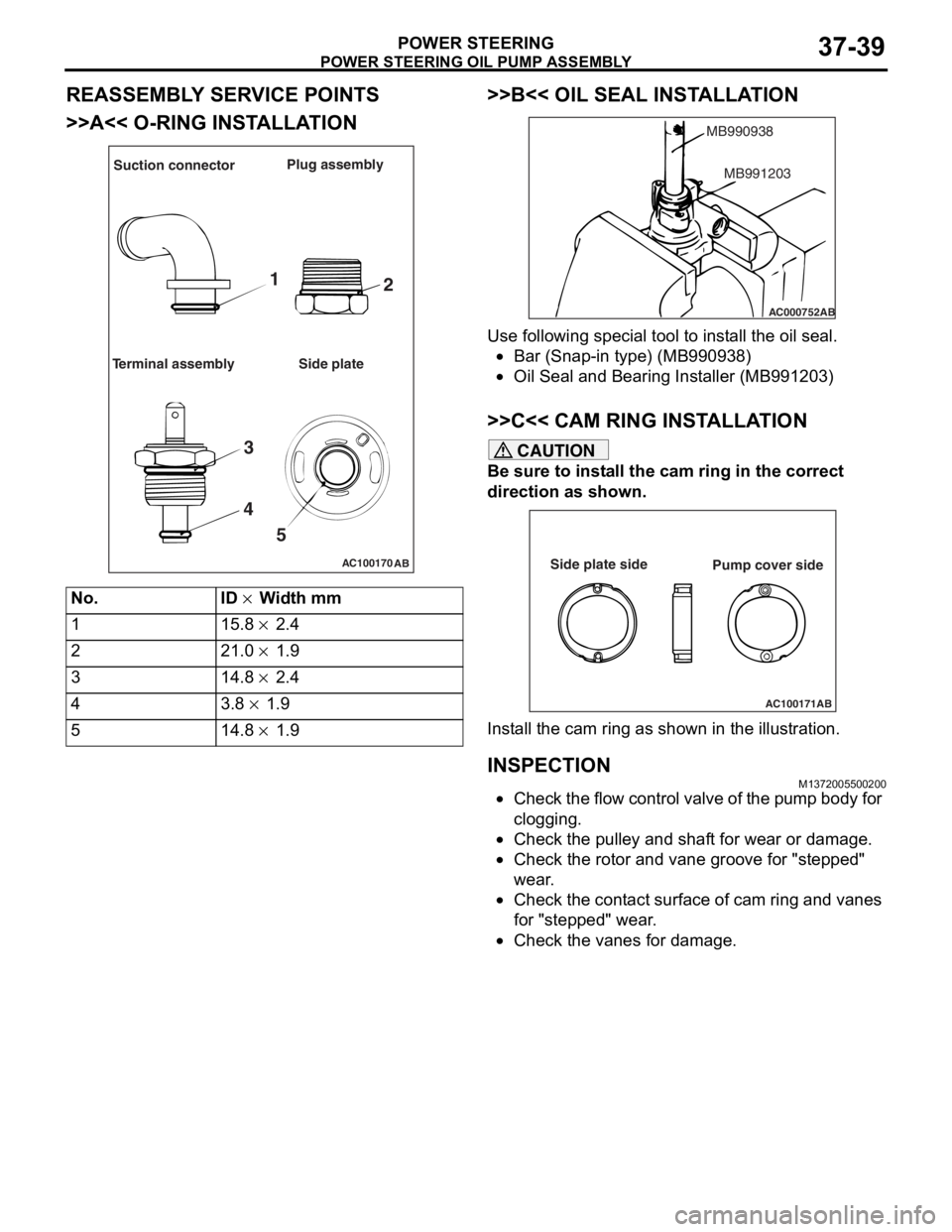
>>A<< O-RING INSTALLATION
AC100170AB
Suction connector Plug assembly
Terminal assembly Side plate
1 2
3
4 5
No.ID × Width mm
115.8 × 2.4
221.0 × 1.9
314.8 × 2.4
43.8 × 1.9
514.8 × 1.9
>>B<< OIL SEAL INST ALLA TION
AC000752
MB990938
AB
MB991203
Use following spe c ia l too l to inst all the oil seal.
•Bar (Snap-in type) (MB9909 38)
•Oil Seal and Bearin g Inst aller (MB9912 03)
>>C<< CAM RING INSTALLA TION
CAUTION
Be sure to install the cam ring in the correct
direction as shown.
AC100171AB
Side plate side
Pump cover side
Install the cam ring as shown in the illustration.
INSPECTION
M1372005500200
•Check the flow control valve of the pump body for
clogging.
•Check the pulley and shaft for wear or damage.
•Check the rotor and vane groove for "stepped"
wear.
•Check the contact surface of cam ring and vanes
for "stepped" wear.
•Check the vanes for damage.
Page 341 of 800
MOULDINGS
EXTERIOR51-9
ADHESIVE
M1511000500749
ApplicationSpecified adhesive
Front fender, front and rear door mouldingsDouble-sided tape: Generic products
[a: 6 mm width 1.2 mm thickness, b: 20 mm width 1.2
mm thickness]
MOULDINGS
REMOVAL AND INSTALLATIONM1511004700541
AC504995
Y0622AU
Y0624AUY0623AU
Y0729AU
W0740AU
Section A – A
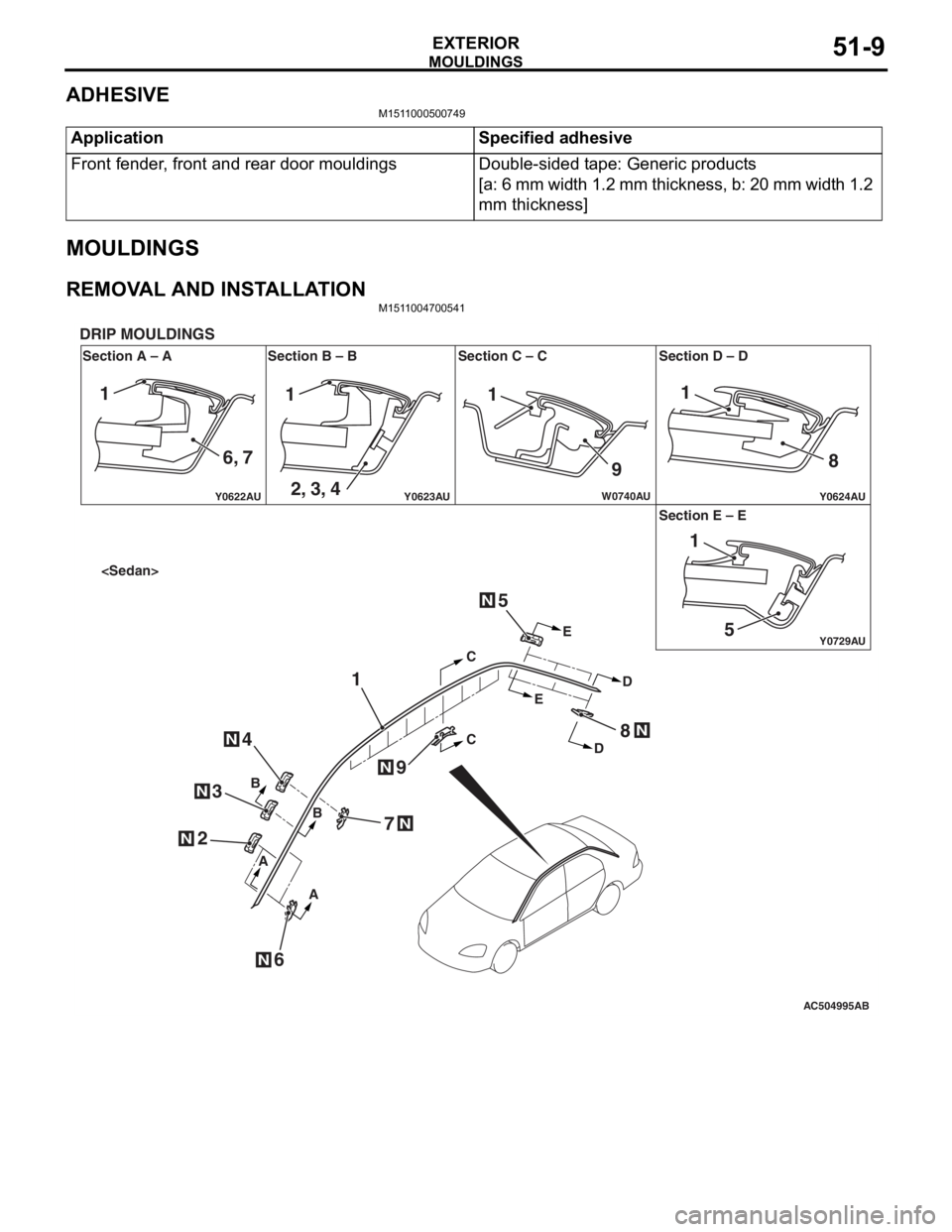
DRIP MOULDINGS
Section B – B Section C – C Section D – D
Section E – E
AB
N
N
N
N
N
CC
E E
D
D
B
B
A
A
1
2
6
4
3
5
7
8
9
N
N
N
111
9 8
51
1
6, 7 2, 3, 4
Page 344 of 800
AC504986 AC400117
AC400128
Section A – A
DOOR MOULDINGS
Section B – B Section C – C
AB
AA C
C
BB2
1
3
ClipClip
Boss
AC400840AE
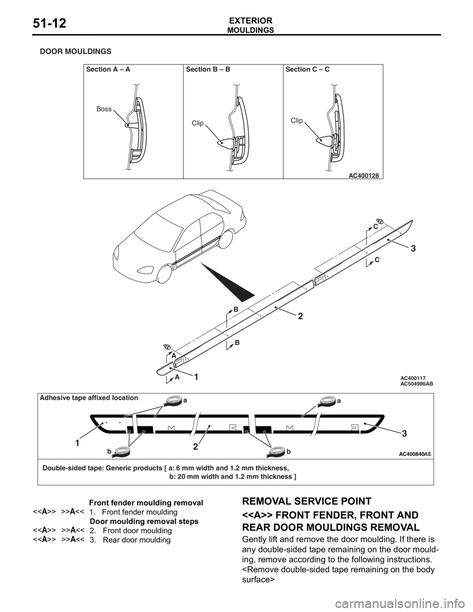
Double-sided tape: Generic products [ a: 6 mm width and 1.2 mm thickness, b: 20 mm width and 1.2 mm thickness ]
12
3
a
b
baAdhesive tape affixed location
Front fender moulding removal
<>>>A<<1.Front fender moulding
Door moulding removal steps
<>>>A<<2.Front door moulding
<>>>A<<3.Rear door moulding
MO
UL DI N G S
EXTERIOR51-12
REMOVA L SER VICE POINT
<> FRONT FENDER, FRONT AND
REAR DOOR MOULDINGS REMOV
A L
Gently lif t and remo ve th e door moulding . If the r e is
any d
ouble-sided t ape remainin g on th e door mould
-
ing, remove accord ing to the fo llowing in struction s .
Page 346 of 800
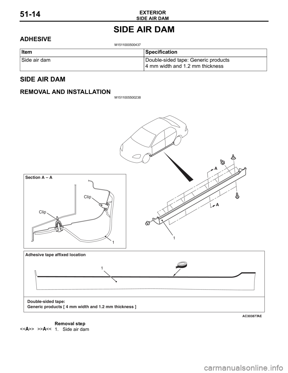
SIDE AIR DAM
EXTERIOR51-14
SIDE AIR DAM
ADHESIVEM1511000500437
ItemSpecification
Side air damDouble-sided tape: Generic products
4 mm width and 1.2 mm thickness
SIDE AIR DAM
REMOVAL AND INSTALLATIONM1511005500238
AC303877
Clip
Clip
Section A – A
AE
1
A
A
Adhesive tape affixed location
Double-sided tape:
Generic products [ 4 mm width and 1.2 mm thickness ] 1
1
Removal step
<>>>A<<1.Side air dam