MITSUBISHI LANCER RALLIART 2014 8.G Owners Manual
Manufacturer: MITSUBISHI, Model Year: 2014, Model line: LANCER RALLIART, Model: MITSUBISHI LANCER RALLIART 2014 8.GPages: 434, PDF Size: 57.5 MB
Page 121 of 434
Ignition switch 5-54 Features and controls
5
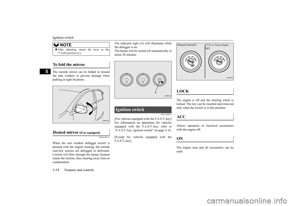
The outside mirror can be folded in toward the side window to prevent damage whenparking in tight locations.
N00549300175
When the rear window defogger switch is pressed with the engine running, the outside rearview mirrors are defogged or defrosted.Current will flow through the heater element inside the mirrors, thus clearing away frost or condensation.
The indicator light (A) will illuminate while the defogger is on. The heater will be turned off automatically in about 20 minutes.
N00512400615
[For vehicles equipped with the F.A.S.T.-key] For information on operations for vehicles equipped with the F.A.S.T.-key, refer to“F.A.S.T.-key: Ignition switch” on page 5-16. [Except for vehicles equipped with the F. A . S . T. - k e y ]
The engine is off and the steering wheel is locked. The key can be inserted and removedonly when the switch is in this position. Allows operation of electrical accessories with the engine off. The engine runs and all accessories can be used.
NOTE
After adjusting, return the lever to the “•”(off) position (C).
To fold the mirror Heated mirror
(if so equipped)
Ignition switch
LOCK ACC ON Manual transaxle
CVT or Twin Clutch SST
Page 122 of 434
Ignition switch
Features and controls 5-55
5
Engages the starter. After the engine starts, release the key and it will return automati-cally to the “ON” position.
N00539601097
After about 30 minutes has elapsed with theignition switch in the “ACC” position, the function automatically cuts out the power for the audio system and other electric devicesthat can be operated with that position. When the ignition switch is turned from the “ACC” position, the power is supplied againto those devices.
N00550900184
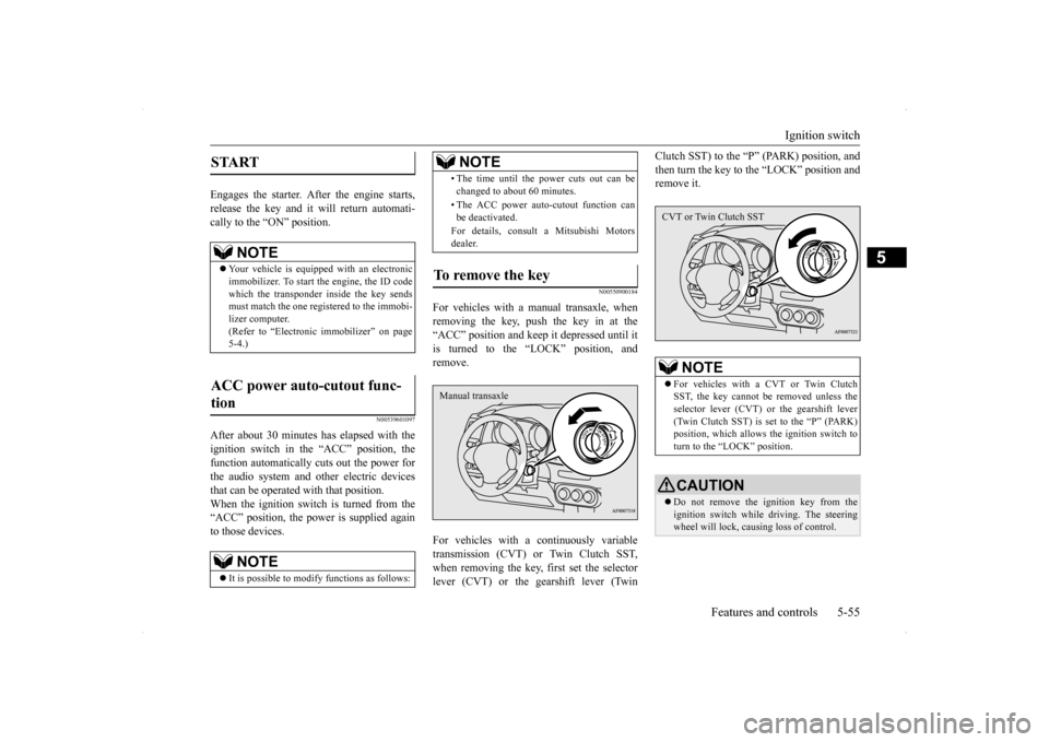
For vehicles with a manual transaxle, whenremoving the key, push the key in at the“ACC” position and keep it depressed until it is turned to the “LOCK” position, and remove. For vehicles with a continuously variable transmission (CVT) or Twin Clutch SST,when removing the key, first set the selector lever (CVT) or the gearshift lever (Twin
Clutch SST) to the “P
” (PARK) position, and
then turn the key to the “LOCK” position and remove it.
START
NOTE
Your vehicle is equipped with an electronic immobilizer. To start the engine, the ID code which the transponder inside the key sendsmust match the one registered to the immobi- lizer computer. (Refer to “Electronic immobilizer” on page5-4.)
ACC power auto-cutout func- tion
NOTE
It is possible to modify functions as follows:
• The time until the power cuts out can be changed to about 60 minutes. • The ACC power auto-cutout function can be deactivated. For details, consult a Mitsubishi Motors dealer.
To remove the key
NOTE
Manual transaxle
NOTE
For vehicles with a CVT or Twin Clutch SST, the key cannot be removed unless the selector lever (CVT) or the gearshift lever(Twin Clutch SST) is set to the “P” (PARK) position, which allows the ignition switch to turn to the “LOCK” position.CAUTION Do not remove the ignition key from the ignition switch while driving. The steering wheel will lock, causing loss of control.CVT or Twin Clutch SST
Page 123 of 434
![MITSUBISHI LANCER RALLIART 2014 8.G Owners Manual Steering wheel lock 5-56 Features and controls
5
N00512500195
[For vehicles equipped with the F.A.S.T.-key] For information on operations for vehiclesequipped with the F.A.S.T.-key, refer to “F.A.S. MITSUBISHI LANCER RALLIART 2014 8.G Owners Manual Steering wheel lock 5-56 Features and controls
5
N00512500195
[For vehicles equipped with the F.A.S.T.-key] For information on operations for vehiclesequipped with the F.A.S.T.-key, refer to “F.A.S.](/img/19/7490/w960_7490-122.png)
Steering wheel lock 5-56 Features and controls
5
N00512500195
[For vehicles equipped with the F.A.S.T.-key] For information on operations for vehiclesequipped with the F.A.S.T.-key, refer to “F.A.S.T.-key: Steering wheel lock” on page 5-20. [Except for vehicles equipped with the F. A . S . T. - k e y ]
Remove the key at the “LOCK” position. Turn the steering wheel until it is locked. Turn the key to the “ACC” position while moving the steering wheel slightly.
N00542100060
Do not operate the starter motor continu- ously for longer than 15 seconds as thiscould run the battery down or damage the starter motor. If the engine does not start, turn the ignition switch back to the“LOCK” position, wait a few seconds, and then try again. Trying repeatedly with the engine or starter motor still turningwill damage the starter mechanism. If the engine will not start because the bat- tery is weak or discharged, refer to“Jump-starting the engine” (on page 8-2) for instructions.
If the engine is turned off while driving, the power brake booster will stop functioning and braking efficiency will be reduced. Also, the power steering system will not function and it will require greater effort to manuallysteer the vehicle. Do not leave the key in the “ON” position for a long time when the engine is not running. This will cause the battery to run down. Do not turn the key to the “START” position when the engine is running. It will damage the starter motor.
Steering wheel lock
CAUTION
To l o c k To u n l o c k
CAUTION Remove the key when leaving the vehicle.
NOTE
If the front wheels are turned, the anti-theft lock may sometimes make it difficult to turn the key from “LOCK” position to “ACC” position. Firmly turn the steering wheel to the left or to the right as you turn the key.
Starting and stopping the engine Tips for starting
Page 124 of 434
![MITSUBISHI LANCER RALLIART 2014 8.G Owners Manual Starting and stopping the engine Features and controls 5-57
5
[Except for vehicles equipped with the turbocharger] The engine is warmed up enough for driv- ing when the bar graph of engine coolant MITSUBISHI LANCER RALLIART 2014 8.G Owners Manual Starting and stopping the engine Features and controls 5-57
5
[Except for vehicles equipped with the turbocharger] The engine is warmed up enough for driv- ing when the bar graph of engine coolant](/img/19/7490/w960_7490-123.png)
Starting and stopping the engine Features and controls 5-57
5
[Except for vehicles equipped with the turbocharger] The engine is warmed up enough for driv- ing when the bar graph of engine coolanttemperature display starts to move. A lon- ger warm up period will only consume extra fuel. [For vehicles equipped with the turbo- charger] The engine is warmed up enough for driv-ing when the bar graph of engine coolanttemperature display starts to move. Driv- ing before the bar graph moves may cause deterioration of turbocharger performanceand driveability. A longer warm up period will only consume extra fuel. On vehicles equipped with the Twin Clutch SST, the following may occur after the engine is started, but they do not indi- cate an abnormality.• You may hear operational sounds of the Twin Clutch SST and you may feel vibration in the vehicle body.• If you shift the gearshift lever into the “N” (NEUTRAL) position and depress the accelerator pedal, increases in theengine speed will be limited.
N00542200146
[For vehicles equipped with the F.A.S.T.-key.]For information on operation for vehicles equipped with the F.A.S.T.-key, refer to “F.A.S.T.-key: Starting the engine” on page5-20. [Except for vehicles equipped with the F. A . S . T. - k e y. ]Your vehicle is equipped with an electroni- cally controlled fuel injection system, which automatically controls the release of fuel.
There is usually no need to depress the accel- erator pedal when starting the engine. The starter should not be run for more than 15 seconds at a time.To prevent battery drain, wait a few seconds between attempts to restart the engine. 1. Make sure all occupants are properly seated with seat belts fastened 2. Insert the ignition key. 3. Make sure the parking brake is applied.4. Press and hold the brake pedal down withyour right foot. 5. Press and hold the clutch pedal all the way down (manual transaxle).
WA R N I N G Never run the engine in a closed or poorly ventilated area any longer than is needed to move your vehicle out of the area. Car- bon monoxide gas, which is odorless and extremely poisonous, could build up andcause serious injury or death.CAUTION Do not push-start the vehicle.Do not run the engine
at high rpms or drive
at high speeds until the engine has had a chance to warm up. Release the ignition switch as soon as the engine starts. Otherwise, the starter motorwill be damaged.
Starting the engine
NOTE
For models equipped with a manual trans- axle, the starter will not operate unless the clutch pedal is fully depressed (Clutch inter-lock). This is a safety feature.
Page 125 of 434

Starting and stopping the engine 5-58 Features and controls
5
6. On vehicles with manual transaxle, place the gearshift lever in the “N” (Neutral) position. On vehicles with continuously variabletransmission (CVT) or Twin Clutch SST, make sure the selector lever (CVT) or gearshift lever (Twin Clutch SST) is in the“P” (PARK) position. 7. Turn the ignition switch to the “ON” posi- tion and make certain that all warning lights are functioning properly beforestarting the engine. 8. Turn the ignition switch to the “START” position without pressing the acceleratorpedal. Release the key when the engine starts.
After several attempts, you may experience that the engine still does not start. 1. Make sure that all electric devices, such as lights, air conditioning blower and rear window defogger, are turned off. 2. While depressing the brake pedal on vehi-cles equipped with continuously variable transmission (CVT) or Twin Clutch SST or the clutch pedal on the vehiclesequipped with manual transaxle, press the accelerator pedal halfway and hold it there, then crank the engine. Release theaccelerator pedal, immediately after the engine starts.
3. If the engine still will not start, the engine could be flooded with too much gasoline. While depressing the brake pedal on vehi- cles equipped with CVT or Twin ClutchSST or the clutch pedal on the vehicles equipped with manual transaxle, push the accelerator pedal all the way down andhold it there, then crank the engine for 5 to 6 seconds. Return the ignition switch to the “LOCK” position and release theaccelerator pedal. Wait a few seconds, andthen crank the engine again for 5 to 6 sec- onds while depressing the brake pedal or the clutch pedal, but do not push theaccelerator pedal. Release the ignition key if the engine starts. If the engine fails to start, repeat these procedures. If theengine still will not start, contact your local Mitsubishi Motors dealer or a repair facility of your choice for assistance.
When the ambient temperature is -4 °F (-20 °C) or lower on vehicles with CVT, or -22 °F (-30 °C) or lower on vehicles with TwinClutch SST, it may not be possible to start
NOTE
On vehicles with CVT, the starter will not operate unless the selector lever is in the “P”(PARK) or “N” (NEUTRAL) position. On vehicles with Twin Clutch SST, the starter will not operate unless the gearshiftlever is in the “P” (PARK) position or the gearshift lever is in the “N” (NEUTRAL) position with the brake pedal depressed.For safety reasons, start the engine in the “P” (PARK) position so that the wheels are locked.
NOTE
Minor noises may be heard on engine start- up. These will disappear as the engine warms up.
When the engine is hard to start
Startability of continuously vari- able transmission (CVT) vehicles or Twin Clutch SST vehicles at extremely cold ambient tempera- ture
Page 126 of 434

Starting and stopping the engine Features and controls 5-59
5
from a standstill even with the selector lever (CVT) or the gearshift lever (Twin Clutch SST) in the “D” (DRIVE) position. This phenomenon occurs because the trans-axle has not warmed up sufficiently; it does not indicate a problem. If it occurs, place the selector lever (CVT) or the gearshift lever(Twin Clutch SST) in the “P” (PARK) posi- tion and let the engine idle for at least 10 min- utes.The transaxle will warm up, and you will beable to start normally. Do not leave the vehicle during warm-up operation.
N00547600015
At high altitude locations, the idle speed maybe higher. This is done in order to stabilizethe idle speed when the power steering sys- tem and other systems operate. It does not indicate a malfunction.
N00542300088
1. Bring the vehicle to a complete stop. 2. Fully engage the parking brake whiledepressing the brake pedal.
3. For vehicles with a manual transaxle, turn the ignition switch to the “LOCK” posi- tion to stop the engine, and then move the gearshift lever to the 1st (on a uphill) or“R” (Reverse) (on a downhill) position. For vehicles with continuously variable transmission (CVT) or Twin Clutch SST,place the selector lever (CVT) or the gear- shift lever (Twin Clutch SST) in the “P” (PARK) position, and then turn the igni-tion switch to the “LOCK” position tostop the engine.
Idle speed in high altitude area Stopping the engine
NOTE
For vehicles with Twin Clutch SST, the engine will stop and the vehicle power will turn off approximately 1 second after the ignition switch is turned to the “LOCK”; position. The reason for this is that, in the time from when the ignition switch is turned to the“LOCK” position until the engine stops, the gears inside the Twin Clutch SST disengage so that the engine will start smoothly thenext time it is started. Two clutches installed in the Twin Clutch SST alternately engage and disengage toachieve smooth shifting. In addition, the gear on the side with the free clutch is engaged, therefore, quick shifting isperformed. If the engine was stopped with the gear engaged like this, it would provide resistancethe next time the engine is started. Therefore, the gear disengages in the approximately 1- second period until the engine stops. For vehicles with Twin Clutch SST, do not operate the gearshift lever or the acceleratorpedal for approximately 1 second until the engine stops.
Page 127 of 434
Turbocharger operation (if so equipped) 5-60 Features and controls
5
N00537300051
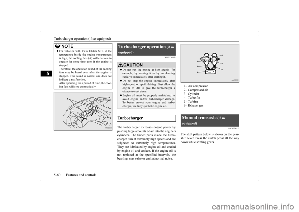
The turbocharger increases engine power by pushing large amounts of air into the engine’s cylinders. The finned parts inside the turbo-charger turn at extremely high speeds and are subjected to extremely high temperatures. They are lubricated by
engine oil and cooled
by engine oil and coolan
t. If the engine oil is
not replaced at the specified intervals, the bearings may seize or emit abnormal noise.
N00512700113
The shift pattern below is shown on the gear-shift lever. Press the clutch pedal all the waydown while shifting gears.
For vehicles with Twin Clutch SST, if the temperature inside the engine compartment is high, the cooling fans (A) will continue to operate for some time even if the engine is stopped.Therefore, the operation sound of the cooling fans may be heard even after the engine is stopped. This sound is normal and does notindicate a malfunction. After operating for a period of time, the cool- ing fans will stop automatically.NOTE
Turbocharger operation
(if so
equipped)
CAUTION Do not run the engine at high speeds (for example, by revving it or by acceleratingrapidly) immediately after starting it. Do not stop the engine immediately after high-speed or uphill driving. First allow the engine to idle to give the turbocharger a chance to cool down. Engine oil must be properly maintained to avoid engine and/or turbocharger damage.To better protect your engine and turbo- charger, use fully synthetic engine oil.
Turbocharger
1- Air compressor 2- Compressed air3- Cylinder 4- Turbo fin 5- Turbine6- Exhaust gasManual transaxle
(if so
equipped)
Page 128 of 434
Manual transaxle (if so equipped)
Features and controls 5-61
5
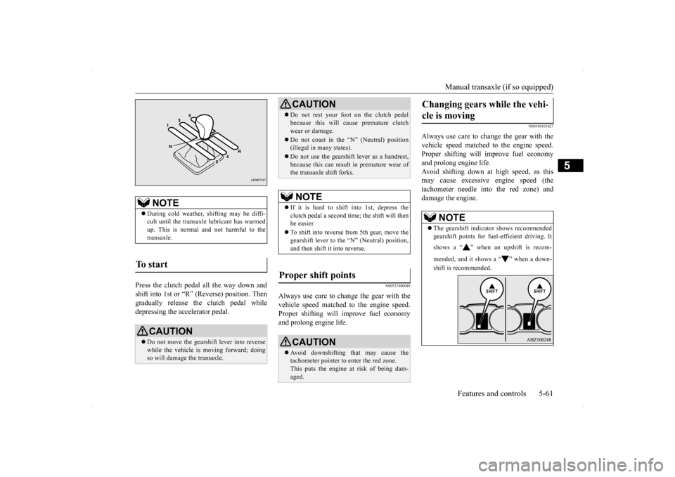
Press the clutch pedal all the way down and shift into 1st or “R” (Reverse) position. Then gradually release the clutch pedal while depressing the accelerator pedal.
N00537400049
Always use care to change the gear with the vehicle speed matched to the engine speed. Proper shifting will improve fuel economyand prolong engine life.
N00548101027
Always use care to change the gear with thevehicle speed matched to the engine speed. Proper shifting will improve fuel economy and prolong engine life.Avoid shifting down at high speed, as this may cause excessive engine speed (the tachometer needle into the red zone) anddamage the engine.
NOTE
During cold weather, shifting may be diffi- cult until the transaxle lubricant has warmed up. This is normal and not harmful to the transaxle.
To start
CAUTION Do not move the gearshift lever into reverse while the vehicle is moving forward; doing so will damage the transaxle.
Do not rest your foot on the clutch pedal because this will cause premature clutch wear or damage. Do not coast in the “N” (Neutral) position (illegal in many states). Do not use the gearshift lever as a handrest, because this can result in premature wear of the transaxle shift forks.NOTE
If it is hard to shift into 1st, depress the clutch pedal a second time; the shift will thenbe easier. To shift into reverse from 5th gear, move the gearshift lever to the “N” (Neutral) position, and then shift it into reverse.
Proper shift points
CAUTION Avoid downshifting that may cause the tachometer pointer to enter the red zone. This puts the engine at risk of being dam-aged.CAUTION
Changing gears while the vehi- cle is moving
NOTE
The gearshift indicator shows recommended gearshift points for fuel-efficient driving. It shows a “ ” when an upshift is recom- mended, and it shows a “ ” when a down- shift is recommended.
Page 129 of 434
Continuously variable transm
ission (CVT) (if so equipped)
5-62 Features and controls
5
N00512900131
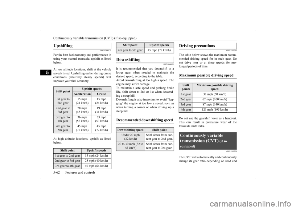
For the best fuel economy and performance in using your manual transaxle, upshift as listedbelow. At low altitude locations, shift at the vehicle speeds listed. Upshifting earlier during cruise conditions (relatively steady speeds) willimprove your fuel economy. At high altitude locations, upshift as listed below.
N00513000096
It is recommended that you downshift to a lower gear when needed to maintain the desired speed, according to the table.Avoid downshifting at too high a speed. The engine may suffer damage. To maintain a safe speed and prolong brakelife, shift down to 2nd or 1st when descend- ing a steep hill. Downshifting is also important to avoid “lug-ging” the engine at too low a speed, such aswhen turning a corner or when driving up a steep hill.
N00513100215
The table below shows the maximum recom- mended driving speed for in each gear. Donot drive near or at these speeds for pro- longed periods of time. Do not use the gearshift lever as a handrest. This can result in premature wear of the transaxle shift forks.
N00513200229
The CVT will automati
cally and continuously
change its gear ratio depending on road and
Upshifting
Shift point
Upshift speeds
Acceleration
Cruise
1st gear to 2nd gear
15 mph (24 km/h)
15 mph (24 km/h)
2nd gear to 3rd gear
28 mph (45 km/h)
19 mph (31 km/h)
3rd gear to 4th gear
36 mph (58 km/h)
33 mph (53 km/h)
4th gear to 5th gear
45 mph (72 km/h)
45 mph (72 km/h)
Shift point
Upshift speeds
1st gear to 2nd gear 15 mph (24 km/h)2nd gear to 3rd gear 25 mph (40 km/h)3rd gear to 4th gear 40 mph (64 km/h)
4th gear to 5th gear 45 mph (72 km/h)Downshifting
Recommended downshifting speed
Downshifting speed
Shift point
Under 20 mph (32 km/h)
Shift down from cur- rent gear to 2nd gear.
20 to 30 mph (32 to
48 km/h)
Shift down from cur- rent gear to 3rd gear.
Shift point
Upshift speeds
Driving precautions
Maximum possible driving speed
Shift points
Maximum possible driving
speed
1st gear 31 mph (50 km/h)2nd gear 62 mph (100 km/h)3rd gear 87 mph (140 km/h)4th gear 121 mph (195 km/h)Continuously variable transmission (CVT)
(if so
equipped)
Page 130 of 434
Continuously variable transmission (CVT) (if so equipped)
Features and controls 5-63
5
driving conditions. This helps achieve smooth driving and excellent fuel efficiency. Also you can manually shift up and shift down the transmission. Refer to “Sportsmode” on page 5-67. The transmission prevents unnecessary upshifts even when the accelerator pedal isreleased and ensures smooth driving. According to the condi
tions, the transmission
will automatically shift to a lower gear ratio to achieve stronger engine braking. This may help reduce your need to use the servicebrake.
N00513800384
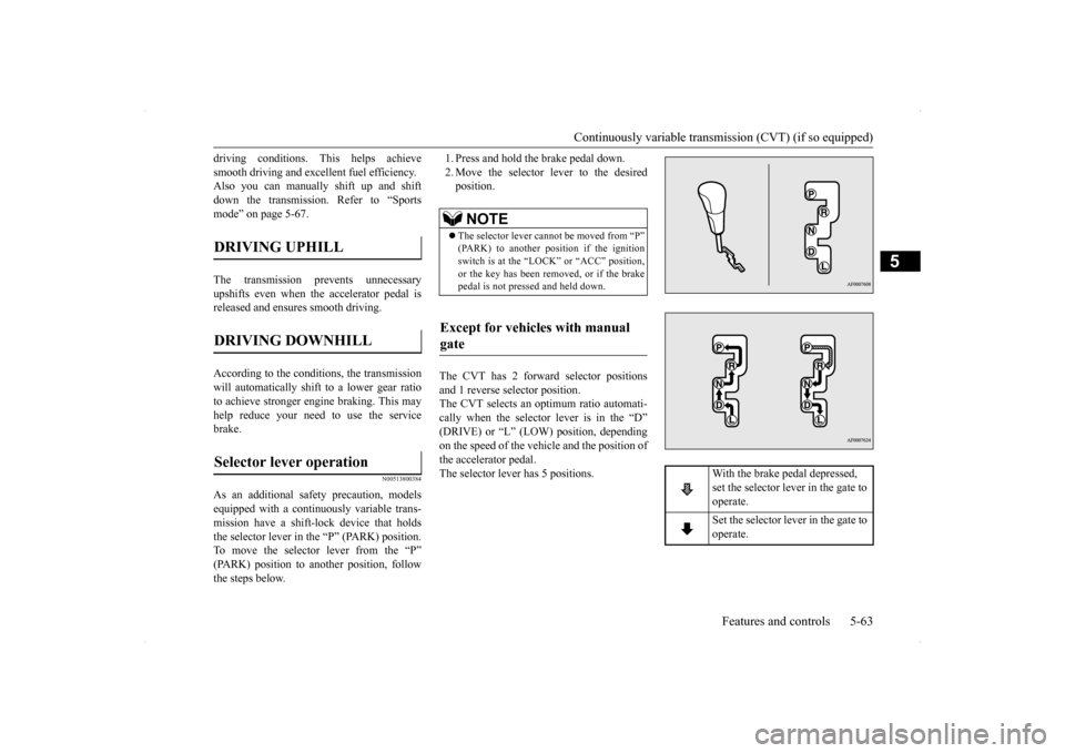
As an additional safety precaution, modelsequipped with a continuously variable trans- mission have a shift-lock device that holds the selector lever in the “P” (PARK) position.To move the selector lever from the “P” (PARK) position to another position, follow the steps below.
1. Press and hold the brake pedal down. 2. Move the selector lever to the desired position.
The CVT has 2 forward selector positions and 1 reverse selector position. The CVT selects an optimum ratio automati-cally when the selector lever is in the “D” (DRIVE) or “L” (LOW) position, depending on the speed of the vehicle and the position ofthe accelerator pedal. The selector lever has 5 positions.
DRIVING UPHILL
DRIVING DOWNHILL
Selector lever operation
NOTE
The selector lever cannot be moved from “P” (PARK) to another position if the ignition switch is at the “LOCK” or “ACC” position, or the key has been removed, or if the brakepedal is not pressed and held down.
Except for vehicles with manual gate
With the brake pedal depressed, set the selector lever in the gate to operate. Set the selector lever in the gate to operate.