fog light MITSUBISHI LANCER SE AWC 2014 8.G User Guide
[x] Cancel search | Manufacturer: MITSUBISHI, Model Year: 2014, Model line: LANCER SE AWC, Model: MITSUBISHI LANCER SE AWC 2014 8.GPages: 434, PDF Size: 57.5 MB
Page 125 of 434

Starting and stopping the engine 5-58 Features and controls
5
6. On vehicles with manual transaxle, place the gearshift lever in the “N” (Neutral) position. On vehicles with continuously variabletransmission (CVT) or Twin Clutch SST, make sure the selector lever (CVT) or gearshift lever (Twin Clutch SST) is in the“P” (PARK) position. 7. Turn the ignition switch to the “ON” posi- tion and make certain that all warning lights are functioning properly beforestarting the engine. 8. Turn the ignition switch to the “START” position without pressing the acceleratorpedal. Release the key when the engine starts.
After several attempts, you may experience that the engine still does not start. 1. Make sure that all electric devices, such as lights, air conditioning blower and rear window defogger, are turned off. 2. While depressing the brake pedal on vehi-cles equipped with continuously variable transmission (CVT) or Twin Clutch SST or the clutch pedal on the vehiclesequipped with manual transaxle, press the accelerator pedal halfway and hold it there, then crank the engine. Release theaccelerator pedal, immediately after the engine starts.
3. If the engine still will not start, the engine could be flooded with too much gasoline. While depressing the brake pedal on vehi- cles equipped with CVT or Twin ClutchSST or the clutch pedal on the vehicles equipped with manual transaxle, push the accelerator pedal all the way down andhold it there, then crank the engine for 5 to 6 seconds. Return the ignition switch to the “LOCK” position and release theaccelerator pedal. Wait a few seconds, andthen crank the engine again for 5 to 6 sec- onds while depressing the brake pedal or the clutch pedal, but do not push theaccelerator pedal. Release the ignition key if the engine starts. If the engine fails to start, repeat these procedures. If theengine still will not start, contact your local Mitsubishi Motors dealer or a repair facility of your choice for assistance.
When the ambient temperature is -4 °F (-20 °C) or lower on vehicles with CVT, or -22 °F (-30 °C) or lower on vehicles with TwinClutch SST, it may not be possible to start
NOTE
On vehicles with CVT, the starter will not operate unless the selector lever is in the “P”(PARK) or “N” (NEUTRAL) position. On vehicles with Twin Clutch SST, the starter will not operate unless the gearshiftlever is in the “P” (PARK) position or the gearshift lever is in the “N” (NEUTRAL) position with the brake pedal depressed.For safety reasons, start the engine in the “P” (PARK) position so that the wheels are locked.
NOTE
Minor noises may be heard on engine start- up. These will disappear as the engine warms up.
When the engine is hard to start
Startability of continuously vari- able transmission (CVT) vehicles or Twin Clutch SST vehicles at extremely cold ambient tempera- ture
Page 200 of 434
Indicator light, warning light, an
d information screen display list Features and controls 5-133
5
N00557700035 N00557800238
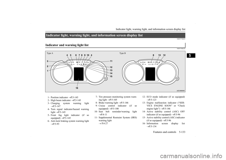
Indicator light, warning light, and information screen display list Indicator and warning light list Type A Type B1- Position indicator
P.5-145
2- High beam indicator
P.5-145
3- Charging system warning light
P.5-147
4- Turn signal indicator/hazard warning
light
P.5-145
5- Front fog light indicator (if so
equipped)
P.5-145
6- Anti-lock braking system warning light
P.5-93
7- Tire pressure monitoring system warn-
ing light
P.5-105
8- Brake warning light
P.5-146
9- Cruise control indicator (if so
equipped)
P.5-100
10- Seat belt reminder/warning light
P. 4 - 1 1
11- Supplemental Restraint System (SRS)
warning light P.4-27
12- ECO mode indicator (if so equipped)
P.5-123
13- Engine malfunction indicator (“SER-
VICE ENGINE SOON” or “Check engine light”)
P.5-146
14- Active stability
control (ASC) OFF
indicator (if so equipped)
P.5-96
15- Active stability control (ASC) indicator
(if so equipped)
P. 5 - 9 6
16- Information screen display list
P.5-134
Page 212 of 434
Indicators
Features and controls 5-145
5
The rest time can be set.
N00519900127 N00520000216
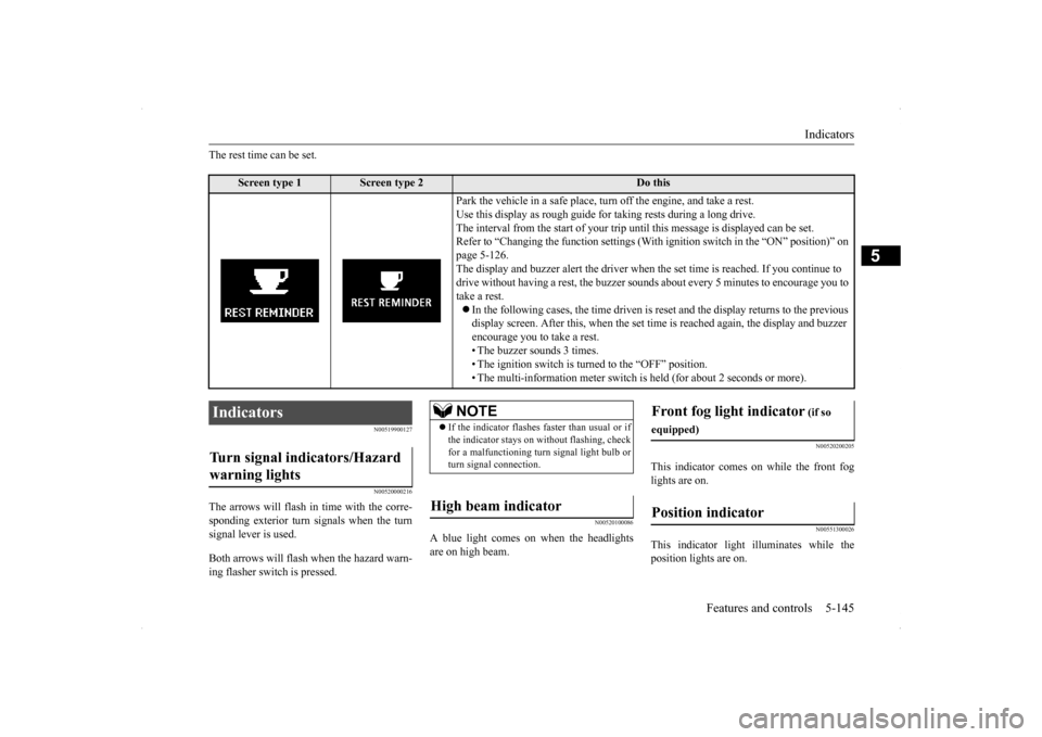
The arrows will flash in
time with the corre-
sponding exterior turn signals when the turnsignal lever is used. Both arrows will flas
h when the hazard warn-
ing flasher switch is pressed.
N00520100086
A blue light comes on when the headlightsare on high beam.
N00520200205
This indicator comes on while the front fog lights are on.
N00551300026
This indicator light illuminates while theposition lights are on.
Screen type 1
Screen type 2
Do this
Park the vehicle in a safe place, turn off the engine, and take a rest. Use this display as rough guide for taking rests during a long drive. The interval from the start of your trip un
til this message is displayed can be set.
Refer to “Changing the function settings (With
ignition switch in the “ON” position)” on
page 5-126. The display and buzzer alert the driver when the set time is reached. If you continue to drive without having a rest, the buzzer sounds
about every 5 minutes to encourage you to
take a rest. In the following cases, the time driven is re
set and the display returns to the previous
display screen. After this, when the set time
is reached again, the display and buzzer
encourage you to take a rest. • The buzzer sounds 3 times.• The ignition switch is turned to the “OFF” position. • The multi-information meter switch is
held (for about 2 seconds or more).
Indicators Turn signal indicators/Hazard warning lights
NOTE
If the indicator flashes faster than usual or if the indicator stays on without flashing, checkfor a malfunctioning turn signal light bulb or turn signal connection.
High beam indicator
Front fog light indicator
(if so
equipped)Position indicator
Page 216 of 434
Combination headlights and dimmer switch
Features and controls 5-149
5
Type 2 If the engine oil pressure drops while the engine is running, the warning display is dis- played on the information screen in the multi-information display.
N00522501762
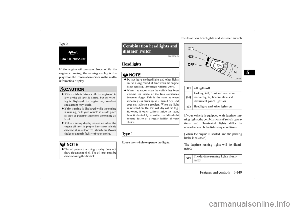
Rotate the switch to operate the lights.
If your vehicle is equipped with daytime run- ning lights, the combinations of switch opera- tions and illuminated lights differ inaccordance with the following conditions. [When the engine is started, and the parking brake is released] The daytime running lights will be illumi- nated:
CAUTION If the vehicle is driven while the engine oil is low, or the oil level is normal but the warn- ing is displayed, the engine may overheat and damage may result. If the warning is displayed while the engine is running, park your vehicle in a safe place as soon as possible and check the engine oil level. If this warning display comes on when the engine oil level is proper, have your vehiclechecked at an authorized Mitsubishi Motors dealer or a repair facility of your choice.NOTE
The oil pressure warning display does not show the amount of oil. The oil level must be checked using the dipstick.
Combination headlights and dimmer switch Headlights
NOTE
Do not leave the headlights and other lights on for a long period of time when the engine is not running. The battery will run down. When it rains, or when the vehicle has been washed, the inside of the lens sometimes becomes foggy. This is the same as whenwindow glass mists up on a humid day, and does not indicate a problem. When the light is switched on, the heat will dry out the fog.However, if water collects inside the light, have it checked by an authorized Mitsubishi Motors dealer or a repair facility of yourchoice.
Ty p e 1
OFF All lights off
Parking, tail, front and rear side- marker lights, license plate and instrument panel lights on Headlights and other lights on
OFF
The daytime running lights illumi- nated
Page 223 of 434
Front fog light switch (if so equipped) 5-156 Features and controls
5
N00522800377
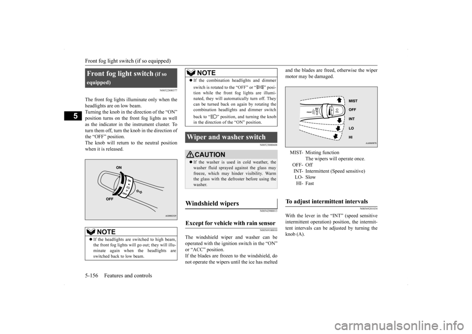
The front fog lights illuminate only when the headlights are on low beam. Turning the knob in the direction of the “ON” position turns on the front fog lights as wellas the indicator in the instrument cluster. To turn them off, turn the knob in the direction of the “OFF” position.The knob will return to the neutral positionwhen it is released.
N00523000608 N00542900013 N00569100010
The windshield wiper and washer can be operated with the ignition switch in the “ON” or “ACC” position. If the blades are frozen to the windshield, donot operate the wipers until the ice has melted
and the blades are freed, otherwise the wiper motor may be damaged.
N00569201034
With the lever in the “INT” (speed sensitiveintermittent operation) position, the intermit-tent intervals can be adjusted by turning the knob (A).
Front fog light switch
(if so
equipped)
NOTE
If the headlights are switched to high beam, the front fog lights will go
out; they will illu-
minate again when the headlights are switched back to low beam.
If the combination headlights and dimmer switch is rotated to the “OFF” or “ ” posi- tion while the front fog lights are illumi- nated, they will automatically turn off. Theycan be turned back on again by rotating the combination headlights and dimmer switch back to “ ” position, and turning the knob in the direction of the “ON” position.
Wiper and washer switch
CAUTION If the washer is used in cold weather, the washer fluid sprayed against the glass mayfreeze, which may hinder visibility. Warm the glass with the defroster before using the washer.
Windshield wipers Except for vehicle with rain sensor
NOTE
MIST- Misting function
The wipers will operate once.
OFF- Off INT- Intermittent (Speed sensitive)LO- SlowHI- Fast
To adjust intermittent intervals
Page 227 of 434
Electric rear window defogger switch 5-160 Features and controls
5
N00523500209
N00523700315
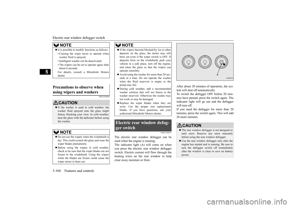
The electric rear window defogger can be used when the engine is running. The indicator light (A) will come on when you press the electric rear window defoggerswitch. Electric current will flow through the heating wires on the rear window to help clear away moisture or frost.
After about 20 minutes of operation, the sys- tem will shut off automatically. To switch the defogger OFF before 20 min-utes have passed, press the switch again. The indicator light will go out and the defogger will turn off. If you need the defogger for more than 20minutes, press the switch again. This will add 20 more minutes.
NOTE
It is possible to modify functions as follows: • Causing the wiper never to operate when washer fluid is sprayed. • Intelligent washer can be deactivated. • The wipers can be set to operate again after about 6 seconds. For details, consult a Mitsubishi Motors dealer.
Precautions to observe when using wipers and washers
CAUTION If the washer is used in cold weather, the washer fluid sprayed onto the glass might freeze, blocking your view. In cold weather,heat the glass with the defroster before using the washer.NOTE
Do not use the wipers when the windshield is dry. This could scratch the glass and wear the wiper blades prematurely. Before using the wipers in cold weather, check to be sure that the wiper blades are notfrozen to the windshield. Using the wipers while the blades are frozen could cause the wiper motor to burn out.
If the wipers become blocked by ice or other deposits on the glass, the motor may still burn out even if the wiper switch is OFF. If deposits form on the windshield, park your vehicle in a safe place, turn off the engine,and clean the glass so that the wipers can operate smoothly. Avoid using the washer for more than 20 sec- onds at a time. Do not operate the washer when the fluid reservoir is empty or thepump may fail. During cold weather, add a recommended washer solution that will not freeze in the washer reservoir. Otherwise the washer may not work or may be damaged. Replace the wiper blades when they are worn. Use the proper size replacementblades. If you have questions, ask your authorized Mitsubishi Motors dealer.
Electric rear window defog- ger switch
NOTE
CAUTION The rear window defogger is not designed to melt snow. Remove any snow manuallybefore using the rear window defogger. Use the rear window defogger only after the engine has started and is running. Be sure to turn the defogger switch off immediately after the window is clear to save on batterypower.
Page 228 of 434
Horn switch
Features and controls 5-161
5
N00523800156
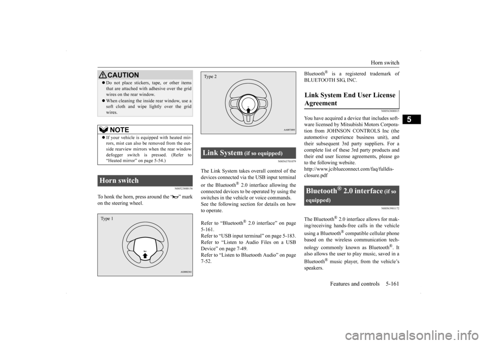
To honk the horn, press around the “ ” mark on the steering wheel.
N00563701079
The Link System takes overall control of thedevices connected via the USB input terminal or the Bluetooth
® 2.0 interface allowing the
connected devices to be operated by using theswitches in the vehicle or voice commands.See the following section for details on how to operate. Refer to “Bluetooth
® 2.0 interface” on page
5-161.Refer to “USB input terminal” on page 5-183. Refer to “Listen to Audio Files on a USB Device” on page 7-49.Refer to “Listen to Bluetooth Audio” on page 7-52.
Bluetooth
® is a registered trademark of
BLUETOOTH SIG, INC.
N00563800015
You have acquired a device that includes soft- ware licensed by Mitsubishi Motors Corpora- tion from JOHNSON CONTROLS Inc (theautomotive experien
ce business unit), and
their subsequent 3rd party suppliers. For a complete list of these 3rd party products and their end user license agreements, please goto the following website. http://www.jciblueconnect.com/faq/fulldis- closure.pdf
N00563901172
The Bluetooth
® 2.0 interface allows for mak-
ing/receiving hands-free calls in the vehicle using a Bluetooth
® compatible cellular phone
based on the wireless communication tech- nology commonly known as Bluetooth
®. It
also allows the user to
play music, saved in a
Bluetooth
® music player, from the vehicle’s
speakers.
Do not place stickers, tape, or other items that are attached with adhesive over the grid wires on the rear window. When cleaning the inside rear window, use a soft cloth and wipe lightly over the grid wires.NOTE
If your vehicle is equipped with heated mir- rors, mist can also be removed from the out-side rearview mirrors when the rear window defogger switch is pressed. (Refer to “Heated mirror” on page 5-54.)
Horn switch
CAUTION
Type 1
Link System
(if so equipped)
Type 2
Link System End User License Agreement
Bluetooth
® 2.0 interface
(if so
equipped)
Page 280 of 434
Heater without air conditioni
ng function (if so equipped) Comfort controls 7-5
7
N00738000044
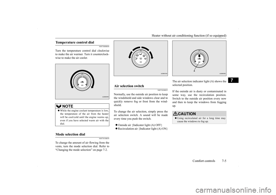
Turn the temperature control dial clockwise to make the air warmer. Turn it counterclock-wise to make the air cooler.
N00738100058
To change the amount of air flowing from thevents, turn the mode selection dial. Refer to“Changing the mode selection” on page 7-2.
N00738200033
Normally, use the outside air position to keepthe windshield and side windows clear and toquickly remove fog or frost from the wind- shield. To change the air selection, simply press the air selection switch. A sound will be made every time you push the switch. Outside air {Indicator light (A) OFF} Recirculation air {Indicator light (A) ON}
The air selection indicator light (A) shows the selected position. If the outside air is dusty or contaminated in some way, use the recirculation position.Switch to the outside air position every now and then to keep th
e windows from fogging
up.
Temperature control dial
NOTE
While the engine coolant temperature is low, the temperature of the air from the heater will be cool/cold until the engine warms up, even if you have selected warm air with thedial.
Mode selection dial
Air selection switch
CAUTION Using recirculated air for a long time may cause the windows to fog up.
Page 281 of 434
Heater without air conditioni
ng function (if so equipped)
7-6 Comfort controls
7
N00738300034
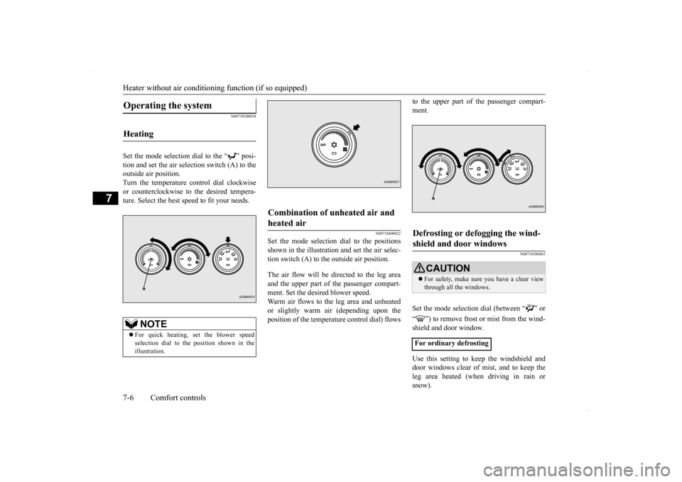
Set the mode selection dial to the “ ” posi- tion and set the air selection switch (A) to the outside air position.Turn the temperature control dial clockwiseor counterclockwise to the desired tempera- ture. Select the best speed to fit your needs.
N00738400022
Set the mode selection dial to the positionsshown in the illustration and set the air selec- tion switch (A) to the outside air position. The air flow will be di
rected to the leg area
and the upper part of the passenger compart-ment. Set the desired blower speed. Warm air flows to the leg area and unheated or slightly warm air (depending upon theposition of the temperat
ure control dial) flows
to the upper part of the passenger compart- ment.
N00738500065
Set the mode selection dial (between “ ” or “ ”) to remove frost or mist from the wind- shield and door window. Use this setting to keep the windshield and door windows clear of mist, and to keep the leg area heated (when driving in rain orsnow).
Operating the system
Heating
NOTE
For quick heating, set the blower speed selection dial to the position shown in the illustration.
Combination of unheated air and heated air
Defrosting or defogging the wind-shield and door windows
CAUTION For safety, make sure you have a clear view through all the windows.
For ordinary defrosting
Page 283 of 434
Manual air conditioning with
MAX A/C mode (if so equipped)
7-8 Comfort controls
7
N00736600219
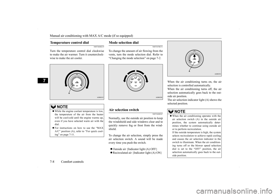
Turn the temperature control dial clockwise to make the air warmer. Turn it counterclock-wise to make the air cooler.
N00736700151
To change the amount of
air flowing from the
vents, turn the mode selection dial. Refer to“Changing the mode selection” on page 7-2.
N00736800367
Normally, use the outside air position to keepthe windshield and side windows clear and toquickly remove fog or frost from the wind- shield. To change the air selection, simply press the air selection switch. A sound will be madeevery time you push the switch. Outside air {Indicator light (A) OFF} Recirculated air {Indicator light (A) ON}
When the air conditioning turns on, the air selection is controlled automatically. When the air conditioning turns off, the airselection automatically goes back to the out- side air position. The air selection indicator light (A) shows theselected position.
Temperature control dial
NOTE
While the engine coolant temperature is low, the temperature of the air from the heater will be cool/cold until the engine warms up, even if you have selected warm air with thedial. For instructions on how to use the “MAX A/C” position (A), refer to “For quick cool- ing” on page 7-11.
Mode selection dial
Air selection switch
NOTE
When the air conditioning operates with the air selection switch (A) in the outside air position, the system automatically deter-mines whether to continue using outside air or to perform recirculation. If the outside temperature is high, the systemselects recirculation to achieve rapid cooling and causes the air selection indicator in the switch to illuminate. When the air condition-ing turns off or the blower speed selection dial is set to the “OFF” position, the air selection automatically goes back to the out-side position.