ABS MITSUBISHI LANCER SE AWC 2014 8.G Owners Manual
[x] Cancel search | Manufacturer: MITSUBISHI, Model Year: 2014, Model line: LANCER SE AWC, Model: MITSUBISHI LANCER SE AWC 2014 8.GPages: 434, PDF Size: 57.5 MB
Page 58 of 434
Supplemental Restraint System (SRS) - airbag
Seat and restraint systems 4-29
4
N00408000521
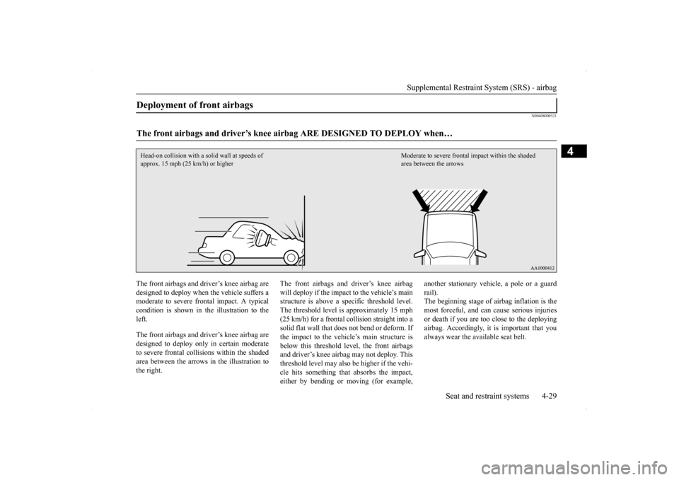
The front airbags and driver’s knee airbag are designed to deploy when the vehicle suffers a moderate to severe frontal impact. A typical condition is shown in th
e illustration to the
left. The front airbags and driver’s knee airbag are designed to deploy only in certain moderate to severe frontal collisions within the shadedarea between the arrows in the illustration to the right.
The front airbags and driver’s knee airbag will deploy if the impact to the vehicle’s main structure is above a specific threshold level. The threshold level is approximately 15 mph(25 km/h) for a frontal collision straight into a solid flat wall that does not bend or deform. If the impact to the vehicle’s main structure isbelow this threshold level, the front airbags and driver’s knee airbag may not deploy. This threshold level may also be higher if the vehi-cle hits something that absorbs the impact, either by bending or moving (for example,
another stationary vehicle, a pole or a guard rail). The beginning stage of airbag inflation is the most forceful, and can cause serious injuriesor death if you are too close to the deploying airbag. Accordingly, it is important that you always wear the available seat belt.
Deployment of front airbags The front airbags and driver’s knee airb
ag ARE DESIGNED TO DEPLOY when…
Head-on collision with a so
lid wall at speeds of
approx. 15 mph (25 km/h) or higher
Moderate to severe frontal
impact within the shaded
area between the arrows
Page 59 of 434
Supplemental Restraint System (SRS) - airbag 4-30 Seat and restraint systems
4
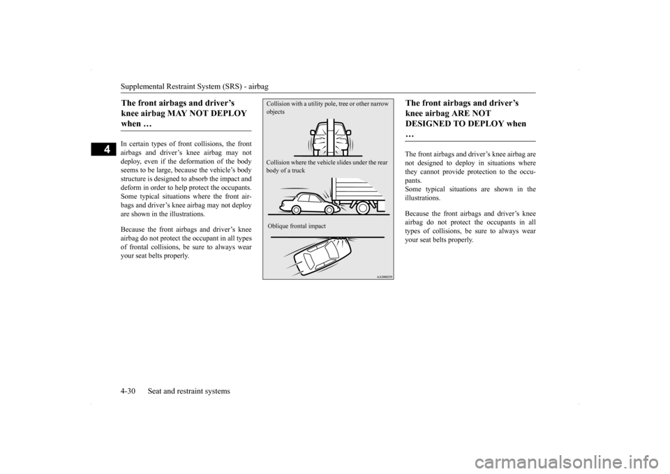
In certain types of fr
ont collisions, the front
airbags and driver’s knee airbag may not deploy, even if the deformation of the body seems to be large, because the vehicle’s bodystructure is designed to absorb the impact and deform in order to help protect the occupants. Some typical situations where the front air-bags and driver’s knee airbag may not deployare shown in the illustrations. Because the front airbags and driver’s knee airbag do not protect the occupant in all types of frontal collisions, be sure to always wearyour seat belts properly.
The front airbags and driver’s knee airbag are not designed to deploy in situations wherethey cannot provide protection to the occu- pants. Some typical situations are shown in theillustrations. Because the front airbags and driver’s knee airbag do not protect the occupants in all types of collisions, be sure to always wear your seat belts properly.
The front airbags and driver’s knee airbag MAY NOT DEPLOY when …
Collision where the vehicle
slides under the rear
body of a truck Oblique frontal impact Collision with a utility pol
e, tree or other narrow
objects
The front airbags and driver’s knee airbag ARE NOT DESIGNED TO DEPLOY when …
Page 64 of 434
Supplemental Restraint System (SRS) - airbag
Seat and restraint systems 4-35
4
N00408200507
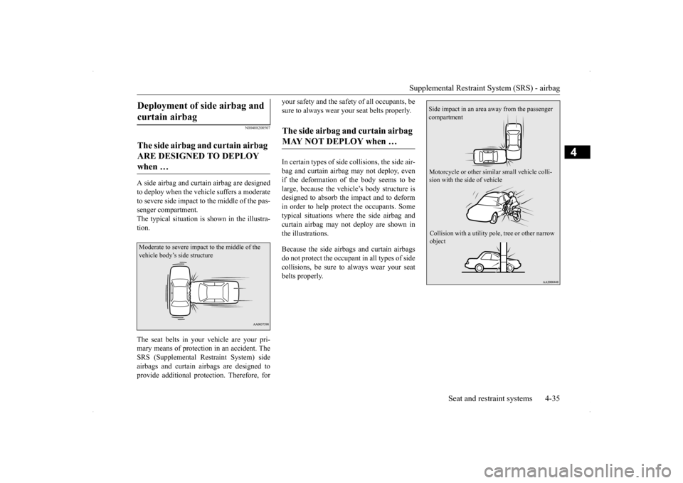
A side airbag and curtain airbag are designed to deploy when the vehicle suffers a moderateto severe side impact to the middle of the pas- senger compartment. The typical situation is shown in the illustra-tion. The seat belts in your vehicle are your pri- mary means of protection in an accident. The SRS (Supplemental Restraint System) sideairbags and curtain airbags are designed to provide additional protection. Therefore, for
your safety and the safety of all occupants, be sure to always wear your seat belts properly. In certain types of side
collisions, the side air-
bag and curtain airbag may not deploy, evenif the deformation of the body seems to be large, because the vehicle’s body structure is designed to absorb the impact and to deformin order to help protect the occupants. Sometypical situations where the side airbag and curtain airbag may not deploy are shown in the illustrations. Because the side airbags and curtain airbags do not protect the occupant in all types of side collisions, be sure to always wear your seat belts properly.
Deployment of side airbag and curtain airbag The side airbag and curtain airbag ARE DESIGNED TO DEPLOY when … Moderate to severe impact to the middle of the vehicle body’s side structure
The side airbag and curtain airbag MAY NOT DEPLOY when …
Side impact in an area away from the passenger compartment Motorcycle or other si
milar small vehicle colli-
sion with the side of vehicle Collision with a utility pole
, tree or other narrow
object
Page 160 of 434
Anti-lock braking system
Features and controls 5-93
5
When using the anti-lock brakes (sudden braking), steering is slightly different from normal driving conditions. Use thesteering wheel carefully. Always keep a safe distance from the vehicle in front of you. Even if your vehi-cle is equipped with the anti-lock braking system, leave a greater braking distance when:• Driving on gravel or snow-coveredroads. • Driving on uneven road surfaces. Operation of anti-lock braking system is not restricted to situations where brakes are applied suddenly. This system may also prevent the wheels from lockingwhen you drive over manholes, steel roadwork plates, road markings, or any uneven road surface. When the anti-lock braking system is in use, you may feel the brake pedal vibrat- ing and hear a unique sound. You mayalso feel as if the pedal resists being pressed. In this situation, simply hold the brakepedal down firmly. Do not pump the brake, which will result in reduced braking performance.
N00531600573
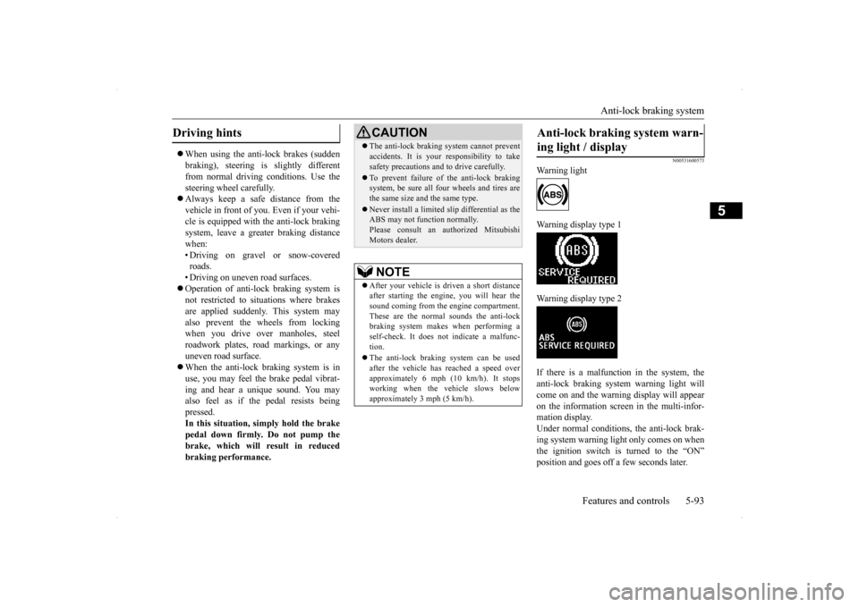
Warning light Warning display type 1 Warning display type 2 If there is a malfunction in the system, the anti-lock braking system warning light willcome on and the warning display will appearon the information screen in the multi-infor- mation display. Under normal conditions, the anti-lock brak-ing system warning light only comes on when the ignition switch is turned to the “ON” position and goes off a few seconds later.
Driving hints
CAUTION The anti-lock braking system cannot prevent accidents. It is your responsibility to take safety precautions and to drive carefully. To prevent failure of the anti-lock braking system, be sure all four wheels and tires are the same size and the same type. Never install a limited s
lip differential as the
ABS may not function normally. Please consult an authorized MitsubishiMotors dealer.NOTE
After your vehicle is driven a short distance after starting the engine, you will hear thesound coming from the engine compartment. These are the normal sounds the anti-lock braking system makes when performing aself-check. It does not indicate a malfunc- tion. The anti-lock braking system can be used after the vehicle has reached a speed over approximately 6 mph (10 km/h). It stopsworking when the vehicle slows below approximately 3 mph (5 km/h).
Anti-lock braking system warn- ing light / display
Page 162 of 434
Active Stability Control (ASC) (if so equipped)
Features and controls 5-95
5
N00529200022
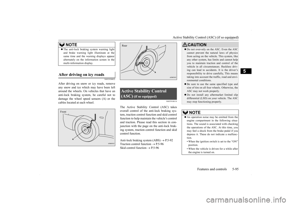
After driving on snow or icy roads, remove any snow and ice which may have been left around the wheels. On vehicles that have an anti-lock braking system, be careful not todamage the wheel speed sensors (A) or the cables located at each wheel.
N00559100118
The Active Stability Control (ASC) takesoverall control of the anti-lock braking sys- tem, traction control function and skid controlfunction to help maintain the vehicle’s controland traction. Please read
this section in con-
junction with the page on the anti-lock brak- ing system, traction control function and skidcontrol function. Anti-lock braking system (ABS)
P.5-92
Traction control function
P.5-96
Skid control function
P.5-96
NOTE
The anti-lock braking system warning light and brake warning light
illuminate at the
same time and the warning displays appear alternately on the information screen in the multi-information display.
After driving on icy roads Front
Active Stability Control (ASC)
(if so equipped)
Rear
CAUTION Do not over-rely on the ASC. Even the ASC cannot prevent the natural laws of physics from acting on the vehicle. This system, like any other system, has limits and cannot help you to maintain traction and control of thevehicle in all circumstances. Reckless driv- ing can lead to accidents. It is the driver’s responsibility to drive carefully, This meanstaking into account the traffic, road and envi- ronmental conditions. Be sure to use the same specified type and size of tire on all four wheels. Otherwise, the ASC may not work properly. Do not install any aftermarket limited slip differential (LSD) on your vehicle. The ASCmay stop functioning properly.NOTE
An operation noise may be emitted from the engine compartment in the following situa-tions. The sound is associated with checking the operations of the ASC. At this time, you may feel a shock from the brake pedal if youdepress it. These do not indicate a malfunc- tion. • When the ignition switch is set to the “ON” position. • When the vehicle is driven for a while after the engine is turned on.
Page 273 of 434
Trailer towing 6-12 Driving safety
6
N00630600102
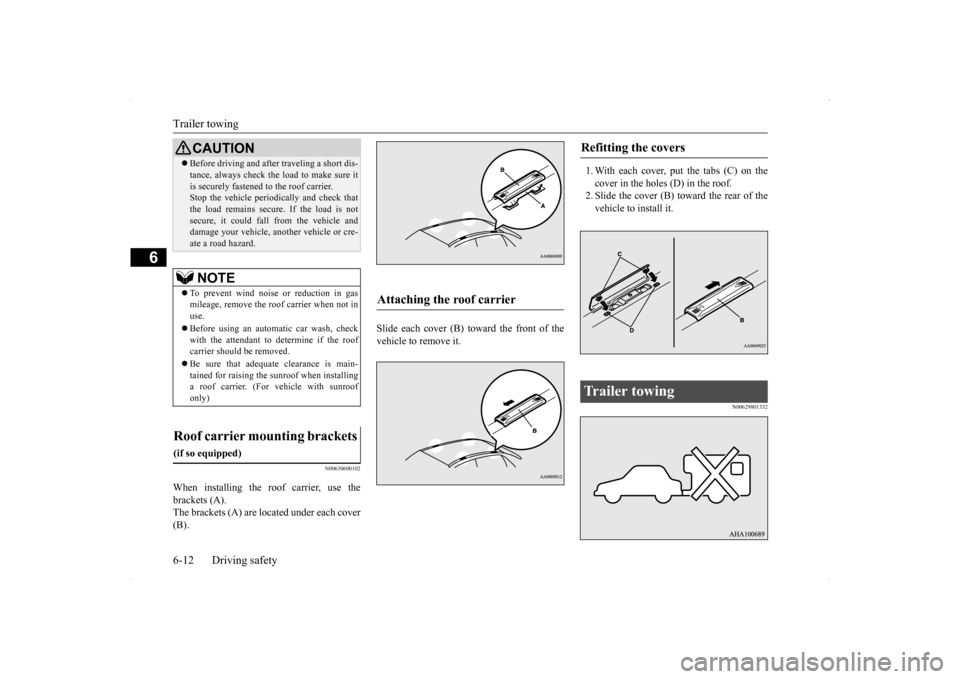
When installing the roof carrier, use the brackets (A). The brackets (A) are located under each cover (B).
Slide each cover (B) toward the front of the vehicle to remove it.
1. With each cover, put the tabs (C) on the cover in the holes (D) in the roof. 2. Slide the cover (B) toward the rear of thevehicle to install it.
N00629801332
Before driving and after traveling a short dis- tance, always check the load to make sure it is securely fastened to the roof carrier. Stop the vehicle periodically and check that the load remains secure. If the load is notsecure, it could fall from the vehicle and damage your vehicle, another vehicle or cre- ate a road hazard.NOTE
To prevent wind noise or reduction in gas mileage, remove the roof carrier when not in use. Before using an automatic car wash, check with the attendant to determine if the roof carrier should be removed. Be sure that adequate clearance is main- tained for raising the sunroof when installinga roof carrier. (For vehicle with sunroof only)
Roof carrier mounting brackets
(if so equipped)
CAUTION
Attaching the roof carrier
Refitting the covers
Trailer towing
Page 354 of 434
How to change a tire
For emergencies 8-13
8
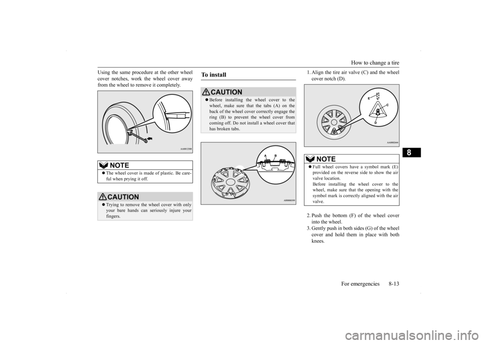
Using the same procedure at the other wheel cover notches, work the wheel cover away from the wheel to remove it completely.
1. Align the tire air valve (C) and the wheel cover notch (D). 2. Push the bottom (F) of the wheel cover into the wheel. 3. Gently push in both sides (G) of the wheel cover and hold them in place with bothknees.
NOTE
The wheel cover is made of plastic. Be care- ful when prying it off. CAUTION Trying to remove the wheel cover with only your bare hands can seriously injure your fingers.
To install
CAUTION Before installing the wheel cover to the wheel, make sure that the tabs (A) on the back of the wheel cover correctly engage the ring (B) to prevent the wheel cover fromcoming off. Do not install a wheel cover that has broken tabs.
NOTE
Full wheel covers have a symbol mark (E) provided on the reverse side to show the airvalve location. Before installing the wheel cover to the wheel, make sure that the opening with thesymbol mark is correctly aligned with the air valve.
Page 357 of 434
Operation under adverse driving conditions 8-16 For emergencies
8
the engine idle for a few minutes to cool the transaxle before trying again. If your vehicle is still stuck after several rock- ing attempts, call for a commercial tow truckservice.
When driving on a road covered with snow or ice, use snow tires. Tire chains cannot be used on your vehicle. There may be state or local regulations aboutusing snow tires. Always check the regu- lations in your local area before using them. Refer to the section entitled “Snowtires” on page 9-24 and “Tire chains” on page 9-24. Drive slowly. Do not make sudden starts or stops, sharp turns, or slam on the brakes. Allow extra distance between your vehi- cle and the vehicle in front of you, and avoid sudden braking. If a skid occurs when the accelerator pedal is depressed, take your foot off the pedal. Steer gently in the direction of the skid.
Your vehicle is equipped with an anti-lock braking system (ABS), hold the brake pedal down firmly and keep it depressed. Do not pump the brake pedal which willresult in reduced braking performance. After parking on snowy or icy road, it may be difficult to move your vehicle dueto freeze-up of the brake. Depress the accelerator pedal little by little to move the vehicle after confirming safety of thevehicle. Drive as slow as possible when driving on bumpy or rutted roads or over potholes etc.
WA R N I N G When trying to rock your vehicle out of a stuck position, make sure that there are no people nearby. The rocking motion canmake your vehicle suddenly lurch forward or backward, and injure any bystanders.
On wet roads
CAUTION Avoid flooded roads. Water is often deeper than it looks, and you could be seriously hurt by driving into flood water. When driving in rain, on water-covered roads, or through a car wash, water could get into the brake discs and make them fail tem-porarily. In such cases, lightly press the brake pedal to see if they are working prop- erly. If they are not, press the pedal lightly several times while driving to dry the brake pads or linings, then check them again.
When driving in rain, a layer of water may form between the tires and the road surface (aquaplaning). This loosens your tires’ grip on the road, making it difficult to steer or brake properly. When driving on a wet road:• Drive your vehicle at a safe speed.• Do not drive on worn tires.• Always keep the tires at the correct infla-tion pressures.
On snowy or icy roads
CAUTION
CAUTION Do not depress the accelerator pedal rapidly. The vehicle could start moving when it breaks free from the ice, possibly resulting inan accident.
On a bumpy or rutted road
CAUTION Driving on bumpy, rutted roads or over pot- holes can damage the tires and wheels.Wheels with low-profiles tires or under- inflated tires are especially at risk for dam- age.
Page 377 of 434
Tires 9-18 Vehicle care and maintenance
9
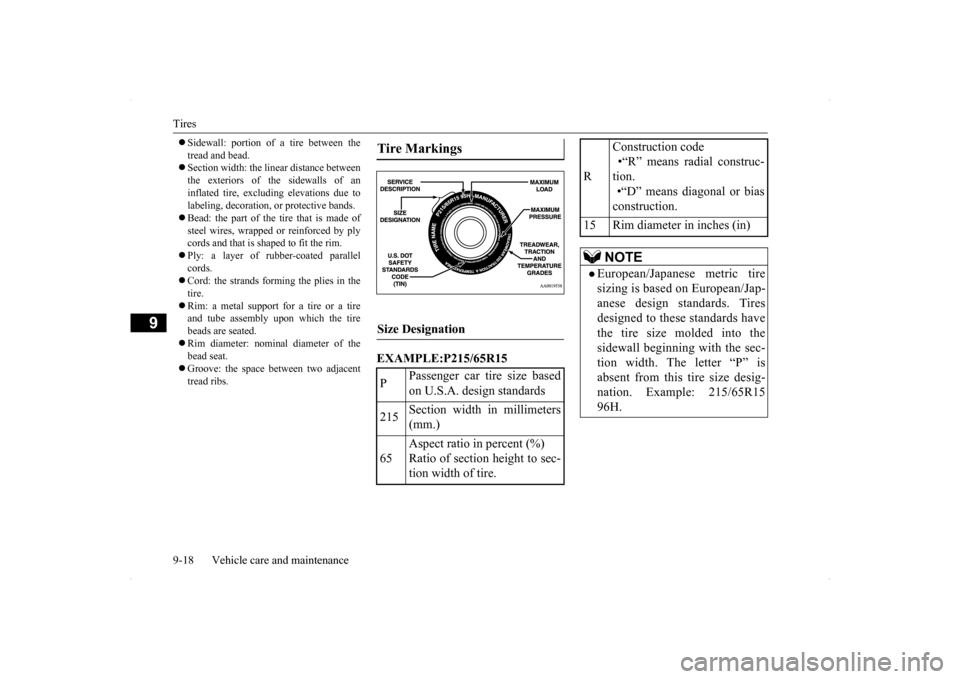
Sidewall: portion of a tire between the tread and bead. Section width: the linear distance between the exteriors of the sidewalls of aninflated tire, excluding elevations due to labeling, decoration, or protective bands. Bead: the part of the tire that is made of steel wires, wrapped or reinforced by ply cords and that is shaped to fit the rim. Ply: a layer of rubber-coated parallel cords. Cord: the strands forming the plies in the tire. Rim: a metal support for a tire or a tire and tube assembly upon which the tire beads are seated. Rim diameter: nominal diameter of the bead seat. Groove: the space between two adjacent tread ribs.
EXAMPLE:P215/65R15Tire Markings Size Designation P
Passenger car tire size based on U.S.A. design standards
215
Section width in millimeters (mm.)
65
Aspect ratio in percent (%) Ratio of section height to sec- tion width of tire.
R
Construction code •“R” means radial construc- tion. •“D” means diagonal or biasconstruction.
15 Rim diameter in inches (in)
NOTE
European/Japanese metric tire sizing is based on European/Jap- anese design standards. Tiresdesigned to these standards have the tire size molded into the sidewall beginning with the sec-tion width. The letter “P” is absent from this tire size desig- nation. Example: 215/65R1596H.
Page 415 of 434
Important facts to know in case of an accident 10-4 Customer assistance/Reporting Safety Defects
10
call (671)649-3673 or write to: To contact Triple J Motors call (670)234-7133 or write to: To contact Pacific Marketing Inc. call 684(699)9140 or write to:
N01047300229
We hope you will never be involved in an accident, but there is always that potential danger. So, please be sure to buckle up and drive safely. Remain calm. Check for injuries. Report all injuries to the police, and, if necessary, call for anambulance. Record all the details of the accident. This will provide you with accurate records ofthe accident for discussions with your insurance company and other persons who may be acting on your behalf.
Understand your repair estimate before approving repairs. Choosing the repair shop and the brands of parts that they use on your vehicle is your decision. Ask for genuine Mitsubishi Motors parts. Many times, to save money, your insur- ance company will recommend imitationparts that do not meet the original specifi-cations of fit, finish, corrosion resistance or workmanship.
The strength and integrity built into your Mit- subishi vehicle is the result of a specificdesign referred to as “Energy Management”. Individual body parts are designed to act as one unit in the event of an accident. Shockwaves are absorbed by protective panels or are channeled around the passenger compart- ment. This important feature is possiblebecause high tensile steel is used in Mitsubi- shi Motors panels and structural parts, some- thing that cannot be guaranteed by themanufacturers of imitation parts. All Genuine Mitsubishi Motors body panels and support
Triple J Enterprises, Inc. P.O. Box 6066 TA M U N I N G GUAM 96931
For vehicles sold in Saipan
Triple J Motors P.O. Box 500487 SAIPAN, MP96950-0487
For vehicles sold in American Samoa
Pacific Marketing, Inc. P.O. Box 698PA G O PA G O , AMERICAN SAMOA AS, 96799Important facts to know in case of an accident In the event of an accident
Key information to discuss with your insurance company Mitsubishi Motors built-in pro- tection