front brake MITSUBISHI LANCER SE AWC 2014 8.G Owners Manual
[x] Cancel search | Manufacturer: MITSUBISHI, Model Year: 2014, Model line: LANCER SE AWC, Model: MITSUBISHI LANCER SE AWC 2014 8.GPages: 434, PDF Size: 57.5 MB
Page 5 of 434
Instruments and controls 1-3 Overview
1
N00100202502
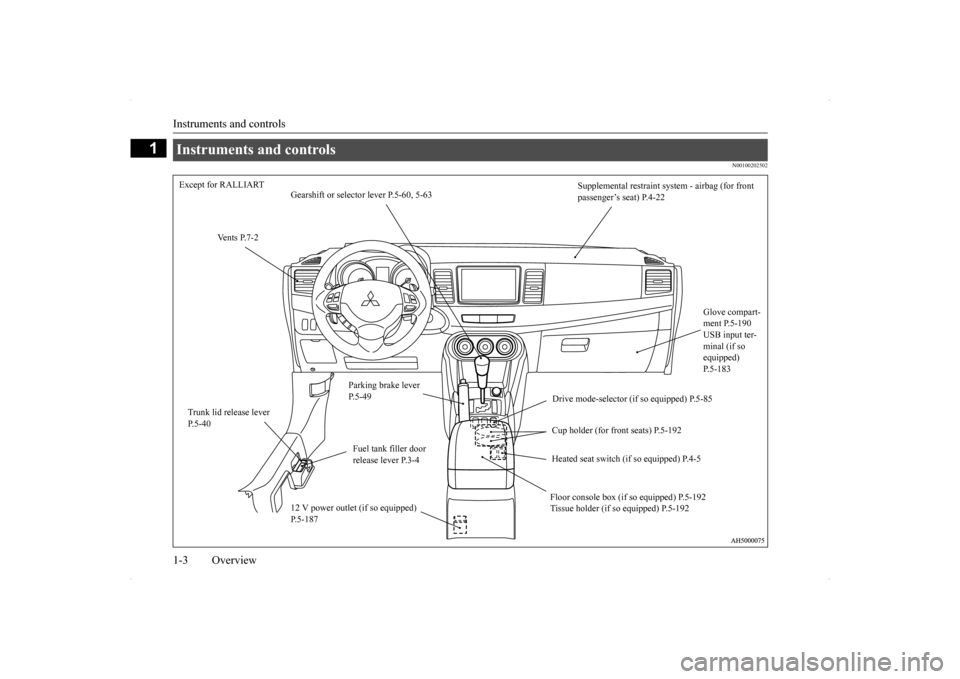
Instruments and controls Except for RALLIART
Supplemental restraint sy
stem - airbag (for front
passenger’s seat) P.4-22
Gearshift or selector lever P.5-60, 5-63
Vents P.7-2
Glove compart- ment P.5-190 USB input ter- minal (if so equipped) P.5-183
Parking brake lever P.5-49
Drive mode-selector (if so equipped) P.5-85
Trunk lid release lever P.5-40
Cup holder (for front seats) P.5-192
Fuel tank filler door release lever P.3-4
Heated seat switch (if so equipped) P.4-5 Floor console box (if so equipped) P.5-192 Tissue holder (if so equipped) P.5-192
12 V power outlet (if so equipped) P.5-187
Page 6 of 434
Instruments and controls
Overview 1-4
1
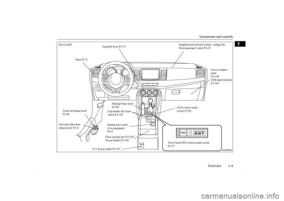
Supplemental restraint system - airbag (for front passenger’s seat) P.4-22
RALLIART
Gearshift lever P.5-71
Vents P.7-2
Glove compart- ment P.5-190USB input terminal P.5-183
Parking brake lever P.5-49
ACD control mode switch P.5-83
Trunk lid release lever P.5-40
Cup holder (for front seats) P.5-192 Heated seat switch (if so equipped) P.4-5
Fuel tank filler door release lever P.3-4
Floor console box P.5-192 Tissue holder P.5-192
Twin Clutch SST control mode switch P.5-77
12 V power outlet P.5-187
Page 52 of 434
Supplemental Restraint System (SRS) - airbag
Seat and restraint systems 4-23
4
• Seat belts reduce the risk of being thrown from your vehicle in a collision or rollover.
IT IS VERY IMPORTANT TO BE PROP- ERLY SEATED.• A driver or front passenger sitting tooclose to the steering wheel or instrument panel during airbag deployment can be seriously injured or killed.• Airbags inflate very quickly and withgreat force. If the driver and front pas-senger are not properly seated and restrained, the airbag may not provide the proper protection and can cause seri-ous injuries or death when it inflates.• To reduce the risk to the driver of seriousinjury or death due to a deploying driver’s airbag, always properly wear your seat belt and adjust the driver’s seatas far back as possible, maintaining a position that still allows the driver to have good control of the steering wheel,brake, accelerator, and other vehicle con- trols.• To reduce the risk to the front passengerof serious injury or death from a deploy- ing passenger’s airbag, make sure the passenger always wears the seat belt properly, remains seated upright and allthe way back in the seat, and positions the seat as far back as possible. WA R N I N G
• Seat all infants and children in the rearseat, properly restrained in an appropri- ate child restraint system.
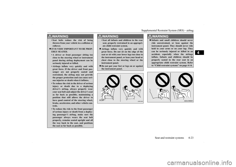
Airbags inflate very quickly and with great force. Do not sit on the edge of the seat or sit with your lower legs too close to the instrument panel, or lean your head orchest close to the steering wheel or the instrument panel. Do not put your feet or legs on or against the instrument panel.WA R N I N G
WA R N I N G Infants and small children should never ride unrestrained, or lean against the instrument panel. They should never ride held in your arms or on your lap. They can be seriously injured or killed in anaccident, especially when the airbags inflate. Infants and children should be properly seated in the rear seat in anappropriate child restraint system. Refer to “Child restraint systems” on page 4-14.
Page 54 of 434
Supplemental Restraint System (SRS) - airbag
Seat and restraint systems 4-25
4
The airbag control unit monitors the readiness of the electronic parts of the system whenever the ignition switch is in the “ON” or “START” position. These include all of theitems listed above and all related wiring. The airbags will operate only when the igni- tion switch is in the “ON” or “START” posi- tion. When the impact sensors detect a front or side impact sufficient to deploy the airbag(s),the appropriate airbag(s) will be deployed. When airbags deploy, some smoke is released accompanied by a loud noise. The smoke is not harmful, but do not intentionally inhale
the smoke as it may cause temporary irrita- tion to people with respiratory problems. After deployment, the airbags will quickly deflate, so quickly that some people may not even realize the airbags inflated.Airbag inflation does not prevent the driver from seeing or being able to steer the vehicle, and does not prevent people from leaving thevehicle.
N00418600230
This vehicle is equipped with an event datarecorder (EDR). The main purpose of an EDR is to record, in certain crash or near crash-like situations,such as an airbag deployment or hitting a road obstacle, data that will assist in under- standing how a vehicle’s systems performed.The EDR is designed to record data related to vehicle dynamics and safety systems for a
short period of time, typically 30 seconds or less. The EDR in this vehicle is designed to record such data as: How various systems in your vehicle were operating; Whether or not the driver and passenger safety belts were buckled/fastened; How far (if at all) the driver was depress- ing the accelerator and/or brake pedal;and, How fast the vehicle was traveling.
These data can help provide a better under- standing of the circumstances in whichcrashes and injuries occur. To read data recorded by an EDR, special equipment is required, and access to the vehi-
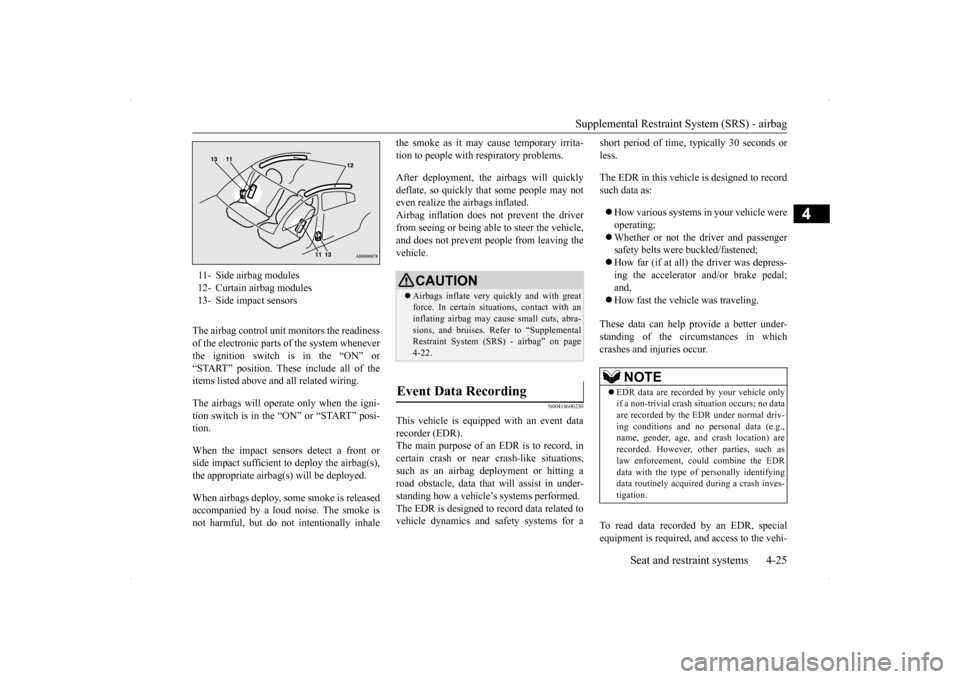
11- Side airbag modules 12- Curtain airbag modules13- Side impact sensors
CAUTION Airbags inflate very quickly and with great force. In certain situations, contact with an inflating airbag may cause small cuts, abra-sions, and bruises. Refer to “Supplemental Restraint System (SRS) - airbag” on page 4-22.
Event Data Recording
NOTE
EDR data are recorded by your vehicle only if a non-trivial crash situation occurs; no data are recorded by the EDR under normal driv- ing conditions and no personal data (e.g.,name, gender, age, and crash location) are recorded. However, other parties, such as law enforcement, could combine the EDR data with the type of personally identifying data routinely acquired during a crash inves-tigation.
Page 68 of 434
5
Features and controlsBreak-in recommendation
s ...............................................................5-3
Keys .....................................................
.............................................5-3
Electronic immobilizer (Anti-theft starting system) .........................5-4 Keyless entry system (if so equipped) ..............................................5-7Free-hand Advanced Security Transmitter (F.A.S.T.-key) (if so equipped)................................
.....................................................5-12
Door locks........................
...............................................................5-36
Power door locks .............
...............................................................5-38
“Child safety locks” for
rear door...................................................5-40
Trunk lid ....................................
.....................................................5-40
Inside emergency trunk lid
release .................................................5-42
Theft-alarm system ..........
...............................................................5-42
Power windows................
...............................................................5-45
Sunroof (if so equipped
) .........................................
........................5-47
Parking brake ...................
...............................................................5-49
Steering wheel tilt lock lever ..........................................................5-51Inside day/night rearview
mirror ....................................................5-51
Outside rearview mirr
ors ................................................................5-53
Ignition switch .................
...............................................................5-54
Steering wheel lock..........
...............................................................5-56
Starting and stopping the e
ngine ....................................................5-56
Turbocharger operation (if so equipped) ........................................5-60Manual transaxle (if so equipped) ..................................................5-60Continuously variable transmissi
on (CVT) (if so equipped)..........5-62
Twin Clutch SST (Sportronic Shif
t Transmission) (if so equipped)
...................................................................
..................................5-71
ACD (Active center differential system) (if so equipped)..............5-83 Electronically controlled 4WD system (if so equipped).................5-85
All-wheel driving opera
tion ........................................................... 5-87
Cautions on handling of all-wheel drive vehicles ......................... 5-89 Limited-slip differential (i
f so equipped) ....................................... 5-90
Service brake ..................
.................................................
............... 5-90
Brake assist system
................................................
......................... 5-91
Hill start assist (vehicles with
Twin Clutch SST) ........................... 5-91
Anti-lock braking syst
em ......................................
......................... 5-92
Active Stability Control (ASC
) (if so equipped) ............................ 5-95
Power steering system
...........................................
......................... 5-98
Cruise control (if so eq
uipped) ....................................................... 5-99
Tire pressure monitoring
system .................................................. 5-104
Rear-view camera (if so
equipped)..............
................................. 5-108
Instrument cluster ..........
.............................................................. 5-110
Multi-information display ............................................................ 5-112 Indicator light, warning light, and information screen display list
.................................................................
................................. 5-133
Indicators ..................................
.................................................... 5-145
Warning lights.................
.................................................
............. 5-146
Information screen disp
lay ....................................
....................... 5-147
Combination headlights and dimmer switch ................................ 5-149 Headlight leveling switch (if
so equipped)................................... 5-154
Turn signal lever ...
.................................................
....................... 5-154
Hazard warning flasher
switch ..................................................... 5-155
Front fog light switch (if so
equipped) ......................................... 5-156
Wiper and washer swit
ch ......................................
....................... 5-156
Electric rear window def
ogger switch .......................................... 5-160
Horn switch ..............................
.................................................... 5-161
Link System (if so equi
pped) ....................................................... 5-161
Page 92 of 434
Free-hand Advanced Security Transmit
ter (F.A.S.T.-key) (if so equipped)
Features and controls 5-25
5
2. Install the cover of the ignition switch. 3. Reinsert the emergency key into theF. A . S . T. - k e y.
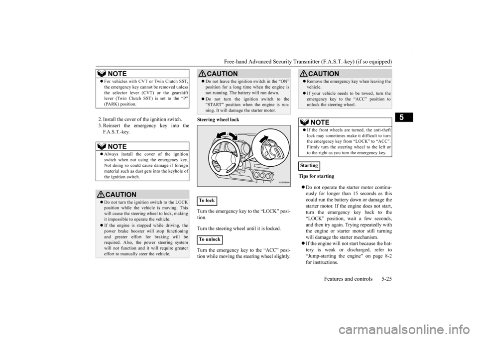
Steering wheel lock Turn the emergency key to the “LOCK” posi- tion. Turn the steering wheel until it is locked. Turn the emergency key to the “ACC” posi- tion while moving the steering wheel slightly.
Tips for starting Do not operate the starter motor continu- ously for longer than 15 seconds as this could run the battery down or damage the starter motor. If the engine does not start,turn the emergency key back to the “LOCK” position, wait a few seconds, and then try again. Trying repeatedly withthe engine or starter motor still turning will damage the starter mechanism. If the engine will not start because the bat- tery is weak or discharged, refer to “Jump-starting the engine” on page 8-2 for instructions.
NOTE
For vehicles with CVT or Twin Clutch SST, the emergency key cannot be removed unless the selector lever (CVT) or the gearshift lever (Twin Clutch SST) is set to the “P” (PARK) position.NOTE
Always install the cover of the ignition switch when not using the emergency key. Not doing so could cause damage if foreignmaterial such as dust
gets into the keyhole of
the ignition switch.CAUTION Do not turn the ignition switch to the LOCK position while the vehicle is moving. This will cause the steering wheel to lock, making it impossible to operate the vehicle. If the engine is stopped while driving, the power brake booster will stop functioning and greater effort for braking will be required. Also, the power steering systemwill not function and it will require greater effort to manually steer the vehicle.
Do not leave the ignition switch in the “ON” position for a long time when the engine is not running. The battery will run down. Do not turn the ignition switch to the “START” position when the engine is run- ning. It will damage the starter motor.
To l o c k To u n l o c k
CAUTION
CAUTION Remove the emergency key when leaving the vehicle. If your vehicle needs to be towed, turn the emergency key to the “ACC” position tounlock the steering wheel.NOTE
If the front wheels are turned, the anti-theft lock may sometimes make it difficult to turnthe emergency key from “LOCK” to “ACC”. Firmly turn the steering wheel to the left or to the right as you turn the emergency key.
Starting
Page 117 of 434
Parking brake 5-50 Features and controls
5
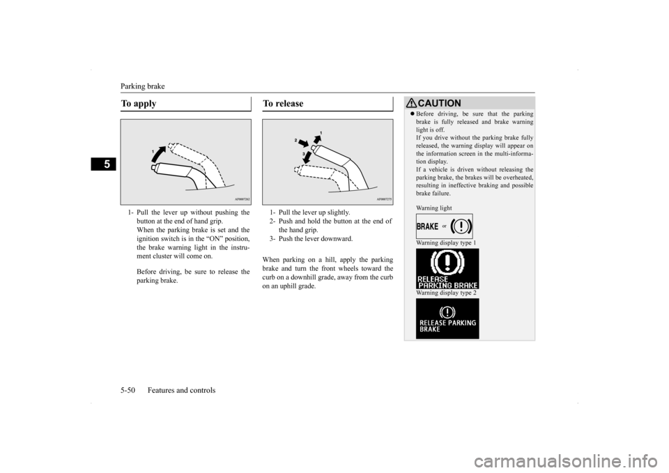
When parking on a hill, apply the parking brake and turn the front wheels toward thecurb on a downhill grade, away from the curb on an uphill grade.
To apply 1- Pull the lever up without pushing the
button at the end of hand grip. When the parking brake is set and theignition switch is in the “ON” position, the brake warning light in the instru- ment cluster will come on. Before driving, be sure to release the parking brake.
To r e l e a s e 1- Pull the lever up slightly. 2- Push and hold the button at the end of
the hand grip.
3- Push the lever downward.
CAUTION Before driving, be sure that the parking brake is fully released and brake warning light is off. If you drive without the parking brake fully released, the warning display will appear onthe information screen in the multi-informa- tion display. If a vehicle is driven without releasing theparking brake, the brakes will be overheated, resulting in ineffective braking and possible brake failure. Warning light Warning display type 1 Warning display type 2
Page 123 of 434
![MITSUBISHI LANCER SE AWC 2014 8.G Owners Manual Steering wheel lock 5-56 Features and controls
5
N00512500195
[For vehicles equipped with the F.A.S.T.-key] For information on operations for vehiclesequipped with the F.A.S.T.-key, refer to “F.A.S. MITSUBISHI LANCER SE AWC 2014 8.G Owners Manual Steering wheel lock 5-56 Features and controls
5
N00512500195
[For vehicles equipped with the F.A.S.T.-key] For information on operations for vehiclesequipped with the F.A.S.T.-key, refer to “F.A.S.](/img/19/7497/w960_7497-122.png)
Steering wheel lock 5-56 Features and controls
5
N00512500195
[For vehicles equipped with the F.A.S.T.-key] For information on operations for vehiclesequipped with the F.A.S.T.-key, refer to “F.A.S.T.-key: Steering wheel lock” on page 5-20. [Except for vehicles equipped with the F. A . S . T. - k e y ]
Remove the key at the “LOCK” position. Turn the steering wheel until it is locked. Turn the key to the “ACC” position while moving the steering wheel slightly.
N00542100060
Do not operate the starter motor continu- ously for longer than 15 seconds as thiscould run the battery down or damage the starter motor. If the engine does not start, turn the ignition switch back to the“LOCK” position, wait a few seconds, and then try again. Trying repeatedly with the engine or starter motor still turningwill damage the starter mechanism. If the engine will not start because the bat- tery is weak or discharged, refer to“Jump-starting the engine” (on page 8-2) for instructions.
If the engine is turned off while driving, the power brake booster will stop functioning and braking efficiency will be reduced. Also, the power steering system will not function and it will require greater effort to manuallysteer the vehicle. Do not leave the key in the “ON” position for a long time when the engine is not running. This will cause the battery to run down. Do not turn the key to the “START” position when the engine is running. It will damage the starter motor.
Steering wheel lock
CAUTION
To l o c k To u n l o c k
CAUTION Remove the key when leaving the vehicle.
NOTE
If the front wheels are turned, the anti-theft lock may sometimes make it difficult to turn the key from “LOCK” position to “ACC” position. Firmly turn the steering wheel to the left or to the right as you turn the key.
Starting and stopping the engine Tips for starting
Page 147 of 434
Twin Clutch SST (Sportronic Shif
t Transmission) (if so equipped)
5-80 Features and controls
5
When the gearshift lever is in the “D” (DRIVE) position, pull the +(SHIFT UP)sportronic steering wheel shifter toward youfor 2 seconds or more to return to “D” range operation.
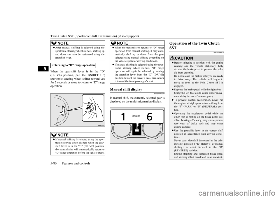
N00543000040
In manual shift, the currently selected gear isdisplayed on the multi-information display.
N00540800021
NOTE
After manual shifting is selected using the sportronic steering wheel shifters, shifting up and down can also be performed using the gearshift lever.
Returning to “D” range operation
NOTE
If manual shifting is selected using the spor- tronic steering wheel shifters when the gear- shift lever is in the “D” (DRIVE) position,the transmission will automatically return to “D” range operation before the vehicle stops.
�ç
When the transmission returns to “D” range operation from manual shifting, it may auto- matically shift up or down from the gear selected using manual shifting depending on the vehicle speed or driving conditions. If manual shifting is selected using the spor- tronic steering wheel shifters, “D” rangeoperation will again be selected by moving the gearshift lever from the “D” (DRIVE) position toward the driver’s seat, then returnit toward the front passenger’s seat.
Manual shift display
NOTE
through
Operation of the Twin Clutch SST
CAUTION Before selecting a position with the engine running and the vehicle stationary, fullydepress the brake pedal to prevent the vehi- cle from creeping. Do not release the brakes until you are readyto drive away. The vehicle will begin to move as soon as the Twin Clutch SST is engaged. Depress the brake pedal with the right foot. Using the left foot could cause driver move-ment delay in case of an emergency. To prevent sudden acceleration, never run the engine at high rpms when shifting from the “P” (PARK) or “N” (NEUTRAL) posi- tion. Operating the accelerator pedal while the other foot is resting on the brake pedal willaffect braking efficiency, may cause prema- ture wear of brake pads and may cause engine damage. Use the gearshift lever in the correct shift position in accordance with driving condi- tions. Never coast downhill backward in the driv-ing shift position { “D” (DRIVE) or manual shifting} or coast forward in the “R” (REVERSE) position.Engine stopping and increased brake pedal and steering effort could lead to an accident.
Page 155 of 434
All-wheel driving operation 5-88 Features and controls
5
traction when driving on slippery, wet or snow-covered roads a
nd when moving out of
mud. These vehicles, however, are not designedfor off-road use, and are unsuitable for driving on bumpy ground that may cause excessive strain.
Electronically controlled
4WD system vehicles should be driven only under the same conditions as are suitable for ordinary front-wheel drive vehicles. When turning a sharp corner in “4WD LOCK” position at low speed, a slight differ- ence in steering may be experienced similarto feeling as if the brakes were applied. This is called tight corner braking and results from each of the four tires being at a different dis-tance from the corner. The phenomenon is typical of 4-wheel drive vehicles. If this occurs, either straig
hten out the steering
wheel, or change to “2WD” or “4WD AUTO” mode. Set the drive mode-selector to “4WD AUTO” or “4WD LOCK” in accordance with the road conditions, and then gradually depress theaccelerator pedal for a smooth start.
Set the drive mode-selector to “4WD LOCK” and then gradually depress the accelerator pedal for a smooth start. Keep the pressure on the accelerator pedal asconstant as possible, and drive at low speed.
Turning sharp corners On snowy or icy roads
NOTE
The use of snow tires is recommended. Maintain a safe distance between vehicles, avoid sudden braking, and use engine brak- ing (downshifting).CAUTION Avoid sudden braking, sudden acceleration, and sharp turning. Skidding occurs and con- trol of the vehicle could be lost.
Moving out of mud
CAUTION If any of the following conditions occur, fol- low these procedures:• The engine coolant temperature display appears on the information screen in the multi-information display or the engine power drops suddenly. Refer to “Engine overheating” on page 8-4.
• The “ ” warning display or the “ ” warning display appear on the information screen in the multi-information display. Refer to “Warning display” on page 5-66.WA R N I N G When attempting to rock your vehicle out of a stuck position, be sure that the area around the vehicle is clear of people and physical objects. The rocking motion may cause the vehicle to suddenly launch for- ward/backward, causing injury or dam-age to nearby people or objects.NOTE
Avoid sudden braking, sudden acceleration and sharp turning; such operations couldresult in the vehicle becoming stuck. If the vehicle becomes stuck in muddy roads, it can often be moved with a rocking motion. Move the selector lever alternately between “D” (DRIVE) and “R” (REVERSE) posi-tions, while pressing
lightly on the accelera-
tor pedal.CAUTION