battery location MITSUBISHI MIRAGE G4 2018 Owner's Manual (in English)
[x] Cancel search | Manufacturer: MITSUBISHI, Model Year: 2018, Model line: MIRAGE G4, Model: MITSUBISHI MIRAGE G4 2018Pages: 263, PDF Size: 37.9 MB
Page 73 of 263

Free-hand Advanced
Security Transmitter (F.A.S
.T.-key) (if so equipped)
5-10 Features and controls
5
The operations possible with the F.A.S.T.- key can be modified as stated below. (Keyless entry operations are possible.) For details, contact an authorizedMitsubishi Motors dealer. • Enabling only the locking and unlocking of the doors and the opening of the trunklid • Enabling only the starting of the engine • Deactivating the F.A.S.T.-key
N00503201223
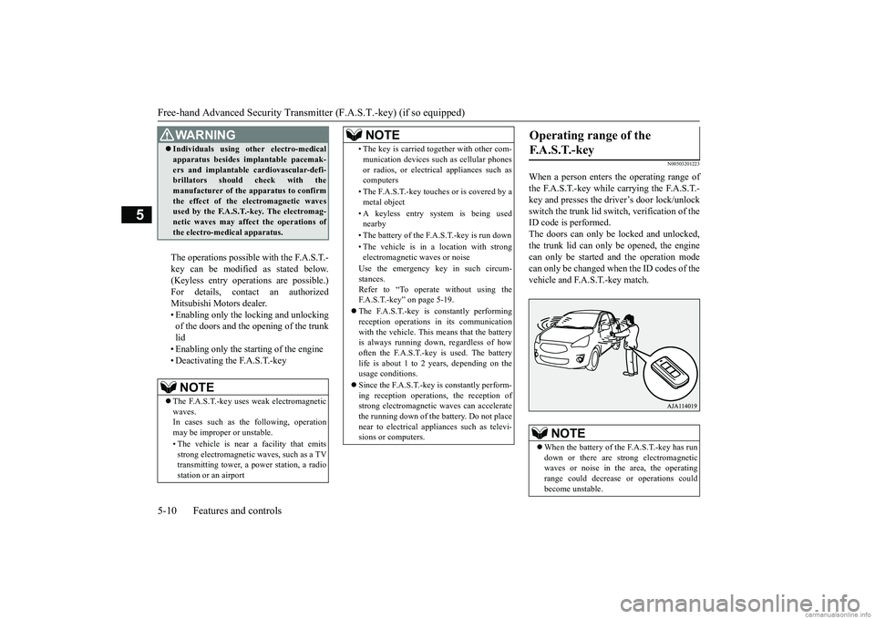
When a person enters the operating range ofthe F.A.S.T.-key while carrying the F.A.S.T.-key and presses the driver’s door lock/unlock switch the trunk lid switc
h, verification of the
ID code is performed.The doors can only be locked and unlocked, the trunk lid can only
be opened, the engine
can only be started and the operation mode can only be changed when the ID codes of the vehicle and F.A.S.T.-key match.
WA R N I N G Individuals using ot
her electro-medical
apparatus besides implantable pacemak-ers and implantable
cardiovascular-defi-
brillators should check with the manufacturer of the apparatus to confirm the effect of the electromagnetic wavesused by the F.A.S.T.-key. The electromag- netic waves may affect
the operations of
the electro-medical apparatus.NOTE
The F.A.S.T.-key uses weak electromagnetic waves. In cases such as the following, operation may be improper or unstable. • The vehicle is near a facility that emits strong electromagnetic
waves, such as a TV
transmitting tower, a pow
er station, a radio
station or an airport
• The key is carried together with other com- munication devices such
as cellular phones
or radios, or electrical appliances such ascomputers • The F.A.S.T.-key touches or is covered by a metal object • A keyless entry system is being used nearby • The battery of the F.A.S.T.-key is run down• The vehicle is in a location with strong electromagnetic
waves or noise
Use the emergency key in such circum- stances.Refer to “To operate without using the F.A.S.T.-key” on page 5-19. The F.A.S.T.-key is constantly performing reception operations
in its communication
with the vehicle. This means that the batteryis always running down, regardless of how often the F.A.S.T.-key is used. The battery life is about 1 to 2 years, depending on theusage conditions. Since the F.A.S.T.-key is constantly perform- ing reception operati
ons, the reception of
strong electromagnetic
waves can accelerate
the running down of the ba
ttery. Do not place
near to electrical appliances such as televi- sions or computers.NOTE
Operating range of the F. A . S . T. - k e y
NOTE
When the battery of the F.A.S.T.-key has run down or there are st
rong electromagnetic
waves or noise in the area, the operating range could decrease
or operations could
become unstable.
BK0249600US.book 10 ページ 2017年4月20日 木曜日 午後1時36分
Page 150 of 263

HomeLink® Wireless Control System (if so equipped)
Features and controls 5-87
5
N00584600029
Some garage door openers manufactured after 1995 have “rolling code protection”. To program a garage door openerequipped with “rolli
ng code protection”;
you will need to ac
cess the garage door
opener motor to press the motor’s “Learn”or “Smart” buttons.
For convenience, use
a ladder and another pe
rson to assist you.
It is recommended that a new battery be placed in the hand-held transmitter of the device being programmed to HomeLink
®
for quicker training and accurate trans- mission of the radio-frequency signal.
N00584700020
To program HomeLink
® to operate a garage
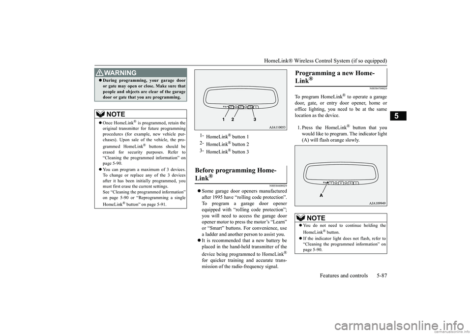
door, gate, or entry door opener, home oroffice lighting, you need to be at the same location as the device. 1. Press the HomeLink
® button that you
would like to program. The indicator light (A) will flash orange slowly.
During programming
, your garage door
or gate may open or close. Make sure thatpeople and objects are clear of the garagedoor or gate that you are programming.NOTE
Once HomeLink
® is programmed, retain the
original transmitter for future programming procedures (for example, new vehicle pur-chases). Upon sale of the vehicle, the pro- grammed HomeLink
® buttons should be
erased for security purposes. Refer to “Cleaning the programmed information” on page 5-90. You can program a ma
ximum of 3 devices.
To change or replace any of the 3 devicesafter it has been in
itially programmed, you
must first erase the current settings. See “Cleaning the programmed information”on page 5-90 or “Reprogramming a single HomeLink
® button” on page 5-91.
WA R N I N G
1-
HomeLink
® button 1
2-
HomeLink
® button 2
3-
HomeLink
® button 3
Before programming Home- Link
®
Programming a new Home- Link
®
NOTE
You do not need to continue holding the HomeLink
® button.
If the indicator light does not flash, refer to “Cleaning the programmed information” on page 5-90.
BK0249600US.book 87 ページ 2017年4月20日 木曜日 午後1時36分
Page 196 of 263

Jump-starting the engine For emergencies 8-3
8
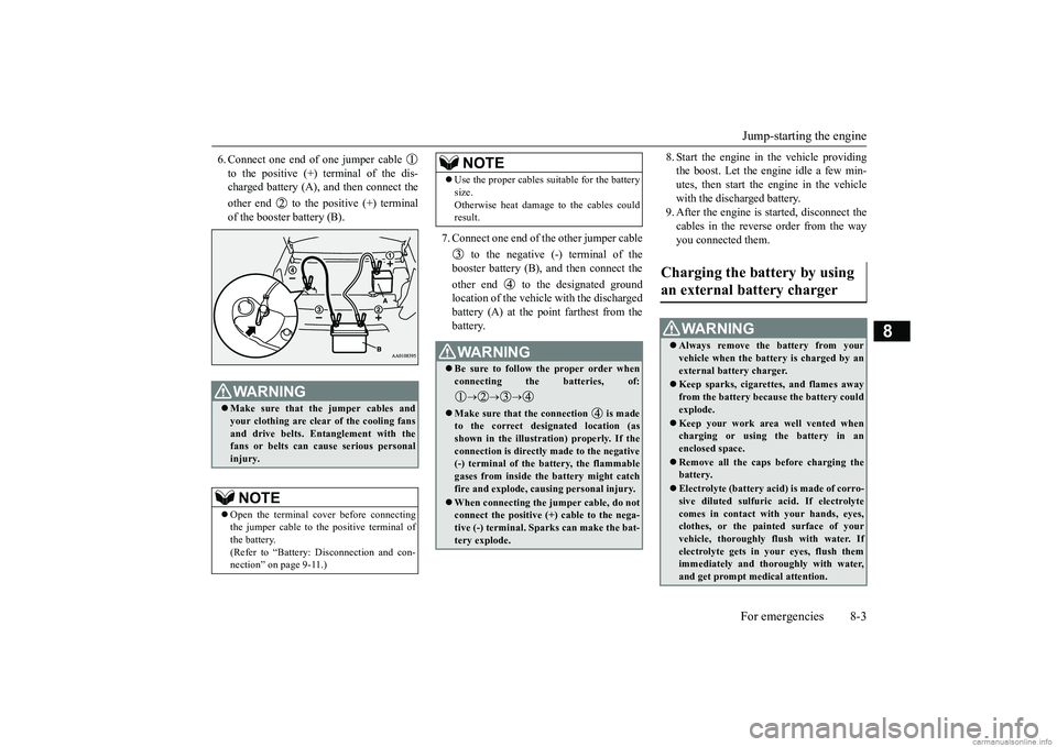
6. Connect one end of one jumper cable to the positive (+) terminal of the dis- charged battery (A),
and then connect the
other end to the positive (+) terminal of the booster battery (B).
7. Connect one end of the other jumper cable
to the negative (-) terminal of the booster battery (B), and then connect the other end to the designated ground location of the vehicle with the dischargedbattery (A) at the point farthest from the battery.
8. Start the engine in the vehicle providing the boost. Let the engine idle a few min-utes, then start the engine in the vehicle with the discharged battery. 9. After the engine is
started, disconnect the
cables in the reverse order from the way you connected them.
WA R N I N G Make sure that the jumper cables and your clothing are clear of the cooling fansand drive belts. Entanglement with the fans or belts can cause serious personal injury.NOTE
Open the terminal co
ver before connecting
the jumper cable to the positive terminal ofthe battery. (Refer to “Battery:
Disconnection and con-
nection” on page 9-11.)
Use the proper cables suitable for the battery size.Otherwise heat damage
to the cables could
result.WA R N I N G Be sure to follow the proper order when connecting the batteries, of:
Make sure that the connection is made to the correct designated location (asshown in the illustration) properly. If the connection is directly made to the negative (-) terminal of the battery, the flammablegases from inside the battery might catch fire and explode, caus
ing personal injury.
When connecting the jumper cable, do not connect the positive (+) cable to the nega- tive (-) terminal. Sparks can make the bat-tery explode.NOTE
Charging the battery by using an external battery charger
WA R N I N G Always remove the battery from your vehicle when the battery is charged by an external battery charger. Keep sparks, cigarettes, and flames away from the battery because the battery couldexplode. Keep your work area well vented when charging or using
the battery in an
enclosed space. Remove all the caps
before charging the
battery. Electrolyte (battery acid) is made of corro- sive diluted sulfuric acid. If electrolyte comes in contact with your hands, eyes,clothes, or the pain
ted surface of your
vehicle, thoroughly flush with water. If electrolyte gets in your eyes, flush themimmediately and thoroughly with water, and get prompt medical attention.
BK0249600US.book 3 ページ 2017年4月20日 木曜日 午後1時36分
Page 233 of 263

Fuses 9-24 Vehicle care and maintenance
9
Some fuses may not be installed on your vehicle, depending on the vehicle model or specifications.
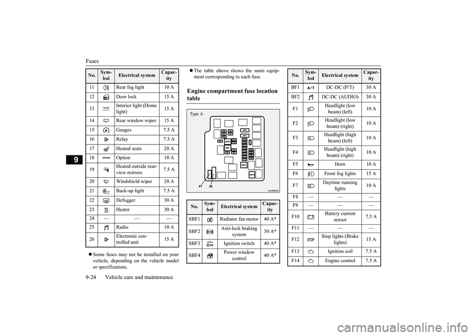
The table above show
s the main equip-
ment corresponding to each fuse.
11 Rear fog light 10 A 12 Door lock 15 A 13
Interior light (Dome light)
15 A
14 Rear window wiper 15 A 15 Gauges 7.5 A16 Relay 7.5 A 17 Heated seats 20 A 18 Option 10 A 19
Heated outside rear- view mirrors
7.5 A
20 Windshield wiper 20 A 21 Back-up light 7.5 A22 Defogger 30 A 23 Heater 30 A 24 — — — 25 Radio 10 A 26
Electronic con- trolled unit
15 A
No.
Sym- bol
Electrical system
Capac-ity
Engine compartment fuse location table No.
Sym- bol
Electrical system
Capac-ity
SBF1 Radiator fan motor 40 A
*
SBF2
Anti-lock braking
system
30 A
*
SBF3 Ignition switch 40 A
*
SBF4
Power window
control
40 A
*
Type A
BF1 DC-DC (P/T) 30 A BF2 DC-DC (AUDIO) 30 A F1
Headlight (low beam) (left)
10 A
F2
Headlight (low beam) (right)
10 A
F3
Headlight (high beam) (left)
10 A
F4
Headlight (high beam) (right)
10 A
F5 Horn 10 A F6 Front fog lights 15 A F7
Daytime running
lights
10 A
F8 — — — F9 — — — F10
Battery current
sensor
7.5 A
F11 — — —F12
Stop lights (Brake
lights)
15 A
F13 Ignition coil 7.5 A F14 Engine control 7.5 ANo.
Sym- bol
Electrical system
Capac-ity
BK0249600US.book 24 ページ 2017年4月20日 木曜日 午後1時36分