set clock MITSUBISHI MIRAGE G4 2018 Owner's Manual (in English)
[x] Cancel search | Manufacturer: MITSUBISHI, Model Year: 2018, Model line: MIRAGE G4, Model: MITSUBISHI MIRAGE G4 2018Pages: 263, PDF Size: 37.9 MB
Page 175 of 263

Heater without air conditioning function (if so equipped) 7-4 Comfort controls
7
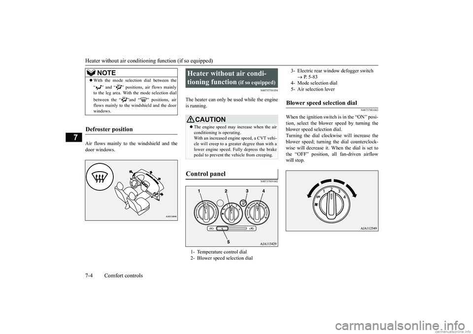
Air flows mainly to the windshield and the door windows.
N00737701054
The heater can only be used while the engineis running.
N00737801042
N00737901043
When the ignition switch is in the “ON” posi- tion, select the blower speed by turning the blower speed selection dial. Turning the dial clockwise will increase the blower speed; turning
the dial counterclock-
wise will decrease it. When the dial is set to the “OFF” position, all fan-driven airflow will stop.
NOTE
With the mode selec
tion dial between the
“ ” and “ ” positions, air flows mainly to the leg area. With the mode selection dial between the “ ”and “ ” positions, air flows mainly to the windshield and the door windows.
Defroster position
Heater without air condi- tioning function
(if so equipped)
CAUTION The engine speed may increase when the air conditioning is operating. With an increased engi
ne speed, a CVT vehi-
cle will creep to a greater degree than with alower engine speed. Fully depress the brake pedal to prevent the vehicle from creeping.
Control panel
1- Temperature control dial 2- Blower speed selection dial
3- Electric rear window
defogger switch
P. 5 - 8 3
4- Mode selection dial5- Air selection leverBlower speed selection dial
BK0249600US.book 4 ページ 2017年4月20日 木曜日 午後1時36分
Page 177 of 263

Heater without air conditioning function (if so equipped) 7-6 Comfort controls
7
N00738301099
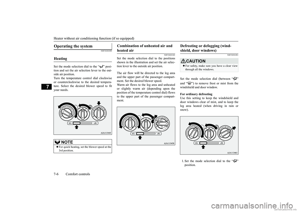
Set the mode selection dial to the “ ” posi- tion and set the air sele
ction lever to the out-
side air position. Turn the temperature control dial clockwise or counterclockwise to
the desired tempera-
ture. Select the desire
d blower speed to fit
your needs.
N00738401045
Set the mode selection
dial to the positions
shown in the illustration and set the air selec- tion lever to the outside air position. The air flow will be directed to the leg area and the upper part of the passenger compart-ment. Set the desired blower speed. Warm air flows to the leg area and unheated or slightly warm air (depending upon the position of the temperat
ure control dial) flows
to the upper part of the passenger compart-ment.
N00738501091
Set the mode selection dial (between “ ” and “ ”) to remove frost or mist from the windshield and door window. For ordinary defrosting Use this setting to ke
ep the windshield and
door windows clear of mist, and to keep the leg area heated (when driving in rain or snow). 1. Set the mode select
ion dial to the “ ”
position.
Operating the system
Heating
NOTE
For quick heating, set the blower speed at the 3rd position.
Combination of unheated air and heated air
Defrosting or defogging (wind-shield, door windows)
CAUTION For safety, make sure you have a clear view through all the windows.
BK0249600US.book 6 ページ 2017年4月20日 木曜日 午後1時36分
Page 178 of 263

Manual air conditioning (if so equipped)
Comfort controls 7-7
7
2. Set the air selection le
ver to the outside air
position.3. Select your desired
blower speed by turn-
ing the blower spee
d selection dial.
4. Select your desired
temperature by turn-
ing the temperature control dial.
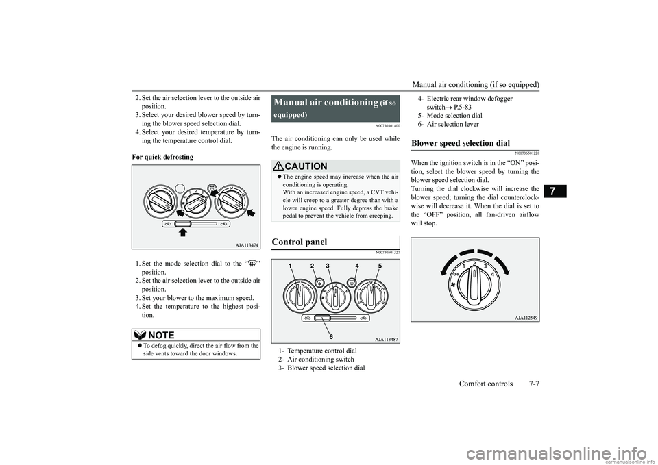
For quick defrosting 1. Set the mode selection dial to the “ ” position. 2. Set the air selection le
ver to the outside air
position. 3. Set your blower to the maximum speed. 4. Set the temperature to the highest posi-tion.
N00730301400
The air conditioning can only be used whilethe engine is running.
N00730501327
N00736501228
When the ignition switch is in the “ON” posi- tion, select the blower speed by turning the blower speed se
lection dial.
Turning the dial clockwise will increase the blower speed; turning
the dial counterclock-
wise will decrease it. When the dial is set to the “OFF” position, all fan-driven airflow will stop.
NOTE
To defog quickly, direct the air flow from the side vents toward the door windows.
Manual air conditioning
(if so
equipped)
CAUTION The engine speed may increase when the air conditioning is operating. With an increased engine speed, a CVT vehi- cle will creep to a greater degree than with alower engine speed. Fully depress the brake pedal to prevent the vehicle from creeping.
Control panel
1- Temperature control dial 2- Air conditioning switch 3- Blower speed selection dial
4- Electric rear
window defogger
switch
P. 5 - 8 3
5- Mode selection dial6- Air selection leverBlower speed selection dial
BK0249600US.book 7 ページ 2017年4月20日 木曜日 午後1時36分
Page 180 of 263

Manual air conditioning (if so equipped)
Comfort controls 7-9
7
N00731001488
Push the switch, and the air conditioning compressor will turn on. The air conditioningindicator light (A) will come on. Push the switch again and the air condition- ing compressor will stop and the indicator light (A) goes off.
N00731101304
Set the mode selection dial to the “ ” posi- tion and set the air sele
ction lever to the out-
side air position. Turn the temperature control dial clockwise or counterclockwise to
the desired tempera-
ture. Select the desire
d blower speed to fit
your needs.
N00731201406
1. Set the mode selection dial to the “ ”position. 2. Set the air selection le
ver to the outside air
position.3. Push the air conditioning switch. 4. Change the temperature by turning the control dial clockwise or counterclock-wise. 5. Set the desired blower speed.
CAUTION Using recirculated ai
r for a long time may
cause the windows to fog up.
Air conditioning switch
Operating the ai
r conditioning
system
Heating
NOTE
For quick heating, set th
e blower speed at the
3rd position.
Cooling
NOTE
If the outside air is dusty or contaminated in some way, set the air selection lever to therecirculation position. Let in some outside air from time to ti
me for good ventilation.
To cool the leg areas,
set the mode selection
dial to the “ ” position.
BK0249600US.book 9 ページ 2017年4月20日 木曜日 午後1時36分
Page 200 of 263

How to change a tire
For emergencies 8-7
8
6. Get the jack, bar and wheel nut wrench ready. (Refer to “Jack and t
ools” on page 8-5.)
N00849600344
The compact spare tire is stowed beneath the floor board of the cargo area. It is designed to save space in the cargo area. Its lighter weightmakes it easier to use if a flat tire occurs.
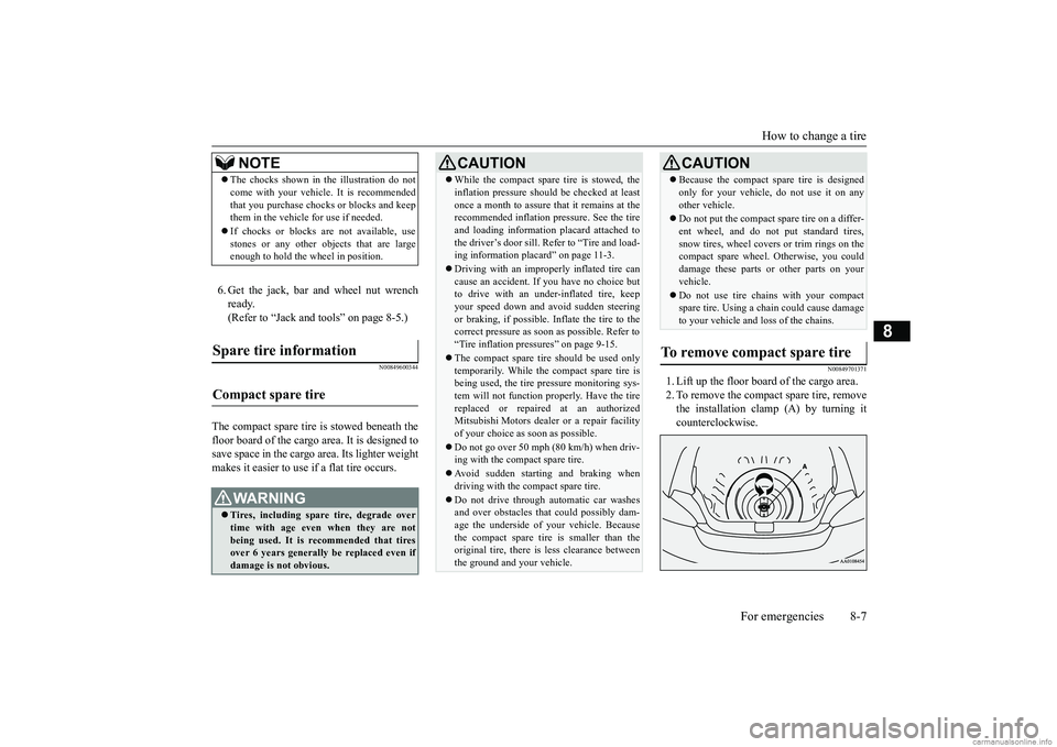
N00849701371
1. Lift up the floor board of the cargo area. 2. To remove the compact spare tire, remove the installation clamp (A) by turning itcounterclockwise.
NOTE
The chocks shown in the illustration do not come with your vehicl
e. It is recommended
that you purchase chocks or blocks and keepthem in the vehicle for use if needed. If chocks or blocks
are not available, use
stones or any other obj
ects that are large
enough to hold the wheel in position.
Spare tire information Compact spare tire
WA R N I N G Tires, including spar
e tire, degrade over
time with age even when they are notbeing used. It is recommended that tires over 6 years generally
be replaced even if
damage is not obvious.
CAUTION While the compact spare tire is stowed, the inflation pressure shoul
d be checked at least
once a month to assure that it remains at therecommended inflation pressure. See the tire and loading informati
on placard attached to
the driver’s door sill. Refer to “Tire and load-ing information placard” on page 11-3. Driving with an imprope
rly inflated tire can
cause an accident. If
you have no choice but
to drive with an under-inflated tire, keep your speed down and av
oid sudden steering
or braking, if possible. Inflate the tire to the correct pressure as soon as possible. Refer to “Tire inflation pressures” on page 9-15. The compact spare tire should be used only temporarily. While th
e compact spare tire is
being used, the tire pr
essure monitoring sys-
tem will not function
properly. Have the tire
replaced or repaired at an authorizedMitsubishi Motors dealer
or a repair facility
of your choice as soon as possible. Do not go over 50 mph (80 km/h) when driv- ing with the compact spare tire. Avoid sudden starting and braking when driving with the compact spare tire. Do not drive through automatic car washes and over obstacles that
could possibly dam-
age the underside of your vehicle. Becausethe compact spare tire is smaller than the original tire, there is less clearance between the ground and your vehicle.
Because the compact spare tire is designed only for your vehicle, do not use it on anyother vehicle. Do not put the compact spare tire on a differ- ent wheel, and do not put standard tires,snow tires, wheel covers
or trim rings on the
compact spare wheel. Otherwise, you could damage these parts or other parts on yourvehicle. Do not use tire chains with your compact spare tire. Using a chain could cause damage to your vehicle and loss of the chains.
To remove compact spare tire
CAUTION
BK0249600US.book 7 ページ 2017年4月20日 木曜日 午後1時36分