brake MITSUBISHI MIRAGE G4 2019 Owner's Manual (in English)
[x] Cancel search | Manufacturer: MITSUBISHI, Model Year: 2019, Model line: MIRAGE G4, Model: MITSUBISHI MIRAGE G4 2019Pages: 267, PDF Size: 38.31 MB
Page 6 of 267
Instruments and controls
Overview 1-2
1
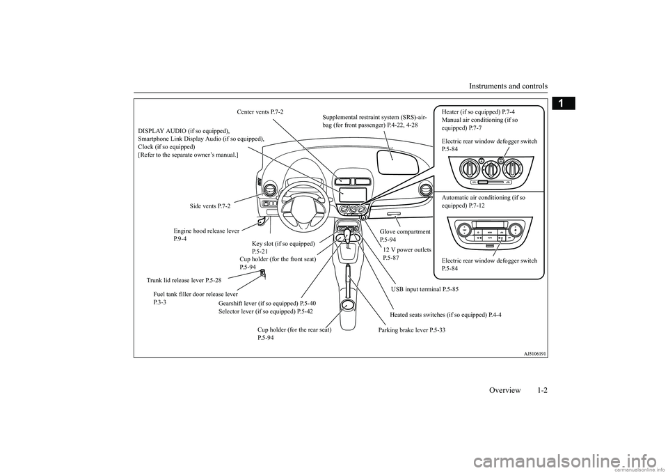
Center vents P.7-2
Supplemental restraint system (SRS)-air- bag (for front passenger) P.4-22, 4-28
Heater (if so equipped) P.7-4 Manual air conditioning (if so equipped) P.7-7 Electric rear window defogger switch P.5-84 Automatic air conditioning (if so equipped) P.7-12
Side vents P.7-2
Glove compartment P.5-94
Engine hood release lever P. 9 - 4
Cup holder (for the front seat) P.5-94
12 V power outlets P.5-87
Electric rear window defogger switch P.5-84
Key slot (if so equipped) P.5-21
Gearshift lever (if so equipped) P.5-40 Selector lever (if so equipped) P.5-42
Fuel tank filler door release lever P. 3 - 3
Parking brake lever P.5-33
Cup holder (for the rear seat) P.5-94
DISPLAY AUDIO (if so equipped), Smartphone Link Display Audio (if so equipped), Clock (if so equipped)[Refer to the separate owner’s manual.]
USB input terminal P.5-85 Heated seats switches (if so equipped) P.4-4
Trunk lid release lever P.5-28
BK0267800US.book 2 ページ 2018年5月30日 水曜日 午後4時24分
Page 13 of 267
If this warning light comes on or flashes while you’re driving... 2-2 Quick index
2
or
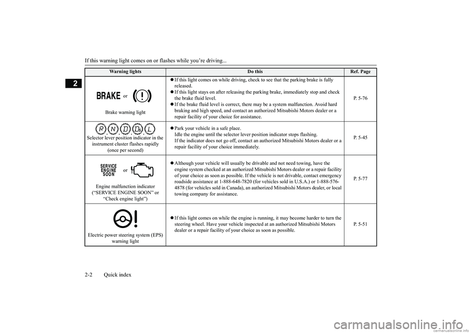
Brake warning light
If this light comes on while driving, chec
k to see that the parking brake is fully
released. If this light stays on after releasing the
parking brake, immediately stop and check
the brake fluid level. If the brake fluid level is correct, there
may be a system malfunction. Avoid hard
braking and high speed, and contact an au
thorized Mitsubishi Motors dealer or a
repair facility of your
choice for assistance.
P. 5-76
Selector lever position indicator in the instrument cluster flashes rapidly
(once per second)
Park your vehicle in a safe place. Idle the engine until the selector le
ver position indicato
r stops flashing.
If the indicator does not go of
f, contact an authorized Mi
tsubishi Motors dealer or a
repair facility of your
choice immediately.
P. 5-45
or
Engine malfunction indicator (“SERVICE ENGINE SOON” or
“Check engine light”)
Although your vehicle will usually be dr
ivable and not need towing, have the
engine system checked at an authorized M
itsubishi Motors dealer
or a repair facility
of your choice as soon as possible. If the
vehicle is not drivab
le, contact emergency
roadside assistance at 1-888-648-7820 (for
vehicles sold in U.S.A.) or 1-888-576-
4878 (for vehicles sold in Canada), an auth
orized Mitsubishi Moto
rs dealer, or local
towing company for assistance.
P. 5-77
Electric power stee
ring system (EPS)
warning light
If this light comes on while the engine is
running, it may become harder to turn the
steering wheel. Have your ve
hicle inspected at an aut
horized Mitsubishi Motors
dealer or a repair facility of
your choice as soon as possible.
P. 5-51
Warning lights
Do this
Ref. Page
BK0267800US.book 2 ページ 2018年5月30日 水曜日 午後4時24分
Page 16 of 267
If this problem occurs...
Quick index 2-5
2
N00200902092
If this problem occurs...
Problem
Do this
Ref. Page
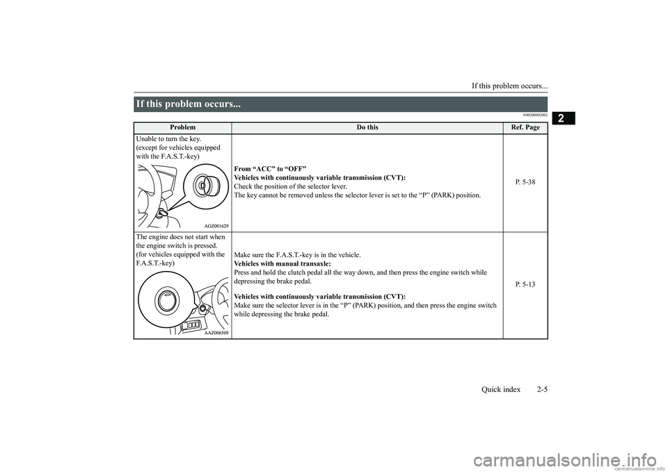
Unable to turn the key. (except for vehicles equipped with the F.A.S.T.-key)
From “ACC” to “OFF” Vehicles with cont
inuously variable
transmission (CVT):
Check the position of the selector lever. The key cannot be removed unless the selector
lever is set to the “P” (PARK) position.
P. 5-38
The engine does not start when the engine switch is pressed. (for vehicles equipped with the F. A . S . T. - k e y )
Make sure the F.A.S.T.-key is in the vehicle. Vehicles with ma
nual transaxle:
Press and hold the clutch pedal all the way dow
n, and then press the
engine switch while
depressing the brake pedal. Vehicles with cont
inuously variable
transmission (CVT):
Make sure the selector lever is in the “P” (P
ARK) position, and then press the engine switch
while depressing the brake pedal.
P. 5-13
BK0267800US.book 5 ページ 2018年5月30日 水曜日 午後4時24分
Page 17 of 267
If this problem occurs... 2-6 Quick index
2
The engine does not start and the operation mode cannot be changed to OFF. (for vehicles equipped with the F.A.S.T.-key)
1. Move the selector le
ver to the “P” (PARK) position, a
nd then change the operation mode
to OFF. (For vehicles with CVT)2. One of the other causes c
ould be low battery voltage.
If this occurs, the keyless entr
y system and the F.A.S.T.-key
operation will also not oper-
ate.Contact an authorized Mitsubishi Motors dealer.
P. 5-14
The F.A.S.T.-key does not oper- ate.(for vehicles equipped with the F. A . S . T. - k e y )
Use the emergency key to lock and unlock the door. Insert the F.A.S.T.-key into the key slot of th
e floor console, and then start the engine or
change the operation mode.
P. 5-19, 5-20
Cannot shift the selector lever from the “P” (PARK) position. (for vehicles with continuously variable transmission (CVT))
Shift the selector lever while pressing the brake pedal. Check that the ignition switch
or the operation mode is in ON.
P. 5-42
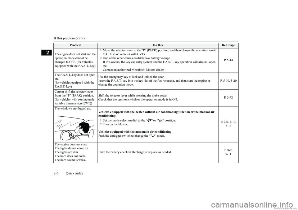
The windows are fogged up.
Vehicles equipped with the he
ater without air conditioning
function or th
e manual air
conditioning
:
1. Set the mode selection dial
to the “ ” or “ ” position.
2. Turn on the blower. Vehicles equipped with th
e automatic air conditioning
:
Push the defogger switch
to change the “ ” mode.
P. 7-6, 7-10,
7-14
The engine does not start. The lights do not come on.The lights are dim. The horn does not honk. The horn sound is weak.
Have the battery checked. Rech
arge or replace as needed.
P. 8-2, 9-11
Problem
Do this
Ref. Page
BK0267800US.book 6 ページ 2018年5月30日 水曜日 午後4時24分
Page 18 of 267
If this problem occurs...
Quick index 2-7
2
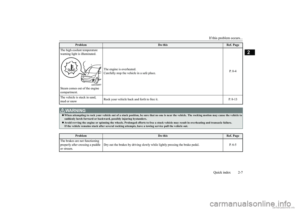
The high coolant temperature warning light is illuminated. Steam comes out of the engine compartment.
The engine is overheated. Carefully stop the vehicle in a safe place.
P. 8 - 4
The vehicle is
stuck in sand,
mud or snow
Rock your vehicle back and forth to free it. P. 8-13
WA R N I N G When attempting to rock your vehicle out of
a stuck position, be sure that
no one is near the vehicl
e. The rocking motion may c
ause the vehicle to
suddenly lurch forward or backward, possibly injuring bystanders. Avoid revving the engine or spin
ning the wheels. Prolonged efforts to free a st
uck vehicle may result in
overheating and transa
xle failure.
If the vehicle remains stuck after several rocking attempts, have a towing service pull the vehicle out.
Problem
Do this
Ref. Page
The brakes are not functioning properly after crossing a puddle or stream.
Dry out the brakes by driving slowly while
lightly pressing the brake pedal. P. 6-5
Problem
Do this
Ref. Page
BK0267800US.book 7 ページ 2018年5月30日 水曜日 午後4時24分
Page 50 of 267
Supplemental Restraint System (SRS) - airbag
Seat and restraint systems 4-23
4
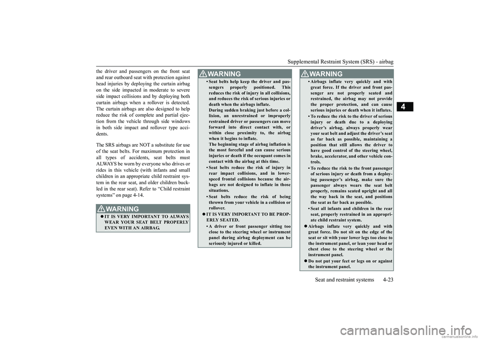
the driver and passengers on the front seat and rear outboard seat
with protection against
head injuries by deploying the curtain airbag on the side impacted
in moderate to severe
side impact collisions
and by deploying both
curtain airbags when a rollover is detected. The curtain airbags are also designed to help reduce the risk of comp
lete and partial ejec-
tion from the vehicle through side windows in both side impact a
nd rollover type acci-
dents. The SRS airbags are NOT a substitute for use of the seat belts. For maximum protection in all types of accidents, seat belts mustALWAYS be worn by everyone who drives or rides in this vehicle
(with infants and small
children in an appropriate child restraint sys-tem in the rear seat, and older children buck- led in the rear seat). Refer to “Child restraint systems” on page 4-14.
WA R N I N G IT IS VERY IMPORTANT TO ALWAYS WEAR YOUR SEAT BELT PROPERLY EVEN WITH AN AIRBAG.
• Seat belts help keep the driver and pas-sengers properly positioned. Thisreduces the risk of injury in all collisions,and reduces the risk of serious injuries or death when the airbags inflate. During sudden braking just before a col-lision, an unrestra
ined or improperly
restrained driver or passengers can move forward into direct contact with, orwithin close proximity to, the airbag when it begins to inflate. The beginning stage of
airbag inflation is
the most forceful and can cause serious injuries or death if the occupant comes in contact with the ai
rbag at this time.
• Seat belts reduce the risk of injury in rear impact collisions, and in lower-speed frontal collisions because the air- bags are not designed
to inflate in those
situations.• Seat belts reduce the risk of beingthrown from your vehi
cle in a collision or
rollover.
IT IS VERY IMPORTANT TO BE PROP- ERLY SEATED.• A driver or front passenger sitting tooclose to the steering wheel or instrument panel during airbag deployment can be seriously inju
red or killed.
WA R N I N G
• Airbags inflate ve
ry quickly and with
great force. If the driver and front pas-senger are not properly seated andrestrained, the airbag may not provide the proper protection, and can cause serious injuries or death when it inflates.• To reduce the risk to the driver of seriousinjury or death
due to a deploying
driver’s airbag, al
ways properly wear
your seat belt and adju
st the driver’s seat
as far back as possible, maintaining aposition that still allows the driver to have good control of the steering wheel, brake, accelerator,
and other vehicle con-
trols.• To reduce the risk to the front passengerof serious injury or
death from a deploy-
ing passenger’s airbag, make sure the passenger always wears the seat beltproperly, remains seat
ed upright and all
the way back in the
seat, and positions
the seat as far back as possible.• Seat all infants and children in the rearseat, properly restrain
ed in an appropri-
ate child restraint system.
Airbags inflate very
quickly and with
great force. Do not sit on the edge of the seat or sit with your
lower legs too close to
the instrument panel,
or lean your head or
chest close to the steering wheel or the instrument panel. Do not put your feet or legs on or against the instrument panel.WA R N I N G
BK0267800US.book 23 ページ 2018年5月30日 水曜日 午後4時24分
Page 53 of 267
Supplemental Restraint System (SRS) - airbag 4-26 Seat and restraint systems
4
N00418600256
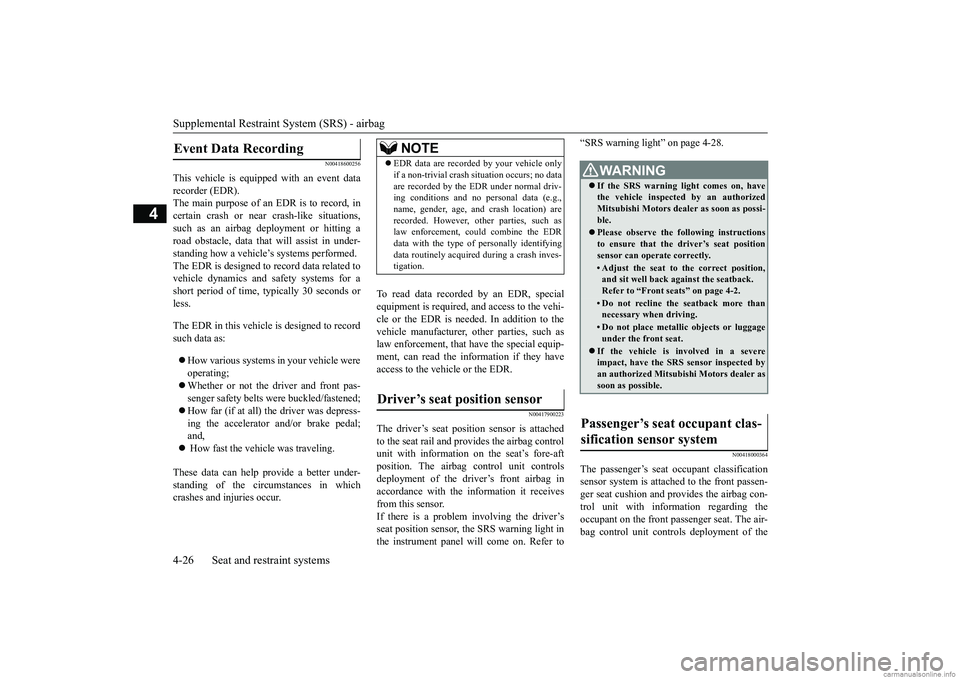
This vehicle is equipped with an event data recorder (EDR). The main purpose of an EDR is to record, incertain crash or near crash-like situations, such as an airbag deployment or hitting a road obstacle, data that
will assist in under-
standing how a vehicle’s systems performed. The EDR is designed to
record data related to
vehicle dynamics and sa
fety systems for a
short period of time,
typically 30 seconds or
less. The EDR in this vehicle is designed to record such data as: How various systems in your vehicle were operating; Whether or not the driver and front pas- senger safety belts
were buckled/fastened;
How far (if at all) the driver was depress- ing the accelerator and/or brake pedal;and, How fast the vehicle was traveling.
These data can help provide a better under- standing of the circumstances in whichcrashes and injuries occur.
To read data recorded
by an EDR, special
equipment is required, a
nd access to the vehi-
cle or the EDR is needed. In addition to the vehicle manufacturer, ot
her parties, such as
law enforcement, that have the special equip-ment, can read the information if they have access to the vehicle or the EDR.
N00417900223
The driver’s seat posit
ion sensor is attached
to the seat rail and provides the airbag control unit with information
on the seat’s fore-aft
position. The airbag control unit controls deployment of the driver’s front airbag in accordance with the information it receivesfrom this sensor. If there is a problem involving the driver’s seat position sensor, th
e SRS warning light in
the instrument panel will come on. Refer to
“SRS warning light” on page 4-28.
N00418000364
The passenger’s seat oc
cupant classification
sensor system is attached to the front passen- ger seat cushion and provides the airbag con- trol unit with inform
ation regarding the
occupant on the front passenger seat. The air- bag control unit controls deployment of the
Event Data Recording
NOTE
EDR data are recorded by your vehicle only if a non-trivial crash situation occurs; no dataare recorded by the EDR under normal driv-ing conditions and no
personal data (e.g.,
name, gender, age, and crash location) are recorded. However, other parties, such aslaw enforcement, could combine the EDR data with the type of personally identifying data routinely acquire
d during a crash inves-
tigation.
Driver’s seat position sensor
WA R N I N G If the SRS warning
light comes on, have
the vehicle inspecte
d by an authorized
Mitsubishi Motors dealer as soon as possi-ble. Please observe the following instructions to ensure that the driver’s seat position sensor can operate correctly.• Adjust the seat to the correct position,and sit well back
against the seatback.
Refer to “Front seats” on page 4-2.• Do not recline the seatback more thannecessary when driving.• Do not place metall
ic objects or luggage
under the front seat.
If the vehicle is involved in a severe impact, have the SRS sensor inspected byan authorized
Mitsubishi Motors dealer as
soon as possible.
Passenger’s seat occupant clas- sification sensor system
BK0267800US.book 26 ページ 2018年5月30日 水曜日 午後4時24分
Page 66 of 267
5
Features and controlsBreak-in recommendations ..............................................................5-2 Keys .................................................................................................5-2 Electronic immobilizer (Anti-theft starting system) ........................5-3Keyless entry system (if so equipped) ..............................................5-6 Free-hand Advanced Security
Transmitter (F.A.S.T.-key)
(if so equipped) ............................................................................5-9Door locks ......................................................................................5-25 Power door locks ......
...........
...........
...........
...........
...........
.........
.....5-26
Child safety locks for rear door ..........
...........
.........
.........
.........
.....5-27
Trunk lid ................
............
...........
...........
...........
...........
...........
.....5-28
Inside emergency trunk lid release ................................................5-29 Manual window control (if so equipped)........................................5-30Power window control ...................................................................5-30 Parking brake .................................................................................5-33 Steering wheel height adjustment ..................................................5-34Inside rearview mirror ...................................................................5-34 Outside rearview mirrors ...............................................................5-36 Ignition switch ...............................................................................5-37Starting the engine .........................................................................5-38 Manual transaxle (if so equipped) ..................................................5-40 Continuously variable transmission
(CVT) (if so equipped)..........5-42
Service brake .................................................................................5-47 Hill start assist ................................................................................5-48 Brake assist system ........................................................................5-49Anti-lock braking system ...............................................................5-50 Electric power steering system (EPS) ............................................5-51 Active stability control (ASC) .......................................................5-52Cruise control (if so equipped) .......................................................5-55
Tire pressure monitoring system (if so equipped) .......................... 5-59 Rear-view camera .......................................................................... 5-62 Instrument cluster .......................................................................... 5-64Multi-information display ............................................................. 5-65 Indicator and warning light package ............................................. 5-75 Indicators ....................................................................................... 5-76Warning lights ................................................................................ 5-76 Combination headlights and dimmer switch ................................. 5-79 Turn signal lever ............................................................................ 5-81Hazard warning flasher switch ...................................................... 5-82 Front fog light switch (if so equipped) .......................................... 5-82 Wiper and washer switch ............................................................... 5-82Electric rear window defogger switch ....
...........
...........
...........
...... 5-84
Horn switch ................................................................................... 5-85 Link System (if so equipped) ......................................................... 5-85USB input terminal ....
...........
...........
...........
...........
...........
............. 5-85
Sun visors ...................................................................................... 5-86 12 V power outlets ......................................................................... 5-87 HomeLink
® Wireless Control System (if so equipped) ................. 5-87
Interior lights ................................................................................. 5-92 Storage spaces ................................................................................ 5-93Cup holders .................................................................................... 5-94 Bottle holders ................................................................................. 5-95 Convenience hook ............
...........
...........
...........
...........
...........
...... 5-95
Assist grips .................................................................................... 5-96
BK0267800US.book 1 ページ 2018年5月30日 水曜日 午後4時24分
Page 79 of 267
Free-hand Advanced
Security Transmitter (F.A.S
.T.-key) (if so equipped)
5-14 Features and controls
5
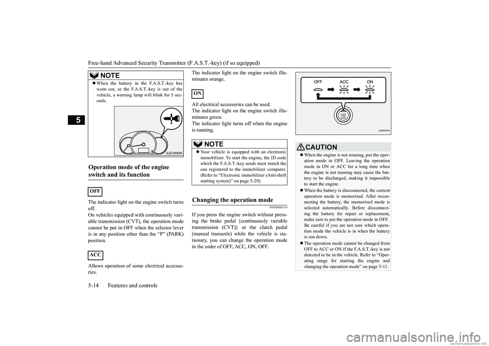
The indicator light on th
e engine switch turns
off.On vehicles equipped
with continuously vari-
able transmission (CVT), the operation mode cannot be put in OFF wh
en the selector lever
is in any position other than the “P” (PARK) position. Allows operation of some electrical accesso- ries.
The indicator light on th
e engine switch illu-
minates orange. All electrical accessories can be used. The indicator light on th
e engine switch illu-
minates green. The indicator light turns off when the engineis running.
N00568001110
If you press the engine
switch without press-
ing the brake pedal {continuously variable transmission (CVT)} or the clutch pedal (manual transaxle) while the vehicle is sta-tionary, you can change the operation mode in the order of OFF, ACC, ON, OFF.
When the battery in the F.A.S.T.-key has worn out, or the F.A.S.T.-key is out of thevehicle, a warning lamp
will blink for 5 sec-
onds.
Operation mode of the engine switch and its function
OFF ACC
NOTE
ON
NOTE
Your vehicle is equippe
d with an electronic
immobilizer. To start the engine, the ID codewhich the F.A.S.T.-key sends must match the one registered to the immobilizer computer. (Refer to “Electronic immobilizer (Anti-theftstarting system)” on page 5-20)
Changing the operation mode
CAUTION When the engine is not running, put the oper- ation mode in OFF. Leaving the operationmode in ON or ACC for a long time when the engine is not r
unning may cause the bat-
tery to be discharged, making it impossibleto start the engine. When the battery is disconnected, the current operation mode is memorized. After recon- necting the battery, the memorized mode is selected auto
matically. Before disconnect-
ing the battery for repair or replacement, make sure to put the
operation mode in OFF.
Be careful if you are not sure which opera-tion mode the vehicle is
in when the battery
is run down. The operation mode cannot be changed from OFF to ACC or ON if the F.A.S.T.-key is not detected to be in the
vehicle. Refer to “Oper-
ating range for starting the engine and changing the operation mode” on page 5-11.
BK0267800US.book 14 ページ 2018年5月30日 水曜日 午後4時24分
Page 82 of 267
Free-hand Advanced Securi
ty Transmitter (F.A.S.T.-key) (if so equipped)
Features and controls 5-17
5
N00514601357
The operation mode can be in any mode to start the engine. The starter motor will be turning for up to approximately 15 seconds if the engine switch is released at once. Pressing the engine switch again while the starter motor is still turning will stop the starter motor. The starter motor will be turningfor up to approximately 30 seconds while the engine switch is pressed. If the engine does not start, wait for awhile and then attempt to start the engine again. Trying repeatedly with the starter motor still turning will damage the startermechanism. If the engine will not
start because the bat-
tery is weak or discharged, refer to“Jump-starting the engine” on page 8-2 for instructions. A longer warm up period will only con- sume extra fuel. The engine is warmed up enough for driv- ing when the low coolant temperatureindicator goes out. Refer to “Low coolant temperature indi- cator” on page 5-76.
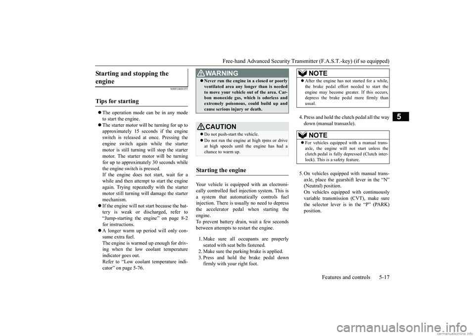
Your vehicle is equipped with an electroni- cally controlled fuel injection system. This is a system that automatically controls fuelinjection. There is usually no need to depress the accelerator pedal when starting the engine.To prevent battery drain, wait a few seconds between attempts to restart the engine. 1. Make sure all occupants are properly seated with seat belts fastened.2. Make sure the parking brake is applied. 3. Press and hold the brake pedal down firmly with your right foot.
4. Press and hold the clut
ch pedal all the way
down (manual transaxle). 5. On vehicles equipped with manual trans- axle, place the gearshift lever in the “N” (Neutral) position.On vehicles equippe
d with continuously
variable transmission (CVT), make sure the selector lever is in the “P” (PARK)position.
Starting and stopping the engine
Tips for starting
WA R N I N G Never run the engine in
a closed or poorly
ventilated area any longer than is neededto move your vehicle
out of the area. Car-
bon monoxide gas, wh
ich is odorless and
extremely poisonous, could build up and cause serious injury or death.CAUTION Do not push-start the vehicle.Do not run the engine at high rpms or drive at high speeds until
the engine has had a
chance to warm up.
Starting the engine
NOTE
After the engine has not started for a while, the brake pedal effort needed to start theengine may become grea
ter. If this occurs,
depress the brake pedal more firmly than usual.NOTE
For vehicles equipped with a manual trans- axle, the engine will
not start unless the
clutch pedal is fully depressed (Clutch inter- lock). This is a safety feature.
BK0267800US.book 17 ページ 2018年5月30日 水曜日 午後4時24分