low fuel MITSUBISHI MIRAGE G4 2019 Owner's Manual (in English)
[x] Cancel search | Manufacturer: MITSUBISHI, Model Year: 2019, Model line: MIRAGE G4, Model: MITSUBISHI MIRAGE G4 2019Pages: 267, PDF Size: 38.31 MB
Page 22 of 267
Filling the fuel tank
General information 3-3
3
Use of gasolines blended with MMT may adversely affect performance, and cause themalfunction indicator on your instrument panel to come on. If this happens, contact an authorized Mitsubishi Motors dealer or arepair facility of your
choice for assistance.
Your vehicle may have
been designed to sat-
isfy California’s low-emission regulations based on clean-burning low-sulfur gasoline.Gasoline sold in parts of the country other than California is allowed to have a higher sulfur content. Using such gasoline couldadversely affect the ve
hicle’s catalytic con-
verter and cause the e
ngine malfunction indi-
cator (“SERVICE ENGINE SOON” or“Check engine light”) to come on. Illumina- tion of this indicator while using high-sulfur gasoline does not necessarily mean the vehi-cle’s emission-control system is malfunction- ing. Your authorized Mitsubishi Motors dealer may suggest usi
ng a different, lower-
sulfur brand of unleaded gasoline to deter- mine if the problem
is fuel-related.
N00301102005
Sulfur in gasoline
NOTE
Poor-quality gasoline
can cause problems
such as hard starting, stalling during idling,abnormal engine noise
, and poor accelera-
tion. If you experience any of these prob- lems, try using a differ
ent brand of gasoline.
If the engine malfunc
tion indicator (“SER-
VICE ENGINE SOON”
or “Check engine
light”) flashes, have
the vehicle inspected as
soon as possible by the nearest authorizedMitsubishi Motors dealer
or a repair facility
of your choice. Repeatedly driving short distances at low speeds can cause deposits to form in the fuel system and engine, resulting in hard startingand poor acceleration.
If these problems
occur, you are advised to add a detergent additive to the gasoline when you refuel thevehicle. The additive
will remove the depos-
its, thereby returning the engine to a normal condition. Be sure to use a MitsubishiMotors Genuine cleani
ng additive. Using an
unsuitable additive c
ould make an engine
malfunction. For details,
please contact the
nearest authorized Mits
ubishi Motors dealer.
Filling the fuel tank
WA R N I N GWhen handling fuel, comply with the safety regulations displayed by garages and filling stations.
Gasoline is highly flammable and explo- sive. You could be burned, seriouslyinjured or killed when handling it. Whenrefueling your vehicle,
always turn the
engine off and keep
away from flames,
sparks, and smoking materials. Alwayshandle fuel in well-ventilated outdoor areas. Before removing the fuel tank filler cap, be sure to get rid of your body’s static electricity by touching a metal part of thecar or fuel pump. Any
static electricity on
your body could create a spark that ignites fuel vapor. Perform the whole
refueling process
(opening the fuel tank filler door, remov-ing the fuel tank filler cap, etc.) by your- self; do not let any other person near the fuel tank filler. If you allowed a person tohelp you and that person was carrying static electricity,
fuel vapor could be
ignited. Do not move away from the fuel tank filler until refueling is fi
nished. If you moved
away and did something
else (for example,
sitting on a seat) part-way through the refueling process, you could pick up afresh charge of st
atic electricity.
Be careful not to inhale fuel vapor. Fuel contains toxic substances. Keep the doors and wi
ndows closed while
refueling the vehicle. If they were open, fuel vapor could get into the cabin.WA R N I N G
BK0267800US.book 3 ページ 2018年5月30日 水曜日 午後4時24分
Page 23 of 267
Filling the fuel tank 3-4 General information
3
9.2 gal (35 L) 1. Before filling with
fuel, stop the engine.
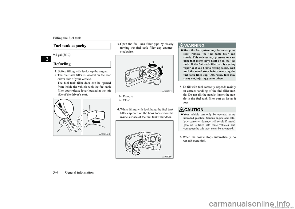
2. The fuel tank filler is located on the reardriver side of your vehicle. The fuel tank filler door can be opened from inside the vehicle with the fuel tank filler door releas
e lever located at the left
side of the driver’s seat.
3. Open the fuel tank filler pipe by slowly turning the fuel tank filler cap counter-clockwise. 4. While filling with fuel, hang the fuel tank filler cap cord on the hook located on theinside surface of the fuel tank filler door.
5. To fill with fuel correctly depends mainly on correct handling of the fuel filler noz- zle. Do not tilt the nozzle. Insert the noz- zle in the fuel tank filler port as far as itgoes. 6. When the nozzle stops automatically, do not add more fuel.
Fuel tank capacity Refueling
1- Remove 2- Close
AJA117951AJA117964
WA R N I N G Since the fuel system may be under pres- sure, remove the fuel tank filler capslowly. This relieves
any pressure or vac-
uum that might have built up in the fuel tank. If the fuel tank filler cap is venting vapor or if you hear
a hissing sound, wait
until the sound stops before removing the fuel tank filler cap. Otherwise, fuel may spray out, injuring you or others.CAUTION Your vehicle can onl
y be operated using
unleaded gasoline. Seri
ous engine and cata-
lytic converter
damage will result if leaded
gasoline is filled into these vehicles, and consequently, this must
never be attempted.
BK0267800US.book 4 ページ 2018年5月30日 水曜日 午後4時24分
Page 24 of 267
Modifications to and racing of your vehicle
General information 3-5
3
7. To close, turn the fuel tank filler cap slowly clockwise un
til you hear clicking
sounds, then gently push the fuel tankfiller door closed.
N00301600194
This vehicle should not be modified withnon-Mitsubishi Motors genuine parts. Mitsubishi Motors designs and manufactures high quality vehicles
with an emphasis on
safety and durability.
Modifications using
non-Mitsubishi Motors genuine parts may affect the performance, safety and/or durabil-ity of your vehicle,
and may violate applica-
ble state and/or fe
deral regulations.
DAMAGE OR PERFORMANCE PROB- LEMS RESULTING FROM MODIFICA-TIONS TO OR RACING OF YOUR
VEHICLE ARE NOT COVERED UNDER WARRANTY. Examples of modifications to your vehicle that can cause damage or performance prob- lems include the following: Failure to use Mits
ubishi Motors genuine
parts Failure to use required fuel and fluids Failure to use proper
size tires and wheels
Modification of the fu
el, intake, exhaust,
emission, suspension,
engine, drive train
or electrical wiring systems Modification of any onboard com- puter/control module, including repro- gramming, or replac
ing/adding chips to
any onboard computer/control module
Review the Warranty
and Maintenance Man-
ual for further details
regarding warranty cov-
erage.
N00301701277
CAUTION To avoid fuel spillage
and overfilling, do not
“top-off” the fuel tank. Spilled fuel coulddiscolor, stain, or cr
ack the vehicle’s paint-
work. If fuel spills on the paintwork, wipe it off with a soft cloth.WA R N I N G Make sure the fuel tank filler cap is securely closed. If the fuel tank filler cap were loose, fuel coul
d leak, resulting in a
fire.CAUTION If you need to replace the fuel tank filler cap, use only the fuel tank filler cap specified for your model vehicle.
NOTE
If the fuel tank filler cap is not tight while driving, the engine
malfunction indicator
(“SERVICE ENGINE SOON” or “Checkengine light”) may come on when the onboard diagnostic (OBD) system performs a self check.Always tighten the fu
el tank filler cap until
you hear at least 3 clicks. The indicator will go of
f after several driving
cycles. If the indicato
r does not go off, con-
tact your authorized
Mitsubishi Motors
dealer or a repair faci
lity of your choice as
soon as possible.
Modifications to and racing of your vehicle
Installation of accessories
CAUTION Before any electrical or electronic accesso- ries are installed,
consult an authorized
Mitsubishi Motors dealer.
BK0267800US.book 5 ページ 2018年5月30日 水曜日 午後4時24分
Page 25 of 267
Genuine Mitsubishi Motors parts 3-6 General information
3
The installation of accessories, optional parts, etc., should only be performed within the limits prescribed by law, and inaccordance with the guidelines and warn- ings contained within the documents accompanying this vehicle.Only Mitsubishi Moto
rs approved acces-
sories should be fitt
ed to your vehicle.
Improper installation of
electrical parts
could cause a fire. Refer to the “Modifica- tion/alterations to the electrical or fuel systems” section with
in this owner’s man-
ual. Using a cellular phone
or radio set inside
the vehicle without an external antennamay cause electrical system interference, which could lead to unsafe vehicle opera- tion. Tires and wheels which do not meet spec- ifications must not be used.
Refer to the “Specifications” section for information regard
ing wheel and tire
sizes.
Due to the large number of accessory and replacement parts provided by different man- ufacturers in the market, it is not always pos- sible for an authorized Mitsubishi Motorsdealer to check whether the attachment or installation of a non-Mi
tsubishi Motors genu-
ine parts affects the driving safety of yourMitsubishi-vehicle.
N00301800183
Mitsubishi Motors manu
factures high quality
vehicles with an emphasis on safety. It isimportant to consult an
authorized Mitsubishi
Motors dealer before
installation of any
accessory which may in
volve modification of
the electrical or fuel systems.
N00301401261
Mitsubishi Motors Genuine Parts are designed and manufactured to meet high stan- dards of performance, and are recommendedfor all of your maintenance needs. Also avail- able from your Mitsubishi Motors dealer are a wide variety of acce
ssories to personalize
your new vehicle. Each Mitsubishi Motors
Your vehicle is equipped with a diagnosis connector (data link connector) for checkingand servicing the elec
tronic control system.
Mitsubishi Motors doe
s not recommend con-
necting a device other th
an the Scan Tool for
inspections and service to this connectorbecause an unexpected
problem could result.
In addition, malfuncti
ons caused by connect-
ing a device other than the Scan Tool maynot be covered under warranty.CAUTION
WA R N I N G While driving, do not use a cellular phone in a way that hinder
s safe driving. Any-
thing, including cell
ular phone usage, that
distracts you from the safe operation of your vehicle incr
eases your risk of an acci-
dent. Refer to and follow al
l state and local laws
in your area regardi
ng cellular phone
usage while driving.
Important point!
Modification/alterations to the electrical or fuel systems
CAUTION Please consult an authorized Mitsubishi Motors dealer concer
ning any such acces-
sory fitment or modification. If the wires interfere
with the vehicle body or
improper installation me
thods are used (pro-
tective fuses not included, etc.), electronic devices may be adversel
y affected, resulting
in a fire, vehicle dama
ge, or other accident.
Genuine Mitsubishi Motors parts
BK0267800US.book 6 ページ 2018年5月30日 水曜日 午後4時24分
Page 67 of 267
Break-in recommendations 5-2 Features and controls
5
N00508701382
Advanced automobile manufacturing tech- niques permit you to operate your new vehi- cle without requiring
a long break-in period
of low-speed driving. However, you can add to the future perfor- mance and economy of your vehicle byobserving the followi
ng precautions during
the first 300 miles (500 km). Drive your vehicle at moderate speeds during the break-in period. Avoid revving the engine. Avoid rough driving such as sudden starts, sudden acceleration, prolonged high- speed driving and sudden braking. These would have a detrimen
tal effect on the
engine and also cause increased fuel and oil consumption, wh
ich could result in
malfunction of the engine components. Beparticularly careful to
avoid full accelera-
tion while in low shift position (low gears). Do not overload the ve
hicle. Stay within
the seating capacity. (Refer to “Cargo load precautions” on page 6-10.) Do not use this vehi
cle for trailer towing.
N00508801703
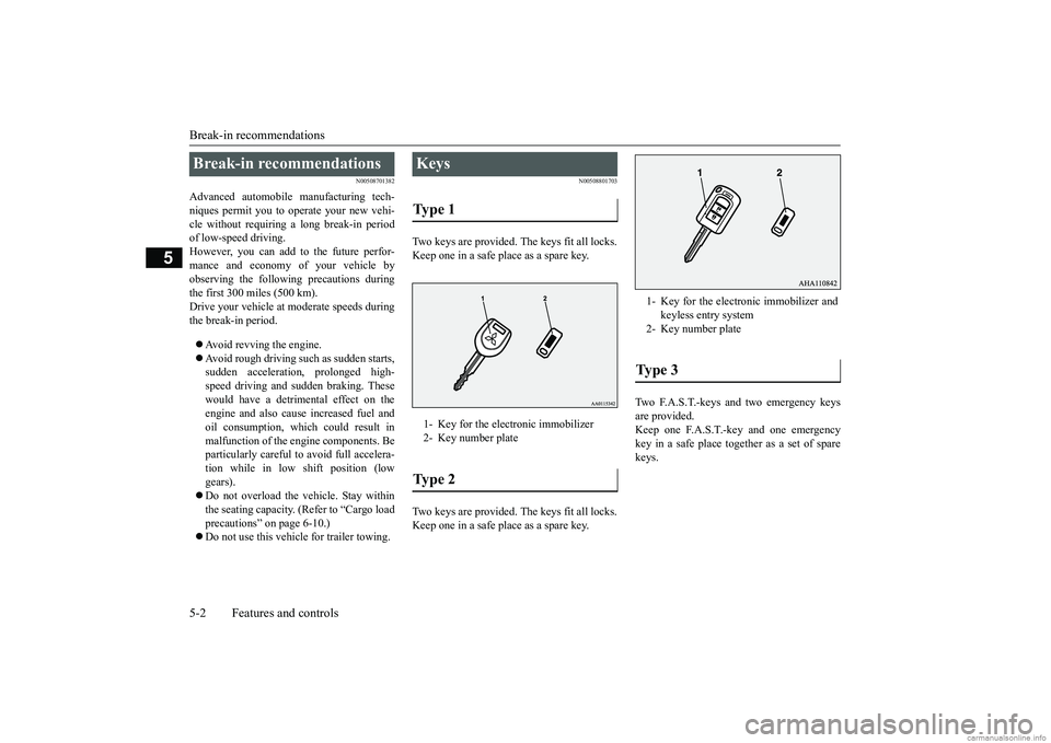
Two keys are provided. The keys fit all locks. Keep one in a safe place as a spare key. Two keys are provided. The keys fit all locks. Keep one in a safe place as a spare key.
Two F.A.S.T.-keys and two emergency keys are provided. Keep one F.A.S.T.-key and one emergency key in a safe place together as a set of sparekeys.
Break-in recommendations
Keys Type 1 1- Key for the electronic immobilizer2- Key number plateType 2
1- Key for the electr
onic immobi
lizer and
keyless entry system
2- Key number plateTy p e 3
BK0267800US.book 2 ページ 2018年5月30日 水曜日 午後4時24分
Page 82 of 267
Free-hand Advanced Securi
ty Transmitter (F.A.S.T.-key) (if so equipped)
Features and controls 5-17
5
N00514601357
The operation mode can be in any mode to start the engine. The starter motor will be turning for up to approximately 15 seconds if the engine switch is released at once. Pressing the engine switch again while the starter motor is still turning will stop the starter motor. The starter motor will be turningfor up to approximately 30 seconds while the engine switch is pressed. If the engine does not start, wait for awhile and then attempt to start the engine again. Trying repeatedly with the starter motor still turning will damage the startermechanism. If the engine will not
start because the bat-
tery is weak or discharged, refer to“Jump-starting the engine” on page 8-2 for instructions. A longer warm up period will only con- sume extra fuel. The engine is warmed up enough for driv- ing when the low coolant temperatureindicator goes out. Refer to “Low coolant temperature indi- cator” on page 5-76.
Your vehicle is equipped with an electroni- cally controlled fuel injection system. This is a system that automatically controls fuelinjection. There is usually no need to depress the accelerator pedal when starting the engine.To prevent battery drain, wait a few seconds between attempts to restart the engine. 1. Make sure all occupants are properly seated with seat belts fastened.2. Make sure the parking brake is applied. 3. Press and hold the brake pedal down firmly with your right foot.
4. Press and hold the clut
ch pedal all the way
down (manual transaxle). 5. On vehicles equipped with manual trans- axle, place the gearshift lever in the “N” (Neutral) position.On vehicles equippe
d with continuously
variable transmission (CVT), make sure the selector lever is in the “P” (PARK)position.
Starting and stopping the engine
Tips for starting
WA R N I N G Never run the engine in
a closed or poorly
ventilated area any longer than is neededto move your vehicle
out of the area. Car-
bon monoxide gas, wh
ich is odorless and
extremely poisonous, could build up and cause serious injury or death.CAUTION Do not push-start the vehicle.Do not run the engine at high rpms or drive at high speeds until
the engine has had a
chance to warm up.
Starting the engine
NOTE
After the engine has not started for a while, the brake pedal effort needed to start theengine may become grea
ter. If this occurs,
depress the brake pedal more firmly than usual.NOTE
For vehicles equipped with a manual trans- axle, the engine will
not start unless the
clutch pedal is fully depressed (Clutch inter- lock). This is a safety feature.
BK0267800US.book 17 ページ 2018年5月30日 水曜日 午後4時24分
Page 103 of 267
Starting the engine 5-38 Features and controls
5
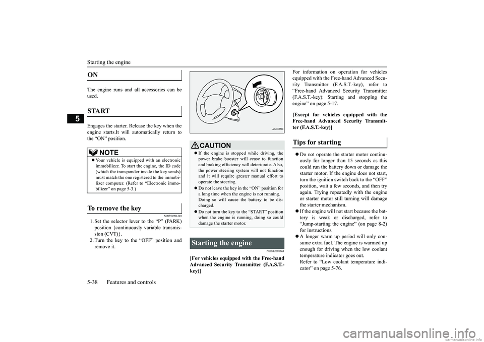
The engine runs and all accessories can be used. Engages the starter. Release the key when the engine starts.It will automatically return to the “ON” position.
N00550901240
1. Set the selector lever to the “P” (PARK)position {continuously variable transmis-sion (CVT)}. 2. Turn the key to the “OFF” position and remove it.
N00512601861
[For vehicles equipped with the Free-hand Advanced Security Tr
ansmitter (F.A.S.T.-
key)]
For information on operation for vehicles equipped with the Free-hand Advanced Secu-rity Transmitter (F.A.S.T.-key), refer to “Free-hand Advanced Se
curity Transmitter
(F.A.S.T.-key): Starting and stopping theengine” on page 5-17. [Except for vehicles equipped with the Free-hand Advanced Security Transmit- ter (F.A.S.T.-key)] Do not operate the starter motor continu- ously for longer than 15 seconds as thiscould run the battery down or damage the starter motor. If the engine does not start, turn the ignition switch back to the “OFF”position, wait a few se
conds, and then try
again. Trying repeatedly with the engine or starter motor still turning will damagethe starter mechanism. If the engine will not start because the bat- tery is weak or discharged, refer to“Jump-starting the engine” (on page 8-2) for instructions. A longer warm up period will only con- sume extra fuel. The engine is warmed up enough for driving when the low coolant temperature indicator goes out.Refer to “Low coolant temperature indi- cator” on page 5-76.
ON START
NOTE
Your vehicle is equippe
d with an electronic
immobilizer. To start
the engine, the ID code
(which the transponder inside the key sends) must match the one regi
stered to the immobi-
lizer computer. (Refer to “Electronic immo- bilizer” on page 5-3.)
To remove the key
CAUTION If the engine is stopped while driving, the power brake booster will cease to functionand braking efficiency will deteriorate. Also, the power steering system will not function and it will require gr
eater manual effort to
operate the steering. Do not leave the key in
the “ON” position for
a long time when the engine is not running. Doing so will cause th
e battery to be dis-
charged. Do not turn the key to the “START” position when the engine is running, doing so coulddamage the starter motor.
Starting the engine
Tips for starting
BK0267800US.book 38 ページ 2018年5月30日 水曜日 午後4時24分
Page 104 of 267
Starting the engine
Features and controls 5-39
5
This model is equipped with an electronically controlled fuel injection system. This is a sys-tem that automatically controls fuel injection. There is usually no need to depress the accel- erator pedal when starting the engine.The starter should not be run for more than 15 seconds at a time. To prevent battery drai
n, wait a few seconds
between attempts to restart the engine. 1. Make sure all occupants are properly seated with seat belts fastened.
2. Insert the ignition key. 3. Make sure the parking brake is applied.4. Press and hold the brake pedal down firmly with your right foot. 5. Press and hold the clutch pedal all the waydown (manual transaxle). 6. On vehicles equippe
d with manual trans-
axle, place the gearshift lever in the “N” (Neutral) position.On vehicles equipped with continuously variable transmission (CVT), make sure the selector lever is in the “P” (PARK)position.
7. Turn the ignition switch to the “ON” posi- tion and make certain that all warninglights are functioning properly before starting the engine. 8. Turn the ignition switch to the “START”position without pressi
ng the accelerator
pedal. Release the
key when the engine
starts.
After several attempts, you may experience that the engine still does not start. 1. Make sure that all electric devices, such as lights, air conditio
ning blower and rear
window defogger, are turned off. 2. While depressing the brake pedal {contin- uously variable transmission (CVT)} orthe clutch pedal (manual transaxle), press the accelerator peda
l halfway and hold it
there, then crank the engine. Release theaccelerator pedal, immediately after the engine starts.
WA R N I N G Never run the engine in
a closed or poorly
ventilated area any lo
nger than is needed
to move your vehicle out of the area. Car-bon monoxide gas, whic
h is odorless and
extremely poisonous, could build up and cause serious injury or death.CAUTION Do not push-start the vehicle.Do not run the engine at high rpms or drive at high speeds until th
e engine has had a
chance to warm up. Release the ignition sw
itch as soon as the
engine starts. Otherwise, the starter motor will be damaged.
Starting the engine
NOTE
On vehicles equipped
with manual transaxle,
the starter will not ope
rate unless the clutch
pedal is fully depresse
d (Clutch interlock).
NOTE
On vehicles equipped
with CVT, the starter
will not operate unless the selector lever is in the “P” (PARK) or “N” (NEUTRAL) posi-tion.For safety reasons, start the engine in the “P” (PARK) position so that the wheels are locked.
NOTE
Minor noises may be heard on engine start- up. These will disappear as the engine warms up.
When the engine is hard to start
BK0267800US.book 39 ページ 2018年5月30日 水曜日 午後4時24分
Page 106 of 267
Manual transaxle (if so equipped)
Features and controls 5-41
5
N00537400065
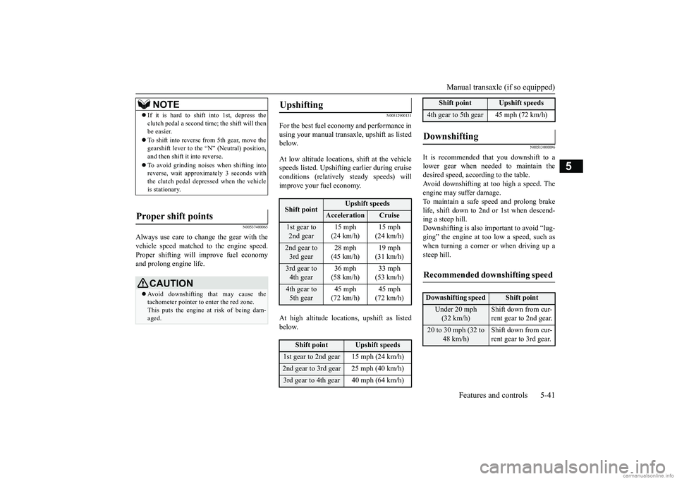
Always use care to cha
nge the gear with the
vehicle speed matched
to the engine speed.
Proper shifting will
improve fuel economy
and prolong engine life.
N00512900131
For the best fuel economy and performance in using your manual transaxle, upshift as listed below. At low altitude locations, shift at the vehicle speeds listed. Upshifting earlier during cruise conditions (relatively
steady speeds) will
improve your fuel economy. At high altitude locati
ons, upshift as listed
below.
N00513000096
It is recommended th
at you downshift to a
lower gear when needed to maintain the desired speed, according to the table. Avoid downshifting at
too high a speed. The
engine may suffer damage. To maintain a safe speed and prolong brake life, shift down to 2nd or 1st when descend-ing a steep hill. Downshifting is also important to avoid “lug- ging” the engine at too low a speed, such as when turning a corner or when driving up a steep hill.
NOTE
If it is hard to shift into 1st, depress the clutch pedal a second time; the shift will thenbe easier. To shift into reverse from 5th gear, move the gearshift lever to the “N” (Neutral) position,and then shift it into reverse. To avoid grinding noises when shifting into reverse, wait approxi
mately 3 seconds with
the clutch pedal depressed when the vehicle is stationary.
Proper shift points
CAUTION Avoid downshifting that may cause the tachometer pointer to enter the red zone. This puts the engine at risk of being dam- aged.
Upshifting
Shift point
Upshift speeds
Acceleration
Cruise
1st gear to 2nd gear
15 mph (24 km/h)
15 mph (24 km/h)
2nd gear to 3rd gear
28 mph (45 km/h)
19 mph (31 km/h)
3rd gear to 4th gear
36 mph (58 km/h)
33 mph (53 km/h)
4th gear to 5th gear
45 mph (72 km/h)
45 mph (72 km/h)
Shift point
Upshift speeds
1st gear to 2nd gear 15 mph (24 km/h)2nd gear to 3rd gear 25 mph (40 km/h)3rd gear to 4th gear 40 mph (64 km/h)
4th gear to 5th gear 45 mph (72 km/h)Downshifting
Recommended downshifting speed
Downshifting speed
Shift point
Under 20 mph (32 km/h)
Shift down from cur- rent gear to 2nd gear.
20 to 30 mph (32 to
48 km/h)
Shift down from cur- rent gear to 3rd gear.
Shift point
Upshift speeds
BK0267800US.book 41 ページ 2018年5月30日 水曜日 午後4時24分
Page 107 of 267
Continuously variable transmission (CVT) (if so equipped) 5-42 Features and controls
5
N00513100244
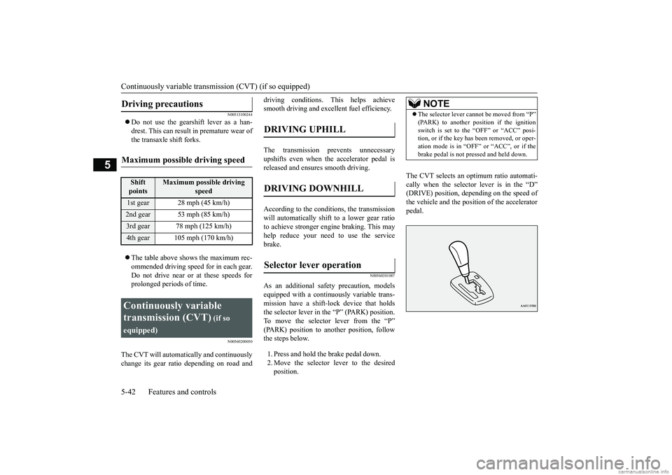
Do not use the gearshift lever as a han- drest. This can result
in premature wear of
the transaxle shift forks. The table above shows the maximum rec- ommended driving speed for in each gear. Do not drive near or at these speeds forprolonged periods of time.
N00560200050
The CVT will automati
cally and continuously
change its gear ratio depending on road and
driving conditions. This helps achieve smooth driving and excellent fuel efficiency. The transmission prevents unnecessary upshifts even when the accelerator pedal isreleased and ensures smooth driving. According to the condi
tions, the transmission
will automatically shift to a lower gear ratio to achieve stronger engi
ne braking. This may
help reduce your need to use the service brake.
N00560301087
As an additional safe
ty precaution, models
equipped with a continuously variable trans- mission have a shift-lock device that holdsthe selector lever in the “P” (PARK) position. To move the selector lever from the “P” (PARK) position to another position, followthe steps below. 1. Press and hold the brake pedal down. 2. Move the selector lever to the desired position.
The CVT selects an optimum ratio automati- cally when the selector lever is in the “D”(DRIVE) position, depending on the speed of the vehicle and the posit
ion of the accelerator
pedal.
Driving precautions
Maximum possible driving speed
Shift points
Maximum possible driving
speed
1st gear 28 mph (45 km/h)2nd gear 53 mph (85 km/h)3rd gear 78 mph (125 km/h)4th gear 105 mph (170 km/h)Continuously variable transmission (CVT)
(if so
equipped)
DRIVING UPHILL
DRIVING DOWNHILL
Selector lever operation
NOTE
The selector lever ca
nnot be moved from “P”
(PARK) to another pos
ition if the ignition
switch is set to the “OFF” or “ACC” posi-tion, or if the key has been removed, or oper- ation mode is in “OFF”
or “ACC”, or if the
brake pedal is not pressed and held down.
BK0267800US.book 42 ページ 2018年5月30日 水曜日 午後4時24分