steering MITSUBISHI MIRAGE G4 2020 (in English) User Guide
[x] Cancel search | Manufacturer: MITSUBISHI, Model Year: 2020, Model line: MIRAGE G4, Model: MITSUBISHI MIRAGE G4 2020Pages: 253, PDF Size: 36.39 MB
Page 66 of 253
5
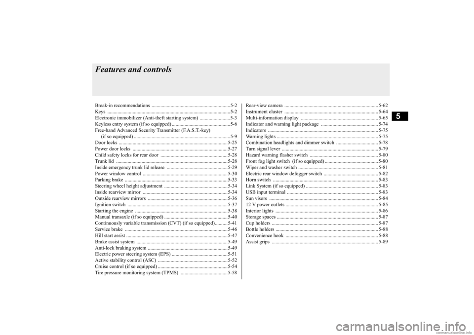
Features and controlsBreak-in recommendations ..............................................................5-2 Keys .................................................................................................5-2 Electronic immobilizer (Anti-theft starting system) ........................5-3Keyless entry system (if so equipped) ..............................................5-6 Free-hand Advanced Security
Transmitter (F.A.S.T.-key)
(if so equipped) ............................................................................5-9Door locks ......................................................................................5-25 Power door locks ......
...........
...........
...........
...........
...........
.........
.....5-27
Child safety locks for rear door ..........
...........
.........
.........
.........
.....5-28
Trunk lid ................
............
...........
...........
...........
...........
...........
.....5-28
Inside emergency trunk lid release ................................................5-29 Power window control ...................................................................5-30Parking brake .................................................................................5-33 Steering wheel height adjustment ..................................................5-34 Inside rearview mirror ...................................................................5-34Outside rearview mirrors ...............................................................5-36 Ignition switch ...............................................................................5-37 Starting the engine .........................................................................5-38Manual transaxle (if so equipped) ..................................................5-40 Continuously variable transmission
(CVT) (if so equipped)..........5-41
Service brake .................................................................................5-46Hill start assist ................................................................................5-47 Brake assist system ........................................................................5-49 Anti-lock braking system ...............................................................5-49Electric power steering system (EPS) ............................................5-51 Active stability control (ASC) .......................................................5-52 Cruise control (if so equipped) .......................................................5-54Tire pressure monitoring system (TPMS) .....................................5-58
Rear-view camera .......................................................................... 5-62 Instrument cluster .......................................................................... 5-64 Multi-information display ............................................................. 5-65Indicator and warning light package ............................................. 5-74 Indicators ....................................................................................... 5-75 Warning lights ................................................................................ 5-75Combination headlights and dimmer switch ................................. 5-78 Turn signal lever ............................................................................ 5-79 Hazard warning flasher switch ...................................................... 5-80Front fog light switch (if so equipped) .......................................... 5-80 Wiper and washer switch ............................................................... 5-81 Electric rear window defogger switch ....
...........
...........
...........
...... 5-82
Horn switch ................................................................................... 5-83 Link System (if so equipped) ......................................................... 5-83 USB input terminal ....
...........
...........
...........
...........
...........
............. 5-83
Sun visors ...................................................................................... 5-84 12 V power outlets ......................................................................... 5-85 Interior lights ................................................................................. 5-86Storage spaces ................................................................................ 5-87 Cup holders .................................................................................... 5-87 Bottle holders ................................................................................. 5-88Convenience hook ............
...........
...........
...........
...........
...........
...... 5-88
Assist grips .................................................................................... 5-89
BK0284300US.book 1 ページ 2019年5月23日 木曜日 午後12時22分
Page 83 of 253
Free-hand Advanced
Security Transmitter (F.A.S
.T.-key) (if so equipped)
5-18 Features and controls
5
2. While depressing the brake pedal {contin- uously variable transmission (CVT)} orthe clutch pedal (manual transaxle), press the accelerator peda
l halfway and hold it
there, then crank th
e engine. Release the
accelerator pedal, immediately after the engine starts. 3. If the engine still will
not start, the engine
could be flooded with too much gasoline. While depressing the brake pedal (CVT) or the clutch pedal (manual transaxle), push the accelerator pedal all the way down and hold it there, then press theengine switch to crank the engine. If the engine does not start
after 5 to 6 seconds,
push the engine switch to stop crankingthe engine, and release the accelerator pedal. Put the opera
tion mode in OFF.
Wait a few seconds, and then press theengine switch to crank the engine again while depressing the brake pedal (CVT) or the clutch pedal (manual transaxle), butdo not push the accelerator pedal. If the engine fails to start, repeat these proce- dures. If the engine stil
l will not start, con-
tact your local Mitsubishi Motors dealer or a repair facility of your choice for assistance.
Startability of continuo
usly variable trans-
mission (CVT) vehicles with an ambient temperature of -4 °F (-20 °C) or lower
When the ambient temperature is -4 °F (-20 °C) or lower, it may not be possible to startfrom a standstill even wi
th the selector lever
in the “D” (DRIVE) or “R” (REVERSE) position.This phenomenon occurs because the trans- axle has not warmed up sufficiently; it does not indicate a problem.
If this occurs, place
the selector lever in the “P” (PARK) position and let the engine idle
for at least 10 minutes.
The transaxle will wa
rm up, and you will be
able to start normally. Do not leave the vehicle during warm-upoperation.
N00568200014
1. Stop the vehicle.2. Fully engage the parking brake while depressing the brake pedal. 3. On vehicles with
a manual transaxle,
press the engine switch to stop the engine, and then move the gearshift lever to the 1st (on a uphill) or “R” (Reverse) (on adownhill) position. On vehicles equippe
d with continuously
variable transmission (CVT), move theselector lever to the “P” (PARK) position, and then press the e
ngine switch to stop
the engine.
Stopping the engine
WA R N I N G Do not operate the en
gine switch while
driving except in an emergency. If the engine is stopped while driving, the brakeservomechanism will ce
ase to function and
braking efficiency will deteriorate. Also, the power steering system will not func-tion and it will require greater manual effort to operate the steering. This could result in a serious accident.
NOTE
If you have to bring the engine to an emer- gency stop while drivi
ng, press and hold the
engine switch for 3 seconds or more, or pressit quickly 3 times or
more. The engine will
stop and the operation mode will go to ACC. On vehicles equipped with continuously variable transmission (CVT), do not stop the engine with the selector
lever in any position
other than the “P” (PARK) position. If the engine is stopped with
the selector lever in
any position other than the “P” (PARK) posi-tion, the operation mode will go to ACC rather than OFF. Put the operation mode
in OFF after placing
the selector lever in the “P” (PARK) posi- tion.
BK0284300US.book 18 ページ 2019年5月23日 木曜日 午後12時22分
Page 99 of 253
Steering wheel height adjustment 5-34 Features and controls
5
N00511500231
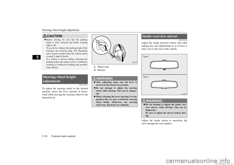
To adjust the steering wheel to the desired position, move the lever upward or down-ward while moving the steering wheel to the desired level.
N00511601486
Adjust the inside rearview mirror only aftermaking any seat adjustme
nts so as to have a
clear view to the rear of the vehicle. Adjust the inside mirror to maximize the view through the rear window.
CAUTION Before driving, be sure that the parking brake is fully released and brake warninglight is off.If you drive without the parking brake fully released, the warning lamp will illuminate and a buzzer sounds when the vehicle speedexceeds 5 mph (8 km/h). If a vehicle is driven without releasing the parking brake, the brakes will be overheated,resulting in ineffectiv
e braking and possible
brake failure.
Steering wheel height adjustment
A- Wheel lock B- ReleaseWA R N I N G After adjusting, make sure the lever is secured in the locked (A) position. Do not attempt to adjust the steering wheel while driving. This can be danger-ous. When releasing the leve
r (moving it to the
position (B)), be sure to hold the steering wheel firmly. Otherwise, the steering wheel may slip down too suddenly.
Inside rearview mirror
WA R N I N G Do not attempt to adjust the inside rear- view mirror while driving. This can bedangerous. Be sure to adjust the mirror before driv- ing.Type 1 Type 2
BK0284300US.book 34 ページ 2019年5月23日 木曜日 午後12時22分
Page 103 of 253
![MITSUBISHI MIRAGE G4 2020 (in English) User Guide Starting the engine 5-38 Features and controls
5
N00512601861
[For vehicles equipped with the Free-hand Advanced Security Transmitter (F.A.S.T.- key)]
For information on
operation for vehicles
equ MITSUBISHI MIRAGE G4 2020 (in English) User Guide Starting the engine 5-38 Features and controls
5
N00512601861
[For vehicles equipped with the Free-hand Advanced Security Transmitter (F.A.S.T.- key)]
For information on
operation for vehicles
equ](/img/19/34857/w960_34857-102.png)
Starting the engine 5-38 Features and controls
5
N00512601861
[For vehicles equipped with the Free-hand Advanced Security Transmitter (F.A.S.T.- key)]
For information on
operation for vehicles
equipped with the Free-hand Advanced Secu-rity Transmitter (F.A
.S.T.-key), refer to
“Free-hand Advanced
Security Transmitter
(F.A.S.T.-key): Starting and stopping theengine” on page 5-16. [Except for vehicles equipped with the Free-hand Advanced Se
curity Transmit-
ter (F.A.S.T.-key)] Do not operate the starter motor continu- ously for longer than 15 seconds as thiscould run the battery
down or damage the
starter motor. If the engine does not start, turn the ignition switch back to the “OFF”position, wait a few se
conds, and then try
again. Trying repeatedly with the engine or starter motor still turning will damagethe starter mechanism. If the engine will not
start because the bat-
tery is weak or discharged, refer to“Jump-starting the engine” (on page 8-2) for instructions. A longer warm up period will only con- sume extra fuel. The engine is warmed up enough for driving when the low coolant temperature indi
cator goes out.
Refer to “Low coolant temperature indi- cator” on page 5-75.
This model is equipped with an electronically controlled fuel injection system. This is a sys-tem that automatically controls fuel injection. There is usually no need to depress the accel- erator pedal when starting the engine.The starter should not be run for more than 15 seconds at a time. To prevent battery drain, wait a few secondsbetween attempts to restart the engine. 1. Make sure all occupants are properly seated with seat belts fastened.
CAUTION If the engine is stopped while driving, the power brake booster will
cease to function
and braking efficiency will deteriorate. Also, the power steering syst
em will not function
and it will require gr
eater manual effort to
operate the steering. Do not leave the key in
the “ON” position for
a long time when the engine is not running. Doing so will cause the battery to be dis- charged. Do not turn the key to the “START” position when the engine is running, doing so coulddamage the starter motor.
Starting the engine
Tips for starting
WA R N I N G Never run the engine in
a closed or poorly
ventilated area any longer than is neededto move your vehicle
out of the area. Car-
bon monoxide gas, wh
ich is odorless and
extremely poisonous, could build up and cause serious injury or death.CAUTION Do not push-start the vehicle.Do not run the engine at high rpms or drive at high speeds until
the engine has had a
chance to warm up. Release the ignition sw
itch as soon as the
engine starts. Otherwis
e, the starter motor
will be damaged.
Starting the engine
BK0284300US.book 38 ページ 2019年5月23日 木曜日 午後12時22分
Page 111 of 253
Service brake 5-46 Features and controls
5
To gain extra acceleration in “D” (DRIVE) position (when passing an
other vehicle) push
the accelerator to the floor. The CVT will automatically downshift.
For short waiting periods, such as at traffic lights, the vehicle can be
left in selector lever
position and held stationary with the servicebrake. For longer waiting periods with the engine running, place th
e selector lever in the “N”
(NEUTRAL) position and apply the parking brake, while holding the vehicle stationary with the service brake. Prior to moving off after having stopped the vehicle, make sure that the selector lever is in“D” (DRIVE) position. To park the vehicle, fi
rst bring it to a com-
plete stop, fully engage the parking brake,
and then move the selector lever to the “P” (PARK) position. If the CVT does not shift while driving, or your vehicle does not pick up enough speed when starting on an uphill slope, it may bethat there is something unusual happening in the transmission. Have your vehicle checked at an authorized Mitsubishi Motors dealer or a repair facility of your choice immediately.
N00517501328
Overuse of the brake can cause weakening,resulting in poor brake response and prema- ture wear of the brake pads.When driving down a long or steep hill, use engine braking by moving
the selector lever
to “Ds” (DOWNSHIFT & SPORTY DRIV-ING) or “L” (LOW) position.
Use the selector lever in the correct shift position in accordance
with driving condi-
tions.Never coast downhill backward in the driv- ing shift position “D” (DRIVE), “Ds” (DOWNSHIFT & SPORTY DRIVING), “L”(LOW) or coast forward in the “R” (REVERSE) position. Engine stopping and in
creased brake pedal
and steering effort could
lead to an accident.
Do not rev the engine
with the brake pedal
pressed when the vehi
cle is stationary.
This can damage the CVT. Also, when you depress
the accelera
tor pedal
while holding down the brake pedal with the selector lever in the “D” (DRIVE) position, the engine revolutions
may not rise as high
as when performing the same operation with the selector lever in the “N” (NEUTRAL) position.
Passing acceleration
CAUTION
Wa i t in g
CAUTION To avoid transmission overheating, never try to keep your vehicle stationary on a hill by using the accelerator
pedal. Always apply
the parking brake and/or service brake. Do not rev the engine unnecessarily while the vehicle is stationary. Unexpected acceler-ation may occur if the se
lector lever is in a
position other than “P” (PARK) or “N” (NEUTRAL).
Parking
When the CVT makes no speed change
Service brake Brake pedal
BK0284300US.book 46 ページ 2019年5月23日 木曜日 午後12時22分
Page 114 of 253
Brake assist system
Features and controls 5-49
5
N00562800092
If an abnormal condition occurs in the sys- tem, the following i
ndicator will turn on.
N00567301116
The brake assist system is a device assisting drivers who cannot depress the brake pedalfirmly such as in em
ergency stop situations
and provides greater braking force.
If the brake pedal is depressed suddenly, the brakes will be applied with more force thanusual.
N00517900338
The anti-lock braking
system helps prevent
the wheels from locking up when braking. This helps maintain vehicle drivability andsteering wheel handling. When using the anti-lock brakes (sudden braking), steering is slightly different from normal driving conditions. Use the steering wheel carefully. Always keep a safe distance from the vehicle in front of you. Even if your vehi- cle is equipped with
the anti-lock braking
system, leave a greater braking distance when: • Driving on gravel or snow-coveredroads. • Driving on uneven road surfaces. Operation of anti-lock braking system is not restricted situations where brakes are applied suddenly. This system may also prevent the wheels from locking whenyou drive over manholes, steel roadwork plates, road markings
, or any uneven road
surface.
Warning indicator
-
ASC indicator
CAUTION If the warning is displayed, the hill start assist will not
operate. Start off carefully.
Park your vehicle in a
safe place and stop the
engine.Restart the engine and check whether the indicator goes out, in wh
ich case the hill start
assist is again working normally. If they remain displayed or reappear fre- quently, it is not necessa
ry to stop the vehicle
immediately, but th
e vehicle should be
inspected by an authorized Mitsubishi Motors dealer or a repair facility of your choice as soon
as possible.
Brake assist system
CAUTIONThe brake assist system is not a device designed to exercise
braking force greater
than its capacity. Make
sure to always keep a
sufficient distance be
tween your vehicle and
a vehicle in front of you without relying toomuch on the brake assist system.NOTE
Once the brake assist system is operational, it maintains great braking force even if the brake pedal is lightly released.To stop its operation, completely remove your foot from the brake pedal. When the brake assist system is in use while driving, you may feel as if the depressed brake pedal is soft, the pedal moves in smallmotions in conjunction with the operation noise, or the vehicle body and the steering wheel vibrate. This occurs when the brakeassist system is ope
rating normally and does
not indicate faulty
operation. Continue to
depress the brake pedal. When the anti-lock brake system warning light is illuminated, th
e brake assist system is
not functioning.
Anti-lock braking system Driving hints
BK0284300US.book 49 ページ 2019年5月23日 木曜日 午後12時22分
Page 116 of 253
Electric power steering system (EPS)
Features and controls 5-51
5
The anti-lock braking system and brake force distribution function ma
y not work, so hard
braking could make the vehicle unstable. Avoid hard braking and high-speed driving.Stop the vehicle in a safe place and contact an authorized MITSUBISHI MOTORS dealer or repair facility
of your choice.
N00529200080
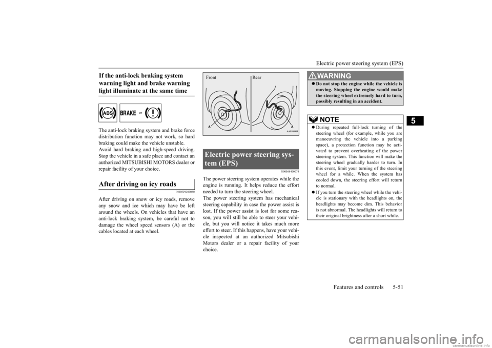
After driving on snow or icy roads, remove any snow and ice which may have be leftaround the wheels. On vehicles that have an anti-lock braking syst
em, be careful not to
damage the wheel spee
d sensors (A) or the
cables located at each wheel.
N00568400074
The power steering system operates while theengine is running. It helps reduce the effort needed to turn the steering wheel. The power steering sy
stem has mechanical
steering capability in case the power assist is lost. If the power assist is lost for some rea- son, you will still be able to steer your vehi-cle, but you will notice it takes much more effort to steer. If this happens, have your vehi- cle inspected at an authorized MitsubishiMotors dealer or a repair facility of your choice.
If the anti-lock braking system warning light and brake warning light illuminate at the same time After driving on icy roads
Electric power steering sys- tem (EPS) Front Rear
WA R N I N G Do not stop the engine while the vehicle is moving. Stopping the engine would makethe steering wheel extremely hard to turn,possibly resulting
in an accident.
NOTE
During repeated full-lock turning of the steering wheel (for example, while you are manoeuvring the vehicle into a parkingspace), a protection f
unction may be acti-
vated to prevent overheating of the power steering system. This f
unction will make the
steering wheel graduall
y harder to turn. In
this event, limit your turning of the steering wheel for a while. When the system hascooled down, the steering effort will return to normal. If you turn the steering wheel while the vehi- cle is stationary with the headlights on, the headlights may become
dim. This behavior
is not abnormal. The he
adlights will return to
their original brightness after a short while.
BK0284300US.book 51 ページ 2019年5月23日 木曜日 午後12時22分
Page 117 of 253
Active stability control (ASC) 5-52 Features and controls
5
If there is a malfunction in the system, the warning light will come on. Under normal conditions, the warning lamp comes on when the ignition switch is turnedto the “ON” position or the operation mode is put in ON, and goes off after the engine has started.
N00559100176
The Active stability control (ASC) takes overall control of the anti-lock braking sys- tem, traction control function and skid controlfunction to help maintain
the vehicle’s control
and traction. Please read
this section in con-
junction with the page on the anti-lock brak-ing system, traction c
ontrol function and skid
control function. Anti-lock braking system
P.5-49
Traction control function
P.5-52
Skid control function
P.5-53
N00559200076
On slippery surfaces, the traction control function prevents the drive wheels from spin-
Electric power steering system warning light
CAUTION If the warning light appears while the engine is running, have the vehicle inspected by an authorized Mitsubishi Motors dealer or arepair facility of your
choice as soon as pos-
sible. It may become ha
rder to turn the steer-
ing wheel.
Active stability control (ASC)
CAUTION Do not over-rely on the ASC. Even the ASC cannot prevent the natural laws of physicsfrom acting on the vehicle. This system, like any other system, has
limits and cannot help
you to maintain traction and control of thevehicle in all circumstances. Reckless driv- ing can lead to accident
s. It is the driver’s
responsibillty to drive carefully, This meanstaking into account the traffic, road and envi- ronmental conditions. Be sure to use the same specified type and size of tire on all four
wheels. Otherwise, the
ASC may not work properly.
Do not install any aftermarket limited slip differential (LSD) on
your vehicle. The ASC
may stop functioning properly.NOTE
An operating sound or vibration may be emitted from under the body in the followingsituations. The sound or vibration is associ- ated with checking th
e operations of the
ASC. At this time,
you may feel a shock
from under the body and the brake pedal if you depress it. These do
not indicate a mal-
function. • When the ignition switch is turned to the “ON” position or the
operation mode is put
in ON. • When the vehicle is driven for a while after the engine is turned on.
When the ASC is acti
vated, you may feel a
vibration in the vehicl
e body or hear a whin-
ing sound from the engine compartment. This indicates that th
e system is operating
normally. It does not i
ndicate a malfunction.
When the anti-lock braking system warning light is illuminated, the ASC is not active.
Traction control function
CAUTION
BK0284300US.book 52 ページ 2019年5月23日 木曜日 午後12時22分
Page 118 of 253
Active stability control (ASC) Features and controls 5-53
5
ning excessive, thus
helping the vehicle to
start moving from a stopped condition. It alsoprovides sufficient driving force and steering performance as the vehicle turns while press- ing the acceleration pedal.
N00559300051
The skid control function is designed to helpthe driver maintain control of the vehicle onslippery roads or during rapid steering maneuvers. It works by
controlling the engine
output and the brake on each wheel.
N00559400254
The ASC is automatically activated when theignition switch is turn
ed to the “ON” position
or the operation mode is put in ON. You can
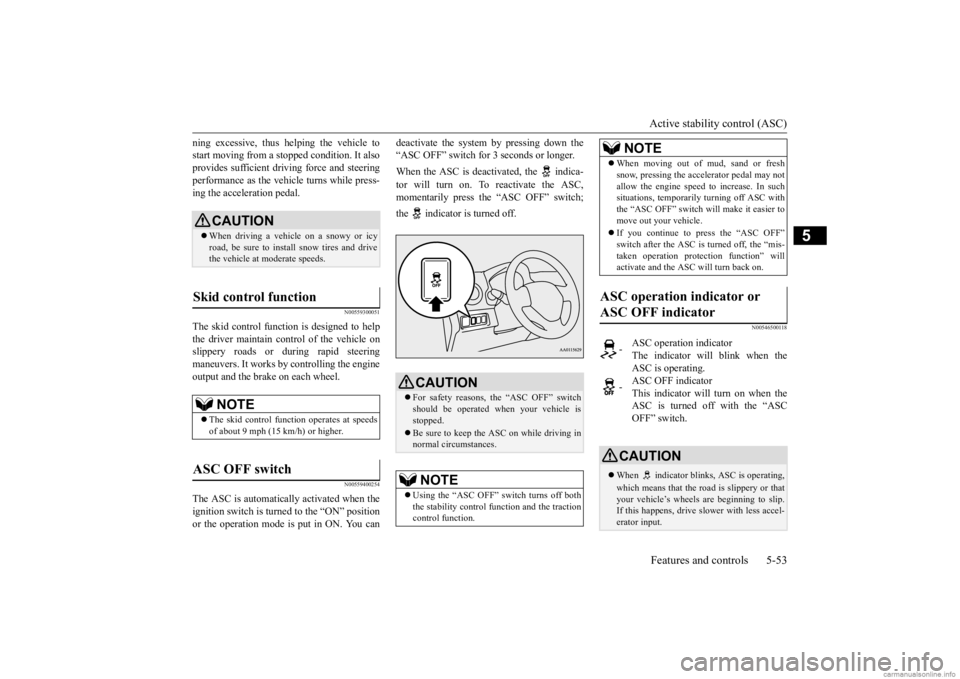
deactivate the system by pressing down the “ASC OFF” switch for
3 seconds or longer.
When the ASC is deacti
vated, the indica-
tor will turn on. To reactivate the ASC, momentarily press the “ASC OFF” switch; the indicator is turned off.
N00546500118
CAUTION When driving a vehicle on a snowy or icy road, be sure to install snow tires and drive the vehicle at moderate speeds.
Skid control function
NOTE
The skid control func
tion operates
at speeds
of about 9 mph (15 km/h) or higher.
ASC OFF switch
CAUTION For safety reasons, the “ASC OFF” switch should be operated when your vehicle isstopped. Be sure to keep the ASC on while driving in normal circumstances.NOTE
Using the “ASC OFF” switch turns off both the stability control f
unction and the traction
control function.
When moving out of mud, sand or fresh snow, pressing the ac
celerator pedal may not
allow the engine speed to increase. In suchsituations, temporaril
y turning off ASC with
the “ASC OFF” switch will make it easier to move out your vehicle. If you continue to press the “ASC OFF” switch after the ASC is turned off, the “mis-taken operation protec
tion function” will
activate and the ASC will turn back on.
ASC operation indicator or ASC OFF indicator
-
ASC operation indicator The indicator will blink when the ASC is operating.
-
ASC OFF indicator This indicator will turn on when the ASC is turned off with the “ASCOFF” switch.
CAUTION When indicator bli
nks, ASC is operating,
which means that the road is slippery or that your vehicle’s wheels are beginning to slip. If this happens, drive slower with less accel-erator input.NOTE
BK0284300US.book 53 ページ 2019年5月23日 木曜日 午後12時22分
Page 125 of 253

Tire pressure monitoring system (TPMS) 5-60 Features and controls
5
Each tire, including the spare, should be checked monthly when cold and inflated tothe inflation pressure recommended by the vehicle manufac
turer on the vehicle placard
or tire inflation pressu
re label. (If your vehi-
cle has tires of a different size than the size indicated on the vehicle
placard or tire infla-
tion pressure label, yo
u should determine the
proper tire inflation pr
essure for those tires.)
As an added safety feature, your vehicle has been equipped with a tire pressure monitoring system (TPMS) that illuminates a low tire pressure telltale when
one or more of your
tires is significant
ly under-inflated.
Accordingly, when the low tire pressure tell- tale illuminates, you should stop and checkyour tires as soon as possible, and inflate them to the proper pressure. Driving on a sig- nificantly under-inflated
tire causes the tire to
overheat and can lead
to tire failure.
Under-inflation also reduces fuel efficiency and tire tread life, and may affect the vehi-cle’s handling and stopping ability. Please note that the TPMS is not a substitute for proper tire maintenance, and it is the driver’sresponsibility to mainta
in correct tire pres-
sure, even if under-inf
lation has not
reached
the level to trigger illumination of the TPMSlow tire pressure telltale. Your vehicle has also been equipped with a TPMS malfunction indicator to indicate when
the system is not operating properly. The TPMS malfunction indicator is combinedwith the low tire pressure telltale. When the system detects a malfunction, the telltale will flash for approximately one min-ute and then remain c
ontinuously illuminated.
This sequence will c
ontinue upon subsequent
vehicle start-ups as long as the malfunctionexists. When the malfunction indicator is illumi- nated, the system may not
be able to detect or
signal low tire pr
essure as intended.
TPMS malfunctions may
occur for a variety
of reasons, including the installation of replacement or alternate tires or wheels on the vehicle that prevent the TPMS from function-ing properly. Always
check the TPMS mal-
function telltale after replacing one or more tires or wheels on your vehicle to ensure thatthe replacement or alternate tires and wheels allow the TPMS to continue to function prop- erly.
N00532801612
1. If the tire pressure monitoring systemwarning light illum
inates, avoid hard
braking, sharp steering maneuvers and high speeds. You should stop and adjust the tires to the proper inflation pressure assoon as possible. Adjust the spare tire at the same time. Refer to “Tires” on page 9-12.
If the warning light illuminates while driving
NOTE
When inspecting or adjusting the tire pres- sure, do not apply excessive force to the valve stem to
avoid breakage.
After inspecting or adjusting the tire pres- sure, always reinstall the valve cap on thevalve stem. Without the valve cap, di
rt or moisture could
get into the valve, resulting in damage to thetire inflation pressure sensor. Do not use metal valve caps, which may cause a metal reaction,
resulting in corrosion
and damage of the tire
inflation pressure sen-
sors. Once adjustments have
been made, the warn-
ing light will go off after a few minutes ofdriving.
BK0284300US.book 60 ページ 2019年5月23日 木曜日 午後12時22分