tire size MITSUBISHI MIRAGE G4 2020 Owner's Manual (in English)
[x] Cancel search | Manufacturer: MITSUBISHI, Model Year: 2020, Model line: MIRAGE G4, Model: MITSUBISHI MIRAGE G4 2020Pages: 253, PDF Size: 36.39 MB
Page 10 of 253
Outside
Overview 1-6
1
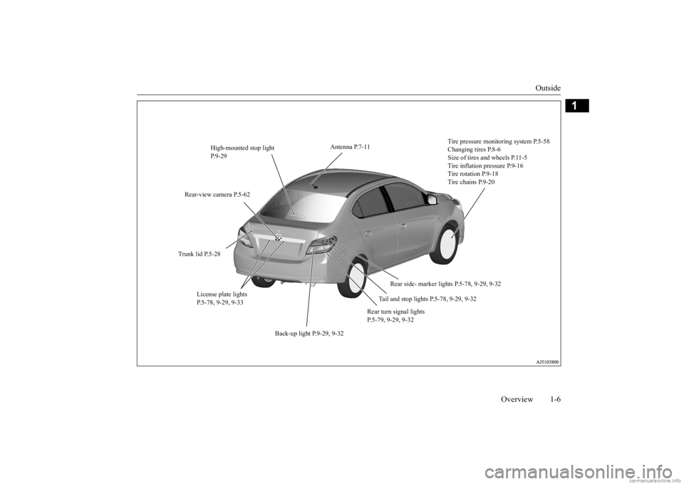
High-mounted stop light P.9-29
Tire pressure monitoring system P.5-58 Changing tires P.8-6 Size of tires and wheels P.11-5Tire inflation pressure P.9-16 Tire rotation P.9-18 Tire chains P.9-20
Trunk lid P.5-28
Tail and stop lights P.5-78, 9-29, 9-32
Rear-view camera P.5-62
Rear turn signal lights P.5-79, 9-29, 9-32
License plate lights P.5-78, 9-29, 9-33
Back-up light P.9-29, 9-32
Antenna P.7-11
Rear side- marker lights P.5-78, 9-29, 9-32
BK0284300US.book 6 ページ 2019年5月23日 木曜日 午後12時22分
Page 24 of 253
Modifications to and racing of your vehicle
General information 3-5
3
7. To close, turn the fuel tank filler cap slowly clockwise un
til you hear clicking
sounds, then gently push the fuel tankfiller door closed.
N00301600194
This vehicle should not be modified withnon-Mitsubishi Motors genuine parts. Mitsubishi Motors designs and manufactures high quality vehicles
with an emphasis on
safety and durability.
Modifications using
non-Mitsubishi Motors genuine parts may affect the performance, safety and/or durabil-ity of your vehicle,
and may violate applica-
ble state and/or fe
deral regulations.
DAMAGE OR PERFORMANCE PROB- LEMS RESULTING FROM MODIFICA-TIONS TO OR RACING OF YOUR
VEHICLE ARE NOT COVERED UNDER WARRANTY. Examples of modifications to your vehicle that can cause damage or performance prob- lems include the following: Failure to use Mits
ubishi Motors genuine
parts Failure to use required fuel and fluids Failure to use proper
size tires and wheels
Modification of the fu
el, intake, exhaust,
emission, suspension,
engine, drive train
or electrical wiring systems Modification of any onboard com- puter/control module, including repro- gramming, or replac
ing/adding chips to
any onboard computer/control module
Review the Warranty
and Maintenance Man-
ual for further details
regarding warranty cov-
erage.
N00301701277
CAUTION To avoid fuel spillage
and overfilling, do not
“top-off” the fuel tank. Spilled fuel coulddiscolor, stain, or cr
ack the vehicle’s paint-
work. If fuel spills on the paintwork, wipe it off with a soft cloth.WA R N I N G Make sure the fuel tank filler cap is securely closed. If the fuel tank filler cap were loose, fuel coul
d leak, resulting in a
fire.CAUTION If you need to replace the fuel tank filler cap, use only the fuel tank filler cap specified for your model vehicle.
NOTE
If the fuel tank filler cap is not tight while driving, the engine
malfunction indicator
(“SERVICE ENGINE SOON” or “Checkengine light”) may come on when the onboard diagnostic (OBD) system performs a self check.Always tighten the fu
el tank filler cap until
you hear at least 3 clicks. The indicator will go of
f after several driving
cycles. If the indicato
r does not go off, con-
tact your authorized
Mitsubishi Motors
dealer or a repair faci
lity of your choice as
soon as possible.
Modifications to and racing of your vehicle
Installation of accessories
CAUTION Before any electrical or electronic accesso- ries are installed,
consult an authorized
Mitsubishi Motors dealer.
BK0284300US.book 5 ページ 2019年5月23日 木曜日 午後12時22分
Page 25 of 253
Genuine Mitsubishi Motors parts 3-6 General information
3
The installation of accessories, optional parts, etc., should only be performed within the limits prescribed by law, and inaccordance with the guidelines and warn- ings contained within the documents accompanying this vehicle.Only Mitsubishi Moto
rs approved acces-
sories should be fitt
ed to your vehicle.
Improper installation of
electrical parts
could cause a fire. Refer to the “Modifica- tion/alterations to the electrical or fuel systems” section with
in this owner’s man-
ual. Using a cellular phone
or radio set inside
the vehicle without an external antennamay cause electrical system interference, which could lead to unsafe vehicle opera- tion. Tires and wheels which do not meet spec- ifications must not be used.
Refer to the “Specifications” section for information regard
ing wheel and tire
sizes.
Due to the large number of accessory and replacement parts provided by different man- ufacturers in the market, it is not always pos- sible for an authorized Mitsubishi Motorsdealer to check whether the attachment or installation of a non-Mi
tsubishi Motors genu-
ine parts affects the driving safety of yourMitsubishi-vehicle.
N00301800183
Mitsubishi Motors manu
factures high quality
vehicles with an emphasis on safety. It isimportant to consult an
authorized Mitsubishi
Motors dealer before
installation of any
accessory which may in
volve modification of
the electrical or fuel systems.
N00301401261
Mitsubishi Motors Genuine Parts are designed and manufactured to meet high stan- dards of performance, and are recommendedfor all of your maintenance needs. Also avail- able from your Mitsubishi Motors dealer are a wide variety of acce
ssories to personalize
your new vehicle. Each Mitsubishi Motors
Your vehicle is equipped with a diagnosis connector (data link connector) for checkingand servicing the elec
tronic control system.
Mitsubishi Motors doe
s not recommend con-
necting a device other th
an the Scan Tool for
inspections and service to this connectorbecause an unexpected
problem could result.
In addition, malfuncti
ons caused by connect-
ing a device other than the Scan Tool maynot be covered under warranty.CAUTION
WA R N I N G While driving, do not use a cellular phone in a way that hinder
s safe driving. Any-
thing, including cell
ular phone usage, that
distracts you from the safe operation of your vehicle incr
eases your risk of an acci-
dent. Refer to and follow al
l state and local laws
in your area regardi
ng cellular phone
usage while driving.
Important point!
Modification/alterations to the electrical or fuel systems
CAUTION Please consult an authorized Mitsubishi Motors dealer concer
ning any such acces-
sory fitment or modification. If the wires interfere
with the vehicle body or
improper installation me
thods are used (pro-
tective fuses not included, etc.), electronic devices may be adversel
y affected, resulting
in a fire, vehicle dama
ge, or other accident.
Genuine Mitsubishi Motors parts
BK0284300US.book 6 ページ 2019年5月23日 木曜日 午後12時22分
Page 115 of 253
Anti-lock braking system 5-50 Features and controls
5
When the anti-lock braking system is in use, you may feel the brake pedal vibrat-ing and hear a unique
sound. It may also
feel as if the pedal
resists being pressed.
In this situation, simply hold the brakepedal down firmly. Do not pump the brake, which will result in reduced braking performance.
N00531600674
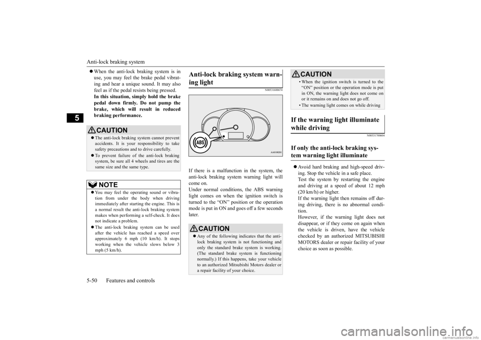
If there is a malfunction in the system, the anti-lock braking system warning light will come on.Under normal conditions, the ABS warning light comes on when the ignition switch is turned to the “ON” position or the operationmode is put in ON and goes off a few seconds later.
N00531700604
Avoid hard braking and high-speed driv- ing. Stop the vehicle in a safe place.Test the system by restarting the engine and driving at a speed of about 12 mph (20 km/h) or higher.If the warning light then remains off dur- ing driving, there is no abnormal condi- tion.However, if the warning light does not disappear, or if they come on again when the vehicle is driven, have the vehiclechecked by an authorized MITSUBISHI MOTORS dealer or re
pair facility of your
choice as soon
as possible.
CAUTIONThe anti-lock braking system cannot prevent accidents. It is your responsibility to take safety precautions a
nd to drive carefully.
To prevent failure of the anti-lock braking system, be sure all 4 wheels and tires are the same size and the same type.NOTE
You may feel the ope
rating sound or vibra-
tion from under the body when driving immediately after starti
ng the engine. This is
a normal result the anti-lock braking systemmakes when performing a self-check. It does not indicate a problem. The anti-lock braking system can be used after the vehicle has
reached a speed over
approximately 6 mph (10 km/h). It stops working when the vehicle slows below 3mph (5 km/h).
Anti-lock braking system warn- ing light
CAUTION Any of the following i
ndicates that the anti-
lock braking system is not functioning andonly the standard brake system is working. (The standard brake system is functioning normally.) If this happens, take your vehicleto an authorized Mitsubishi Motors dealer or a repair facility
of your choice.
• When the ignition switch is turned to the “ON” position or the
operation mode is put
in ON, the warning light does not come onor it remains on and does not go off.• The warning light comes on while driving
If the warning light illuminate while driving If only the anti-lock braking sys- tem warning light illuminate
CAUTION
BK0284300US.book 50 ページ 2019年5月23日 木曜日 午後12時22分
Page 117 of 253
Active stability control (ASC) 5-52 Features and controls
5
If there is a malfunction in the system, the warning light will come on. Under normal conditions, the warning lamp comes on when the ignition switch is turnedto the “ON” position or the operation mode is put in ON, and goes off after the engine has started.
N00559100176
The Active stability control (ASC) takes overall control of the anti-lock braking sys- tem, traction control function and skid controlfunction to help maintain
the vehicle’s control
and traction. Please read
this section in con-
junction with the page on the anti-lock brak-ing system, traction c
ontrol function and skid
control function. Anti-lock braking system
P.5-49
Traction control function
P.5-52
Skid control function
P.5-53
N00559200076
On slippery surfaces, the traction control function prevents the drive wheels from spin-
Electric power steering system warning light
CAUTION If the warning light appears while the engine is running, have the vehicle inspected by an authorized Mitsubishi Motors dealer or arepair facility of your
choice as soon as pos-
sible. It may become ha
rder to turn the steer-
ing wheel.
Active stability control (ASC)
CAUTION Do not over-rely on the ASC. Even the ASC cannot prevent the natural laws of physicsfrom acting on the vehicle. This system, like any other system, has
limits and cannot help
you to maintain traction and control of thevehicle in all circumstances. Reckless driv- ing can lead to accident
s. It is the driver’s
responsibillty to drive carefully, This meanstaking into account the traffic, road and envi- ronmental conditions. Be sure to use the same specified type and size of tire on all four
wheels. Otherwise, the
ASC may not work properly.
Do not install any aftermarket limited slip differential (LSD) on
your vehicle. The ASC
may stop functioning properly.NOTE
An operating sound or vibration may be emitted from under the body in the followingsituations. The sound or vibration is associ- ated with checking th
e operations of the
ASC. At this time,
you may feel a shock
from under the body and the brake pedal if you depress it. These do
not indicate a mal-
function. • When the ignition switch is turned to the “ON” position or the
operation mode is put
in ON. • When the vehicle is driven for a while after the engine is turned on.
When the ASC is acti
vated, you may feel a
vibration in the vehicl
e body or hear a whin-
ing sound from the engine compartment. This indicates that th
e system is operating
normally. It does not i
ndicate a malfunction.
When the anti-lock braking system warning light is illuminated, the ASC is not active.
Traction control function
CAUTION
BK0284300US.book 52 ページ 2019年5月23日 木曜日 午後12時22分
Page 125 of 253

Tire pressure monitoring system (TPMS) 5-60 Features and controls
5
Each tire, including the spare, should be checked monthly when cold and inflated tothe inflation pressure recommended by the vehicle manufac
turer on the vehicle placard
or tire inflation pressu
re label. (If your vehi-
cle has tires of a different size than the size indicated on the vehicle
placard or tire infla-
tion pressure label, yo
u should determine the
proper tire inflation pr
essure for those tires.)
As an added safety feature, your vehicle has been equipped with a tire pressure monitoring system (TPMS) that illuminates a low tire pressure telltale when
one or more of your
tires is significant
ly under-inflated.
Accordingly, when the low tire pressure tell- tale illuminates, you should stop and checkyour tires as soon as possible, and inflate them to the proper pressure. Driving on a sig- nificantly under-inflated
tire causes the tire to
overheat and can lead
to tire failure.
Under-inflation also reduces fuel efficiency and tire tread life, and may affect the vehi-cle’s handling and stopping ability. Please note that the TPMS is not a substitute for proper tire maintenance, and it is the driver’sresponsibility to mainta
in correct tire pres-
sure, even if under-inf
lation has not
reached
the level to trigger illumination of the TPMSlow tire pressure telltale. Your vehicle has also been equipped with a TPMS malfunction indicator to indicate when
the system is not operating properly. The TPMS malfunction indicator is combinedwith the low tire pressure telltale. When the system detects a malfunction, the telltale will flash for approximately one min-ute and then remain c
ontinuously illuminated.
This sequence will c
ontinue upon subsequent
vehicle start-ups as long as the malfunctionexists. When the malfunction indicator is illumi- nated, the system may not
be able to detect or
signal low tire pr
essure as intended.
TPMS malfunctions may
occur for a variety
of reasons, including the installation of replacement or alternate tires or wheels on the vehicle that prevent the TPMS from function-ing properly. Always
check the TPMS mal-
function telltale after replacing one or more tires or wheels on your vehicle to ensure thatthe replacement or alternate tires and wheels allow the TPMS to continue to function prop- erly.
N00532801612
1. If the tire pressure monitoring systemwarning light illum
inates, avoid hard
braking, sharp steering maneuvers and high speeds. You should stop and adjust the tires to the proper inflation pressure assoon as possible. Adjust the spare tire at the same time. Refer to “Tires” on page 9-12.
If the warning light illuminates while driving
NOTE
When inspecting or adjusting the tire pres- sure, do not apply excessive force to the valve stem to
avoid breakage.
After inspecting or adjusting the tire pres- sure, always reinstall the valve cap on thevalve stem. Without the valve cap, di
rt or moisture could
get into the valve, resulting in damage to thetire inflation pressure sensor. Do not use metal valve caps, which may cause a metal reaction,
resulting in corrosion
and damage of the tire
inflation pressure sen-
sors. Once adjustments have
been made, the warn-
ing light will go off after a few minutes ofdriving.
BK0284300US.book 60 ページ 2019年5月23日 木曜日 午後12時22分
Page 163 of 253
Loading information 6-8 Driving safety
6
N00630101436
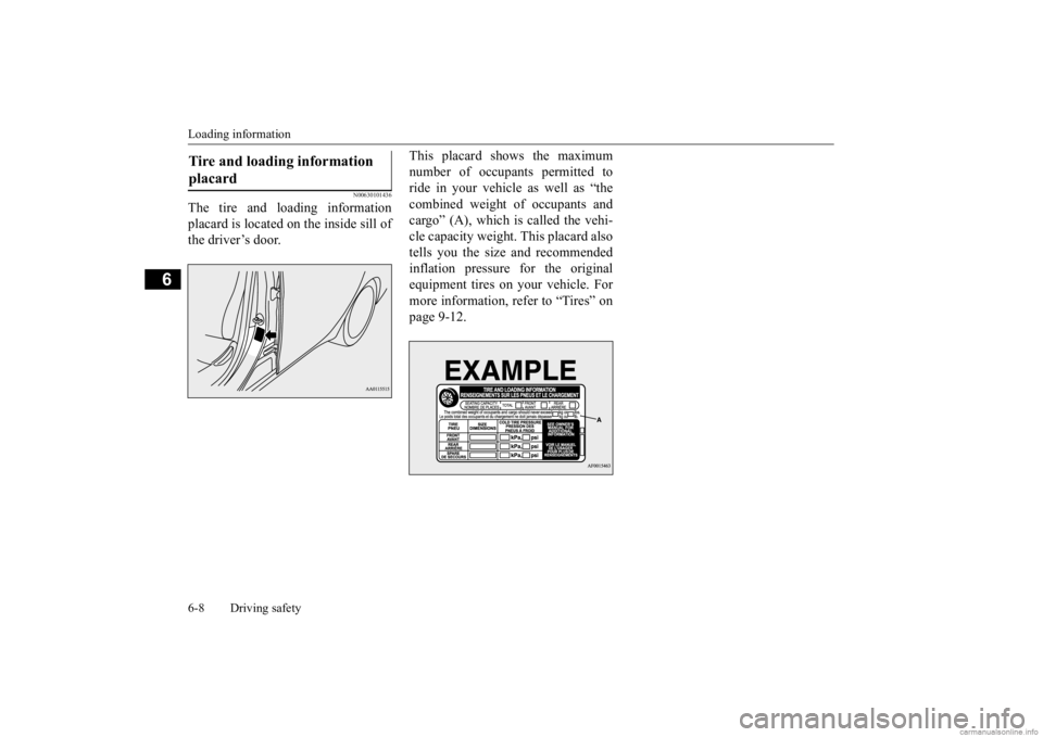
The tire and loading information placard is located on the inside sill of the driver’s door.
This placard shows the maximum number of occupants permitted to ride in your vehicle as well as “the combined weight of occupants andcargo” (A), which is called the vehi- cle capacity weight. This placard also tells you the size and recommendedinflation pressure for the original equipment tires on your vehicle. For more information, refer to “Tires” onpage 9-12.
Tire and loading information placard BK0284300US.book 8 ページ 2019年5月23日 木曜日 午後12時22分
Page 189 of 253
How to change a tire 8-8 For emergencies
8
N00849801529
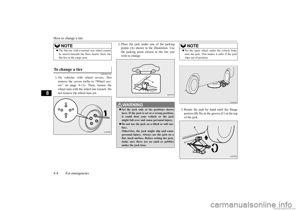
1. On vehicles with
wheel covers, first
remove the covers (refer to “Wheel cov- ers” on page 8-11). Then, loosen thewheel nuts with the wheel nut wrench. Do not remove the wheel nuts yet.
2. Place the jack under one of the jacking points (A) shown in th
e illustration. Use
the jacking point closest to the tire you wish to change.
3. Rotate the jack by hand until the flange portion (B) fits in the groove (C) at the top of the jack.
NOTE
The flat tire with a
normal size wheel cannot
be stored beneath the floor board. Store theflat tire in the cargo area.
To change a tire
WA R N I N G Set the jack only at
the positions shown
here. If the jack is set at a wrong position, it could dent your vehicle or the jackmight fall over and ca
use personal injury.
Do not use the jack on a tilted or soft sur- face. Otherwise, the jack might slip and cause personal injury. Always
use the jack on a
flat, hard surface. Before setting the jack, make sure there are no sand or pebbles under the jack base.
NOTE
Put the spare wheel
under the vehicle body
near the jack. This makes it safer if the jackslips out of position.
BK0284300US.book 8 ページ 2019年5月23日 木曜日 午後12時22分
Page 192 of 253
How to change a tire
For emergencies 8-11
8
N00850001198
Store the flat tire in the cargo area. Reverse the removing procedure when stor-ing the spare tire, jack, bar and wheel nut wrench. Refer to “To remove compact spare tire” onpage 8-7 and “Jack and tools” on page 8-5.
N00849401251
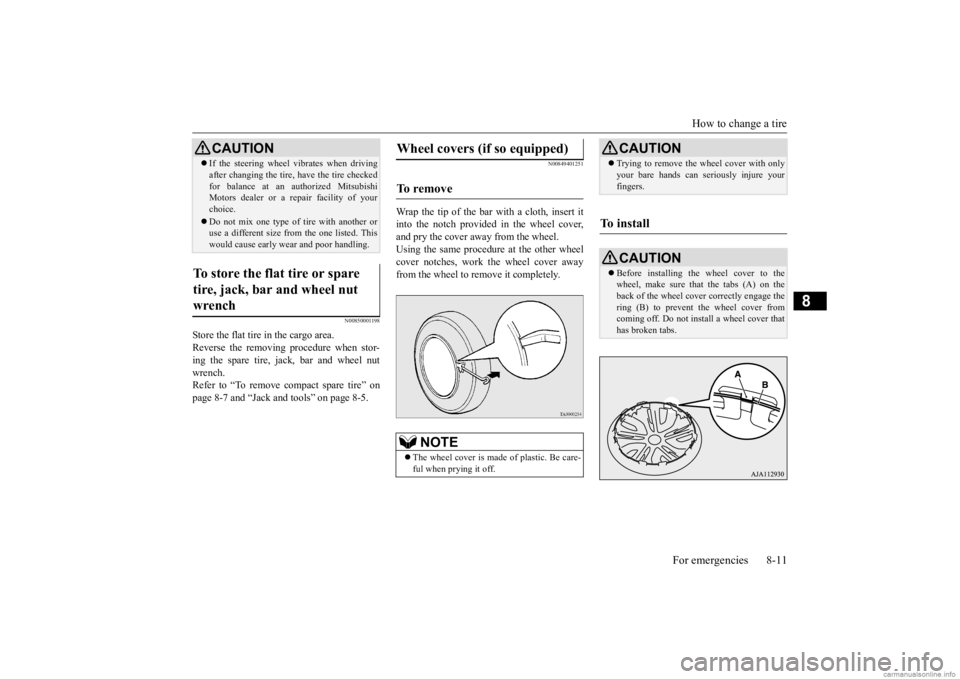
Wrap the tip of the bar with a cloth, insert itinto the notch provided in the wheel cover, and pry the cover away from the wheel. Using the same procedure at the other wheelcover notches, work the wheel cover away from the wheel to remove it completely.
If the steering wheel vibrates when driving after changing the tire, have the tire checkedfor balance at an authorized MitsubishiMotors dealer or a repair facility of your choice. Do not mix one type of tire with another or use a different size from the one listed. This would cause ea
rly wear and poor handling.
To store the flat tire or spare tire, jack, bar and wheel nut wrench
CAUTION
Wheel covers (if so equipped) To r e m o v e
NOTE
The wheel cover is made
of plastic. Be care-
ful when prying it off.
CAUTION Trying to remove the
wheel cover with only
your bare hands can seriously injure yourfingers.
To install
CAUTION Before installing the wheel cover to the wheel, make sure that the tabs (A) on the back of the wheel cove
r correctly engage the
ring (B) to prevent the wheel cover fromcoming off. Do not install a wheel cover that has broken tabs.
BK0284300US.book 11 ページ 2019年5月23日 木曜日 午後12時22分
Page 211 of 253
Tires 9-14 Vehicle care and maintenance
9
EXAMPLE: P215/65R15
EXAMPLE: 95H
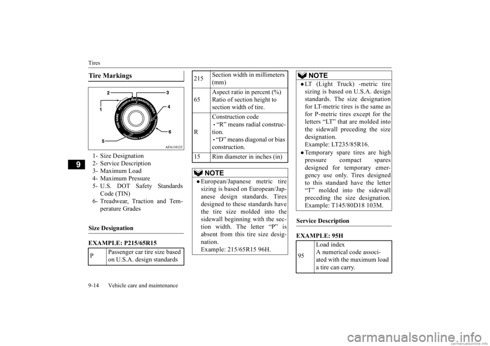
Tire Markings 1- Size Designation 2- Service Description3- Maximum Load 4- Maximum Pressure 5- U.S. DOT Safety Standards
Code (TIN)
6- Treadwear, Traction and Tem-
perature Grades
Size Designation P
Passenger car tire size based on U.S.A. design standards
215
Section width in millimeters (mm)
65
Aspect ratio in percent (%) Ratio of section height to section width of tire.
R
Construction code • “R” means radial construc- tion. • “D” means diagonal or bias construction.
15 Rim diameter in inches (in)
NOTE
European/Japanese metric tire sizing is based on European/Jap- anese design standards. Tiresdesigned to these standards have the tire size molded into the sidewall beginning with the sec-tion width. The letter “P” is absent from this tire size desig- nation.Example: 215/65R15 96H.
LT (Light Truck) -metric tiresizing is based on U.S.A. design standards. The size designation for LT-metric tires is the same asfor P-metric tires except for the letters “LT” that are molded into the sidewall preceding the sizedesignation. Example: LT235/85R16.Temporary spare tires are highpressure compact spares designed for temporary emer-gency use only. Tires designed to this standard have the letter “T” molded into the sidewallpreceding the si
ze designation.
Example: T145/80D18 103M.
Service Description 95
Load index A numerical code associ- ated with the maximum load a tire can carry.
NOTE
BK0284300US.book 14 ページ 2019年5月23日 木曜日 午後12時22分