engine MITSUBISHI MONTERO 1984 1.G Workshop Manual
[x] Cancel search | Manufacturer: MITSUBISHI, Model Year: 1984, Model line: MONTERO, Model: MITSUBISHI MONTERO 1984 1.GPages: 21, PDF Size: 1.29 MB
Page 1 of 21
. . c-, :
Service Manual
MONTERO
1984
FOREWORD
This Sk-vice Manual has been prepared with the latest
service information available at the time of publi-
cation. It is subdivided into various group categories
-and each section contains diagnosis, disassembly,
repair, and installation procedures along with com-
plete specifications and tightening references. Use of
this manual will aid in properly performing any
servicing necessary to maintain or restore the high
levels of performance and reliability designed into
these outstanding vehicles.
WE SUPPORT l VOLUNTARY TECHNICIAN
CERTIFICATION
THROUGH
.&tsubishi Motors Corporation reserves the right to make changes in
Zesign or to make additions to or improvements in its products without
mposing any obligations upon itself to install them on its products
.reviously manufactured. Introduction . , . .,......,..........
0 Lubrication and Maintenance . . . . . . . . .
2
3
5
6 Front Suspension ..................
RearAxle:. ......................
Brakes - Service and Parking .........
Clutch ..........................
7
8 Cooling ...........................
Electrical System ..................
9
11 Engine ...........................
Exhaust System .....................
13 Body and Frame Alignment . . . . . . . . . .
14 Fuel System . , . . . . . . . . . . .,. . . . . . . . .
16 Propeller Shaft and Universal Joints . . .,.
17 Rear Suspension . . . . . . . . . . . . . . . . . . .
19 Steering - Power . . . . . . . . . . . . . . ., . . .
21 Manual
Transmission - Automatic .,........
22 Wheels and Tires. . . , . . . , , . . . . . . . . . .
23 Body and Sheet Metal , . . . . . . . . . . . . .
24 Heaters and Air-conditioning . . . . . . . . .
25 Emission Control Systems . . . . . . . . . . .
GROUP INDEX Alphabetical Index
0 1983 Mitsubishi Motors Corporation Printed in Japan
Page 3 of 21
VEHICLE IDENTIf~CATlON
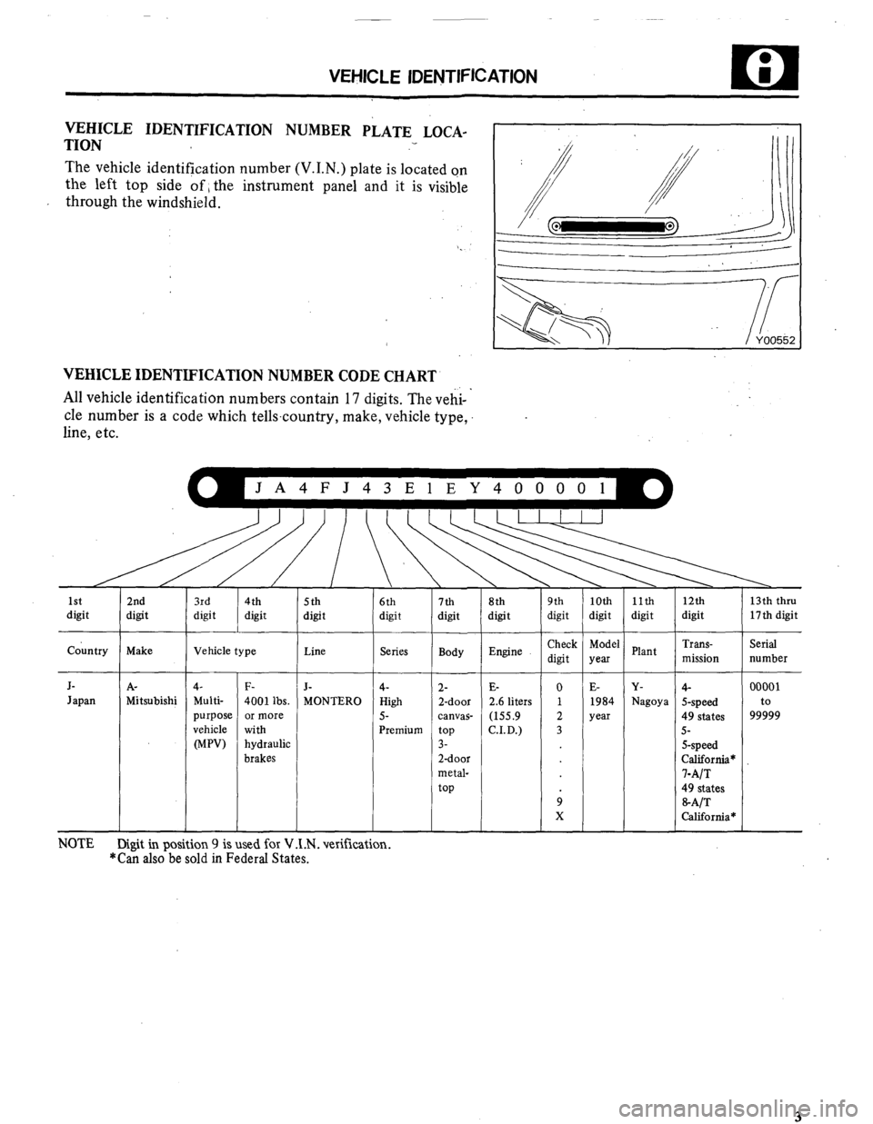
VEHICLE IDENTIFICATION NUMBER PLATE LOCA-
TION
The vehicle identification number (V.I.N.) plate is located on
the left top side of 1 the instrument panel and it is visible
through the windshield.
VEHICLE IDENTIFICATION NUMBER CODE CHART
All vehicle identification numbers contain 17 digits. The vehi- ’
cle number is a code which tellscountry, make, vehicle type,
line, etc.
JA4FJ43ElEY400001
I
5th
digit
I
1st
digit 2nd
digit
country Make
J- A-
Japan Mitsubishi 6th
digit 7th 8th
digit digit
Series
Body
4-
High
5-
Premium 2-
2-door
canvas-
top
3-
2-door
metal-
top 11th
digit 9th
digit
Check
digit Vehicle type : 10th
digit
Model
yea
E-
1984
year 12th
digit
Trans-
mission
4-
S-speed
49 states
5-
S-speed
California*
l-A/T
49 states
&A/T
California* 13th thru
17th digit
Serial
number
00001
to
99999 Plant
Y-
Nagoya Line Engine ,
J-
MONTERO E-
2.6 liters
(155.9
CID.) 4-
Multi-
purpose
vehicle
WV) F-
4001 lbs.
or more
with
hydraulic
brakes NOTE
Digit in position 9 is used for V .1 .N . verification. *Can also be sold in Federal States.
Page 4 of 21
I
I
cl ; VElfICLE IDENTIFICATION
/
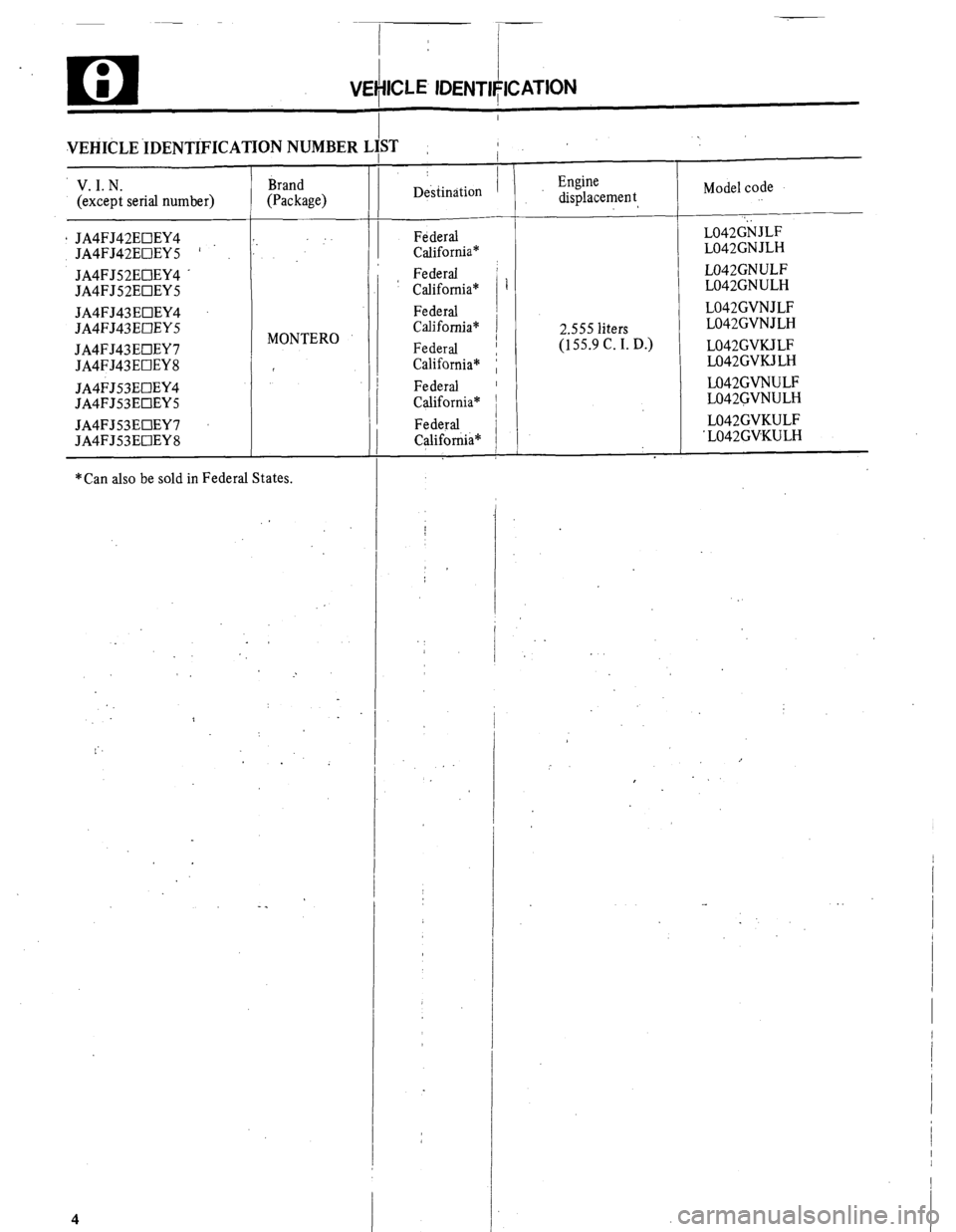
VEHICLE .IDENTiFICATION NUMBER L;ST
V. I. N.
(except serial number)
* JA4FJ42EOEY4
JA4FJ42EOEYS ’
JA4FJ52EUEY4 .
JA4FJ52EOEYS
JA4FJ43EOEY4
JA4FJ43EUEYS
JA4FJ43EUEY7
JA4FJ43EOEY8
JA4FJ53EClEY4
JA4FJ53EOEYS
JA4FJ53EOEY7
JA4FJ53EClEY8 Brand
(Package)
MONTERO
*Can also be sold in Federal States. Destination I
FdderaJ
California*
Federal
California*
Federal
California*
Federal
California*
Federal
California*
Federal
Califorrh” i
T
-
T
Engine
displacement
2.555 liters
(155.9 C. I. D.) Model code
‘. LO42GN JLF
L042GNJLH
L042GNULF
L042GNULH
L042GVNJLF
L042GVNJLH
L042GVKJLF
L042GVKJLH
LO42GVNULF
L042GVNULH
L042GVKULF
‘L042GVKULH
Page 5 of 21
VEHICLE IDENTIFICATION
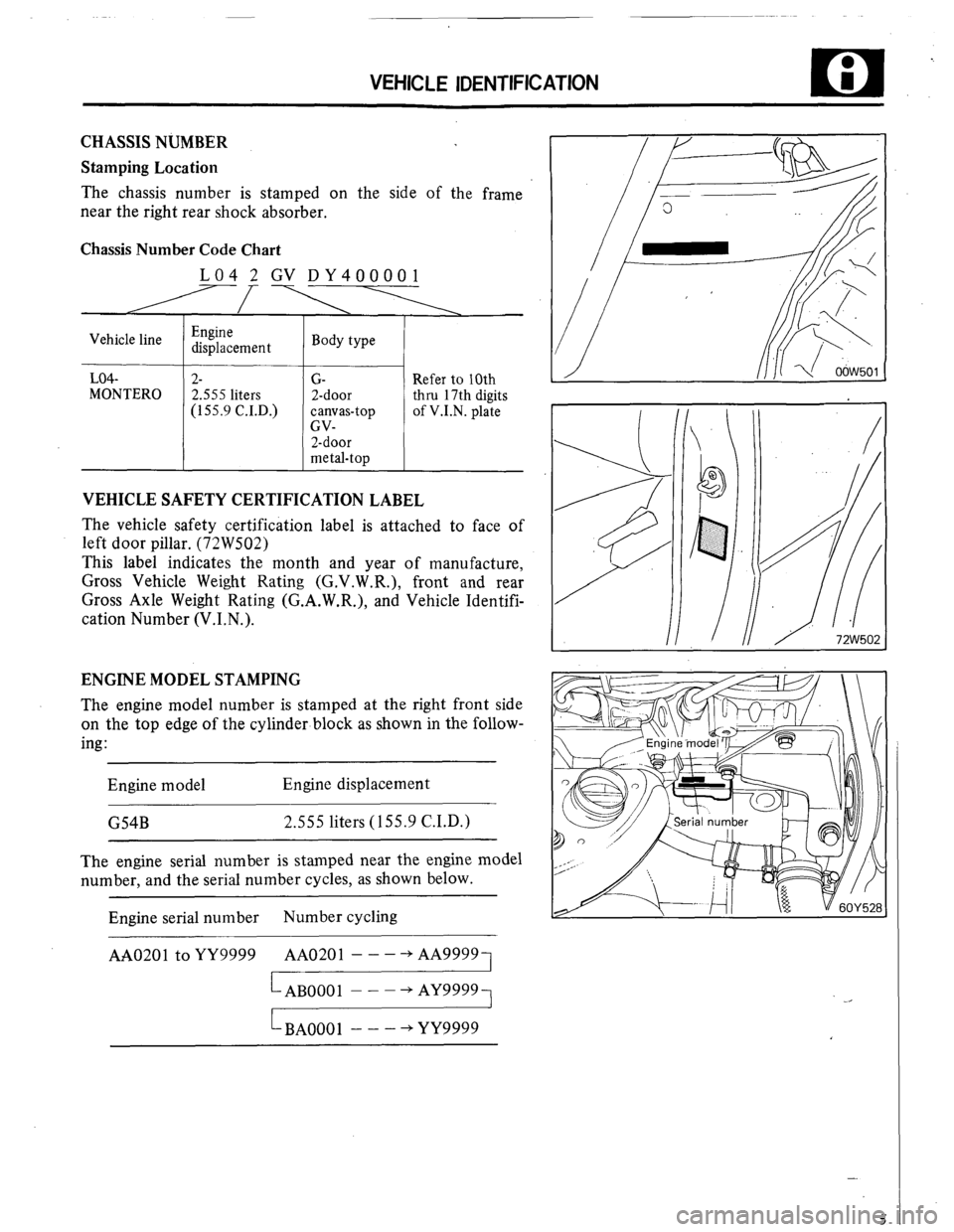
CHASSIS NUMBER
Stamping Location
The chassis number is stamped on the side of the frame
near the right rear shock absorber.
Chassis Number Code Chart
LO4 2 GV DY400001
Vehicle line
LO4-
7
MONTERO
I
Engine
displacement
2-
2.555 liters
(155.9 C.I.D.) Body type
G-
2-door
canvas-top
GV-
2-door
metal-top
1
Refer to 10th
thru 17th digits
of V.I.N. plate
VEHICLE SAFETY CERTIFICATION LABEL
The vehicle safety certification label is attached to face of
left door pillar. (72W502)
This label indicates the month and year of manufacture,
Gross Vehicle Weight Rating (G.V.W.R.), front and rear
Gross Axle Weight Rating (G.A.W.R.), and Vehicle Identifi-
cation Number (V.I.N.).
ENGINE MODEL STAMPING
The engine model number is stamped at the right front side
on the top edge of the cylinder block as shown in the follow-
ing :
Engine model Engine displacement
G54B 2.555 liters (155.9 C.I.D.)
The engine serial number is stamped near the engine model
number, and the serial number cycles, as shown below.
Engine serial number Number cycling i
AA0201 to YY9999 AA0201 - - - -+ AA99991
LAB0001 - - - + AY9999
LBAOOOl - - - += YY9999
5
Page 6 of 21
i 1
I
VEHICLE IDENTIFICATION
I
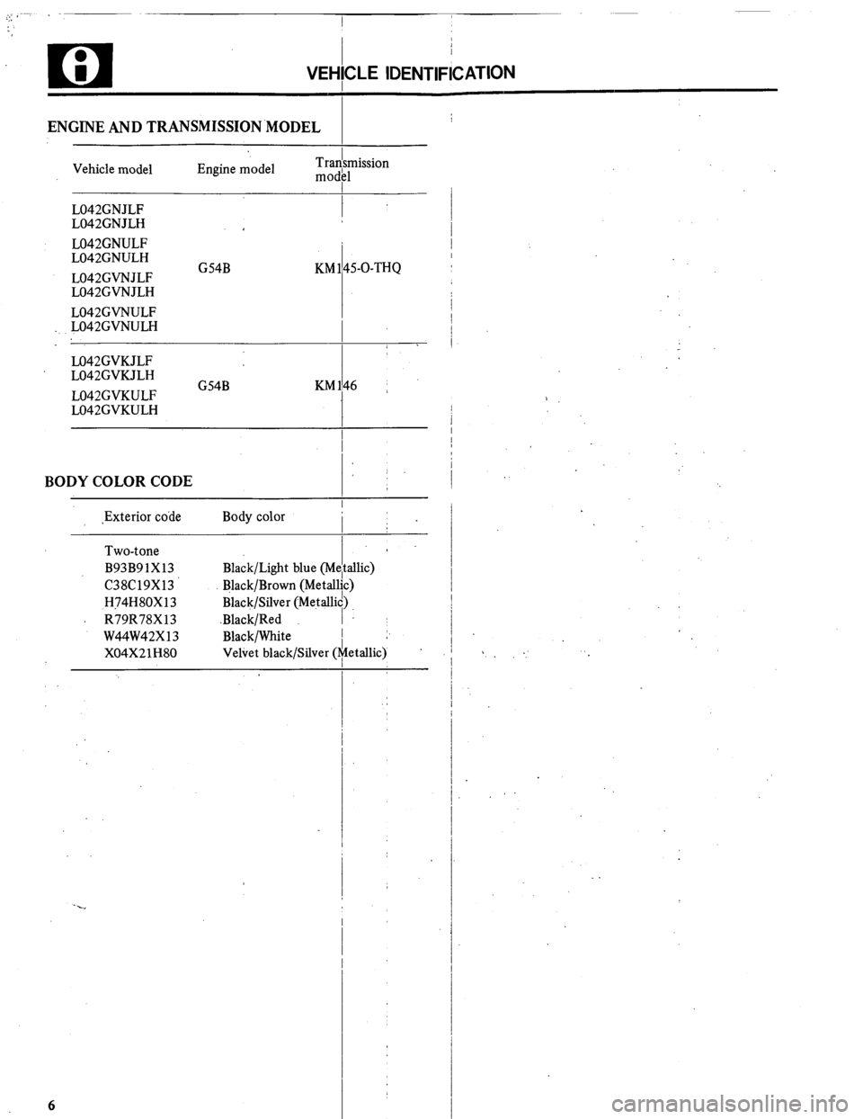
ENGINE AND TRANSMISSION.MODEL
Vehicle model Engine model Tradsmission
mod11
L042GNJLF
I
L042GNJLH
L042GNULF
L042GNULH
L042GVNJLF G54B KM 145-O-THQ
L042GVNJLH
L042GVNULF
L042GVNULH
1 .
M42GVKJLF
L042GVKJLH
L042GVKULF G54B KM146 ~
L042GVKULH
I
BODY COLOR CODE
,Exterior code Body color
Two-tone
B93B91X13
C38C19X13
H74H80X13
A R79R78X13
W44W42X13
X04X21H80 Black/Light blue (M
Black/Brown (Metal
Black/Silver (Metalk
.Black/Red
Black/White
Veliet black/Silver (
6
i
efi
lit
id)
I
:“:
T sllic)
>
etallic) :
Page 9 of 21
PRECAUTIONS BEFORE SERVICE
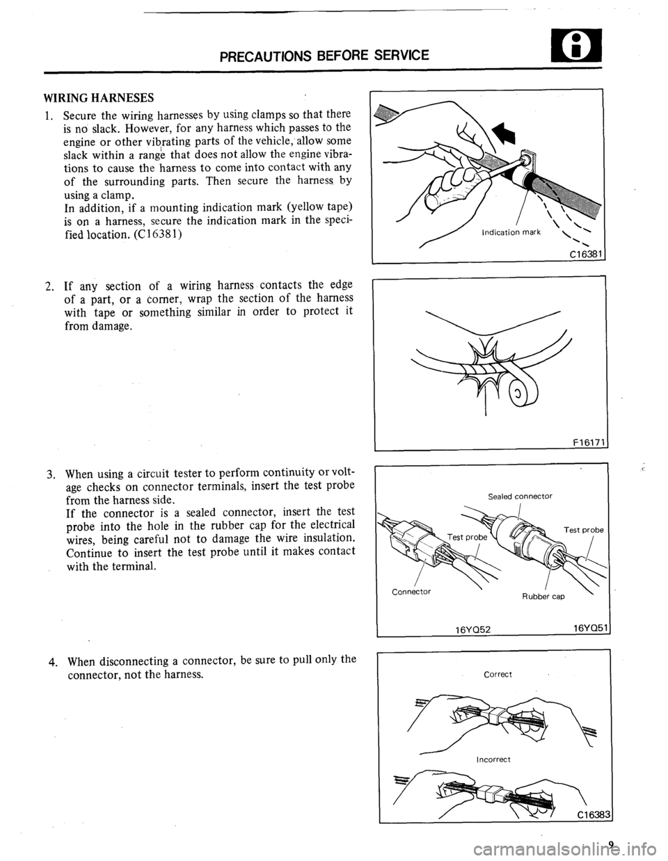
WIRING HARNESES
1. Secure the wiring harnesses by using clamps so that there
is no slack. However, for any harness which passes to the
engine or other vibrating parts of the vehicle;allow some
slack within a range that does not allow the engine vibra-
tions to cause the harness to come into contact with any
of the surrounding parts. Then secure the harness. by
using a clamp.
In addition, if a mounting indication mark (yellow tape)
is on a harness, secure the indication mark in the speci-
fied location. (C 1638 1)
2. If any section of a wiring harness contacts the edge
of a part, or a corner, wrap the section of the harness
with tape or something similar in order to protect it
from damage.
3. When using a circuit tester to perform continuity or volt-
age checks on connector terminals, insert the test probe
from the harness side.
If the connector is a sealed connector, insert the test
probe into the hole in the rubber cap for the electrical
wires, being careful not to damage the wire insulation.
Continue to insert the test probe until it makes contact
with the terminal.
4. When disconnecting a connector, be sure to pull only the
connector, not the harness.
F1617
Sealed connector
I 16YQ52 16YQ5
Correct
I Incorrect 1
Page 11 of 21
. . .
PRECAUTIONS BEFORE SERVICE
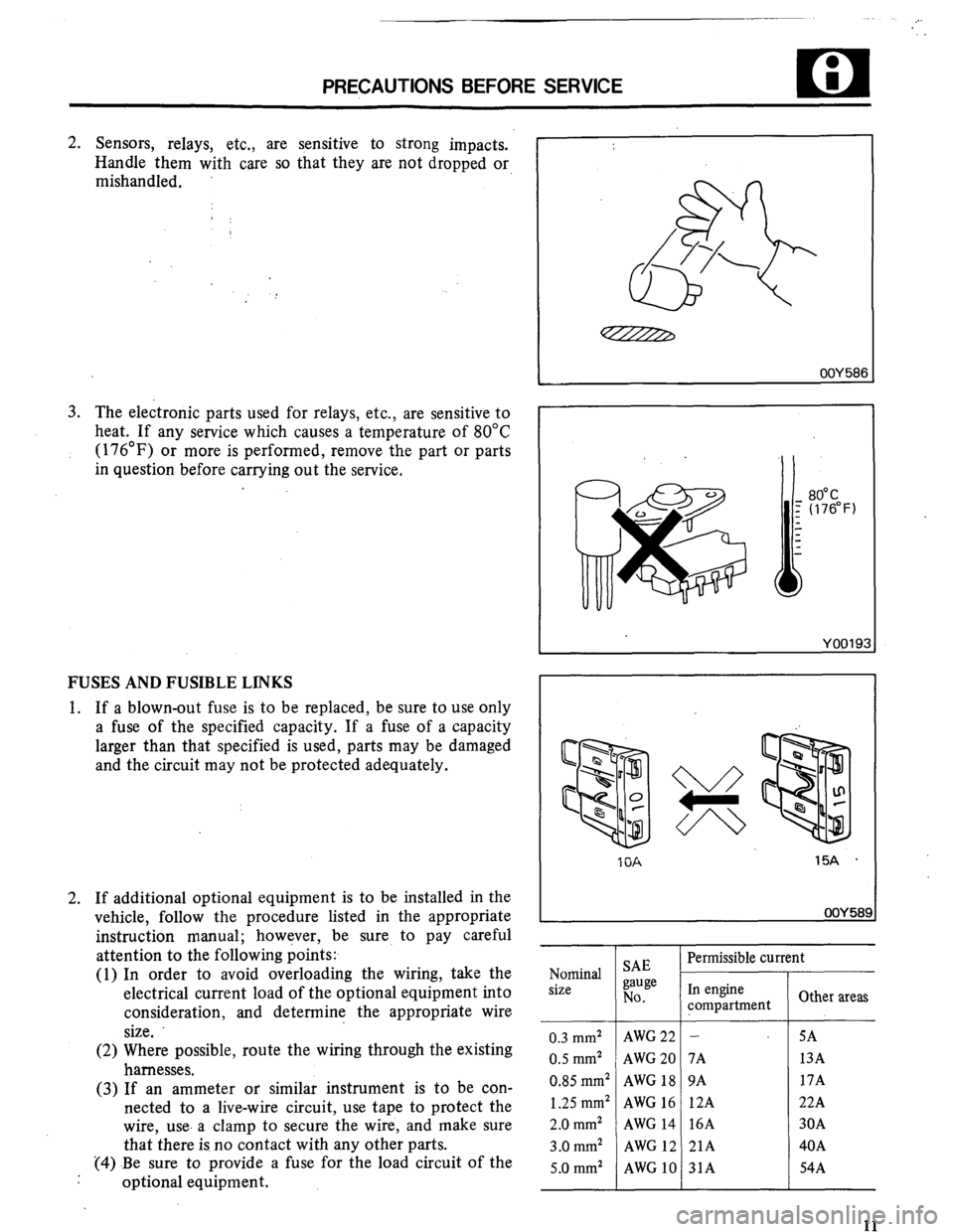
2. Sensors, relays, etc., are sensitive to strong impacts.
Handle them with care so that they are not dropped or,
mishandled.
3. The electronic parts used for relays, etc., are sensitive to
heat. If any service which causes a temperature of 80°C
(176’F) or more is performed, remove the part or parts
in question before carrying out the service,
FUSES AND FUSIBLE LINKS
1. If a blown-out fuse is to be replaced, be sure to use only
a fuse of the specified capacity. If a fuse of a capacity
larger than that specified is used, parts may be damaged
and the circuit may not be protected adequately.
2. If additional optional equipment is to be installed in the
vehicle, follow the procedure listed in the appropriate
instruction manual; however, be sure to pay careful
attention to the following points:
(1) In order to avoid overloading the wiring, take the
electrical current load of the optional equipment into
consideration, and determine the appropriate wire
size.
(2) Where possible, route the wiring through the existing
harnesses.
(3) If an ammeter or similar instrument is to be con-
nected to a live-wire circuit, use tape to protect the
wire, use. a clamp to secure the wire, and make sure
that there is no contact with any other parts.
(4) Be sure to provide a fuse for the load circuit of the
optional equipment.
OOY 58E
15A .
OOY 582
Nominal
size
0.3 mm2
0.5 mm2
0.85 mm2
1.25 mm2 2.0
mm2 3.0
mm2
5.0 mm2 SAE
gauge
No.
AWG 22
AWG 20
AWG 18
AWG 16
AWG 14
AWG 12
AWG 10
Permissible current
In engine
compartment
-
7A
9A
12A
16A
21A
31A Other areas
SA
13A
17A
22A
30A
40A
54A 11
Page 17 of 21
GENERAL DATA AND SPECIFICATIONS
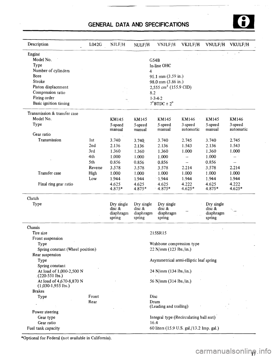
Description
LO42G NJLF/H
NULFIH VNJLF/H ViULF/H VNULF/H VKULF/H
Engine
Model No.
Type
Number of cylinders
Bore
Stroke
Piston displacement
Compression ratio
Firing order
Basic ignition timing
Transmission & transfer case
Model No.
Type
Gear ratio
Transmission
Transfer case
Final ring gear ratio G54B
In-line OHC
4
9i.l mm (3.59 in.)
98.0 mm (3.86 in.)
2,555 cm3 (155.9 CID)
8.2
-3 l-3-4-2
7”BTDC + 2”
KM145 KM145
S-speed 5-speed
manual manual KM145
5-speed
manual KM146 KM145 KM146
3-speed 5-speed 3-speed
automatic manual automatic
1st 3.740 3.740, 3.740 2.745 3.740 2.745
2nd 2.136 2.136 2.136 1.543 2.136 1.543
3rd 1.360 1.360 1.360 1 .ooo 1.360 1 .OOO
4th 1 .ooo 1 .ooo 1.000 - 1 .ooo
5th 0.856 0.856 0.856 - 0.856 -
Reverse 3.578 3.578 3.578 2.214 3.578 2.214
High
Low 1 .ooo 1 .ooo 1 .ooo 1 .ooo 1 .ooo 1 .ooo
1.944 1.944 1.944 1.944 1.944 1.944
4.625 4.625 4.625 4.222 4.625 4.222
4.875* 4.875” 4.875* 4.625* 4.875” 4.625*
Clutch
Type
Chassis
Tire size
Front suspension
Type
Spring constant (Wheel position)
Rear suspension
Type
Spring constant
At load of 1 ,OOO-2,500 N
(220-551 lbs.)
At load of 4,670-8,870 N
(1,030-1,955 lbs.)
Brakes
Type Front
Rear
Power steering
Gear type
Gear ratio
Fuel tank capacity Dry single Dry single Dry single
disc & disc & disc &
diaphragm diaphragm diaphragm -
spring spring spring Dry single
disc & ‘,
diaphragm -
spring
215SR15
Wishbone compression type
22 N/mm (123 lbs./in.)
Asymmetrical semi-elliptic leaf spring
24 N/mm (134 lbs ./in.)
56 N/mm (3 14 Ibs./in.)
Disc
Drum
(Leading and trailing)
Integral type (Recirculating ball nut).
16.4
60 liters (15.9 U.S. ga.lJ13.2 Imp. gal.)
*Optional for Federal (not available in California).
17