light MITSUBISHI MONTERO 1984 1.G Workshop Manual
[x] Cancel search | Manufacturer: MITSUBISHI, Model Year: 1984, Model line: MONTERO, Model: MITSUBISHI MONTERO 1984 1.GPages: 21, PDF Size: 1.29 MB
Page 6 of 21

i 1
I
VEHICLE IDENTIFICATION
I
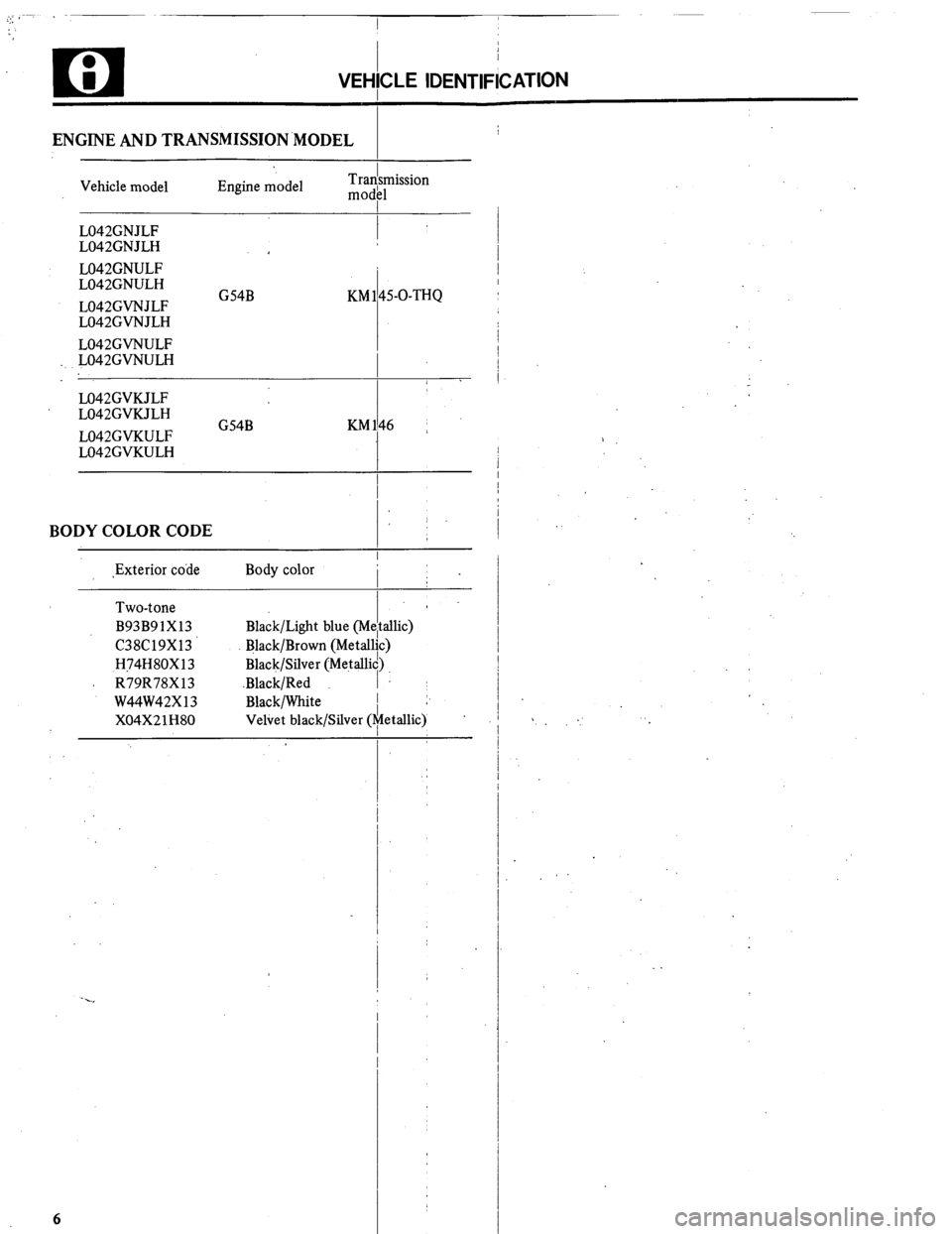
ENGINE AND TRANSMISSION.MODEL
Vehicle model Engine model Tradsmission
mod11
L042GNJLF
I
L042GNJLH
L042GNULF
L042GNULH
L042GVNJLF G54B KM 145-O-THQ
L042GVNJLH
L042GVNULF
L042GVNULH
1 .
M42GVKJLF
L042GVKJLH
L042GVKULF G54B KM146 ~
L042GVKULH
I
BODY COLOR CODE
,Exterior code Body color
Two-tone
B93B91X13
C38C19X13
H74H80X13
A R79R78X13
W44W42X13
X04X21H80 Black/Light blue (M
Black/Brown (Metal
Black/Silver (Metalk
.Black/Red
Black/White
Veliet black/Silver (
6
i
efi
lit
id)
I
:“:
T sllic)
>
etallic) :
Page 8 of 21

u ; I
PRECAl/TlONS BEFOFE SERVICE
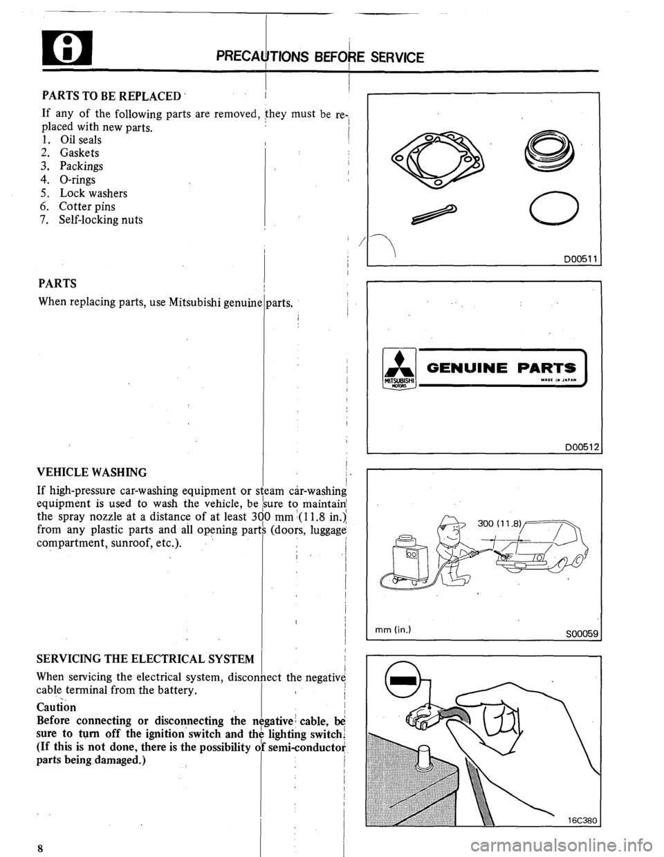
PARTS TO BE REPLACED I I
If any of the following parts are removed, they must be re-i
placed with new parts.
1. Oil seals
2. Gaskets
3. Packings
4. O-rings
5. Lock washers
6. Cotter pins
7. Self-locking nuts
0
2
Q’
0
0
0
PARTS
.i genuin When replacing parts, use Mitsubish
VEHICLE WASHING
If high-pressure car-washing equipment or I
equipment is used to wash the vehicle, be
the spray nozzle at a distance of at least 3
from any plastic parts and all opfning par
compartment, sunroof, etc.).
SERVICING THE ELECTRICAL SYSTEM
When servicing the electrical system, discor
cab!e terminal from the battery.
Cautibn
Before connecting or disconnecting the I
sure to turn off the ignition’ switch and tl
(If this is not done, there is the possibility 1
parts being-damaged.) :
8
;te
: Is1
00
th jarts.
I
am &r-washing
Ire to maintain1
mm 1(11.8 in.>’
(doors, luggagk
ect the negativ
e:
:ativei cable, b
lighting switch
semi-conducta /
-3
D0051:
mm (in.)
SOOO5~
Page 13 of 21

TOWING AND HOISTING
TOWING AND HOISTING
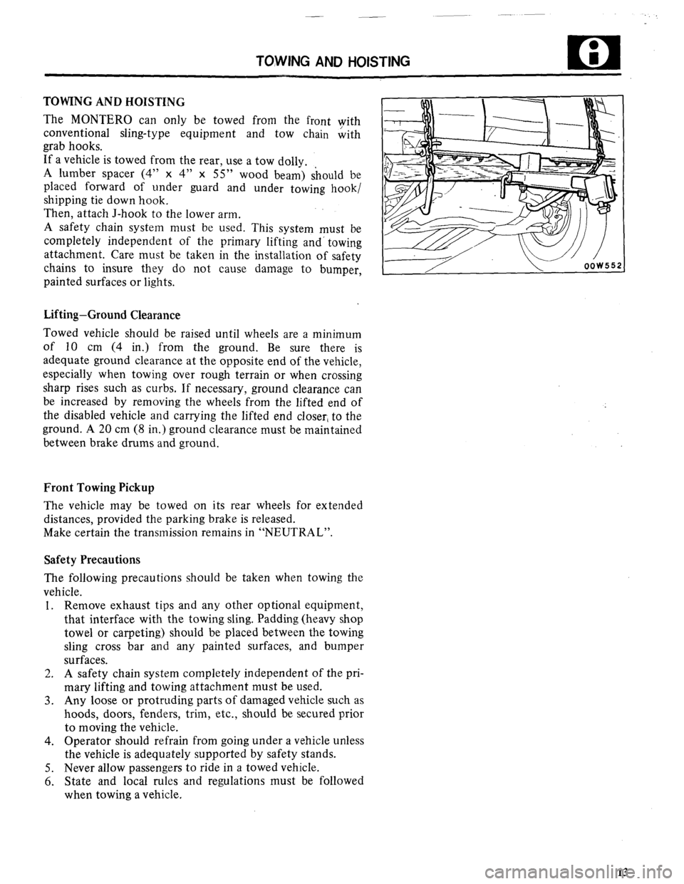
The MONTERO can only be towed from the front with
conventional sling-type equipment and tow chain &th
grab hooks.
If a vehicle is towed from the rear, use a tow dolly.
A lumber spacer (4” x 4” x 55” wood beam) should be
placed forward of under guard and under towing hook/
shipping tie down hook.
Then, attach J-hook to the lower arm.
A safety chain system must be used. This system must be
completely independent of the primary lifting and’ towing
attachment. Care must be taken in the installation of safety
chains to insure they do not cause damage to bumper,
painted surfaces or lights.
Lifting-Ground Clearance
Towed vehicle should be raised until wheels are a minimum
of 10 cm (4 in.) from the ground. Be sure there is
adequate ground clearance at the opposite end of the vehicle,
especially when towing over rough terrain or when crossing
sharp rises such as curbs. If necessary, ground clearance can
be increased by removing the wheels from the lifted end of
the disabled vehicle and carrying the lifted end closer, to the
ground. A 20 cm (8 in.) ground clearance must be maintained
between brake drums and ground.
Front Towing Pickup
The vehicle may be towed on its rear wheels for extended
distances, provided the parking brake is released.
Make certain the transmission remains in “NEUTRAL”.
Safety Precautions
The following precautions should be taken when towing the
vehicle.
1. Remove exhaust tips and any other optional equipment,
that interface with the towing sling. Padding (heavy shop
towel or carpeting) should be placed between the towing
sling cross bar and any painted surfaces, and bumper
surfaces.
2. A safety chain system completely independent of the pri-
mary lifting and towing attachment must be used.
3. Any loose or protruding parts of damaged vehicle such as
hoods, doors, fenders, trim, etc., should be secured prior
to moving the vehicle.
4. Operator should refrain from going under a vehicle unless
the vehicle is adequately supported by safety stands.
5. Never allow passengers to ride in a towed vehicle.
6. State and local rules and regulations must be followed
when towing a vehicle.
13