flasher MITSUBISHI MONTERO 1987 1.G User Guide
[x] Cancel search | Manufacturer: MITSUBISHI, Model Year: 1987, Model line: MONTERO, Model: MITSUBISHI MONTERO 1987 1.GPages: 284, PDF Size: 14.74 MB
Page 96 of 284
![MITSUBISHI MONTERO 1987 1.G User Guide 8-76 CHARGING SYSTEM - Circuit Diagram
3 CHARGING CIRCUIT
Battery Ignition switch
OFF
Main
m fusible ’ L
link
A-02
fl.3-Br 1~5~~
, A-23 Sub fusible link
(IGN . SW)
IAM IG ] c-55
3
3
A MITSUBISHI MONTERO 1987 1.G User Guide 8-76 CHARGING SYSTEM - Circuit Diagram
3 CHARGING CIRCUIT
Battery Ignition switch
OFF
Main
m fusible ’ L
link
A-02
fl.3-Br 1~5~~
, A-23 Sub fusible link
(IGN . SW)
IAM IG ] c-55
3
3
A](/img/19/7559/w960_7559-95.png)
8-76 CHARGING SYSTEM - Circuit Diagram
3 CHARGING CIRCUIT
Battery Ignition switch
OFF
Main
m fusible ’ L
link
A-02
fl.3-Br 1~5~~
, A-23 Sub fusible link
(IGN . SW)
IAM IG ] c-55
3
3
A m
A
To turn signal flasher
unit [Refer to P.8-49.1 Multi-
n, Irnn4P
ComSeter
Remark
For information concerning the ground points (example:
q ),
refer to P.8-7. 37W605
Wiring color code
B: Black Br: Brown G: Green Gr: Gray L: Blue Lg: Light green
LI: Light blue 0: Orange P: Pink R: Red Y: Yellow W: White
1 STB Revision
Page 163 of 284
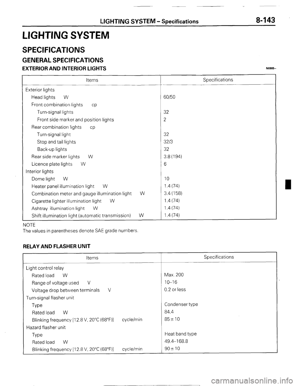
LIGHTING SYSTEM - Specifications 8-143
LIGHTING SYSTEM
SPECIFICATIONS
GENERAL SPECIFICATIONS
EXTERIOR AND INTERIOR LIGHTS NOEIB-
Items
Exterior lights
Head lights W
Front combination lights cp
Turn-signal lights
Front side marker and position lights
Rear combination lights cp
Turn-signal light
Stop and tail lights
Back-up lights
Rear side marker lights W
Licence plate lights W
Interior lights
Dome light W
Heater panel illumination light W
Combination meter and gauge illumination light
Cigarette lighter illumination light
W
Ashtray illumination light
W
Shift illumination light (automatic transmission) W
W
NOTE
The values in parentheses denote SAE grade numbers.
RELAY AND FLASHER UNIT
Items
Light control relay
Rated load W
Range of voltage used V
Voltage drop between terminals V
Turn-signal flasher unit
Type
Rated load W
Blinking frequency [I 2.8 V, 20°C (68”F)l
Hazard flasher unit
Type cycle/min
Rated load W
Blinking frequency [ 12.8 V, 20°C (68”F)l cycle/min Specifications
60/50
32
2
32
32/3
32
3.8(194)
6
10 1.4 (74)
3.4 (158)
1.4 (74)
1.4 (74)
1.4 (74)
Specifications
Max. 200
IO-16
0.2 or less
Condenser type
84.4
85210
Heat band type
49.4-168.8
902 10
1 STB Revision
Page 170 of 284
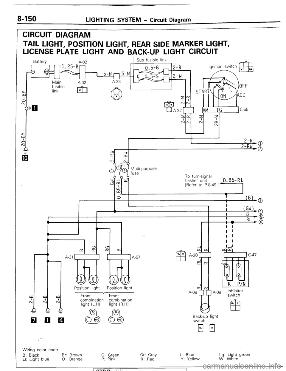
8-150 LIGHTING SYSTEM - Circuit Diagram
CIRCUIT DIAGRAM
TAIL LIGHT, POSITION LIGHT, REAR Sl!DE MARKER LIGHT,
LICENSE PLATE LIGHT AND BACK-UP LIGHT CIRCUIT
Battery
A-02 Sub fusible link
-1.25-B-
3
1 5-w r-l 5-w 1
Main
A-02 A-23
1m fusible
link
m w
3
cl
-22
To turn-signal
flasher unit 0.85-RL [Refer to P.8-49.]-
T
I lB’-@
Position light
Front A-57
Position light
v A-08 A-09 Inhibitor
Front switch - .
combination
light (L.H) _ _ combination
Ii-h+ IQ LA
Backy light
switch
i
Wiring color code
6: Black Br: Brown G: Green Gr: Gray L: Blue Lg: Light green
LI: Light blue 0: Orange P: Pink
R: Red Y: Yellow W: White
-
/ STB Revision --7
Page 173 of 284
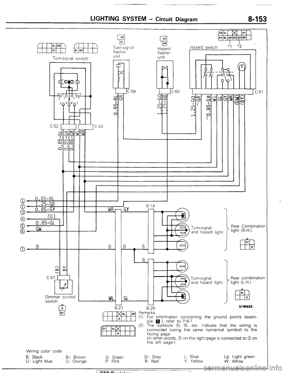
LIGHTING SYSTEM - Circuit Diagram 8-153
Turn-signal
flasher Hazard
flasher I iazard switch “1
unit unit
I r Turn-srgnal switch
I
l!d C-62
a
I
::
C
-W‘\*1W++ n
c
I
::
C
n
*
‘\&VB/
I v-l--c 0.85-RL
o- 1 ')r r-
Rear Combination
light (R.H.) Turn -signal
and hazard light B
Y-
a- B B
Dimmer control
switch Rear combination
light (L.H.) OL
EZB B
WL
37W029 B-20
-
m Rern~:~s~ ) refer to P 8-7. (1) For information concerning the ground points (exam-
(2) The symbols 0. 0, etc. indicate that the wiring is
connected (using the same numerical symbol) to the
(In other words, 0 on the right page is connected to 0 on
the left page.)
Wiring color code
B: Black Br: Brown
G: Green Gr: Gray L: Blue Lg: Light green
LI: Light blue
0: Orange P: Pink
R: Red Y: Yellow
W: White ) STB Revision
Page 209 of 284
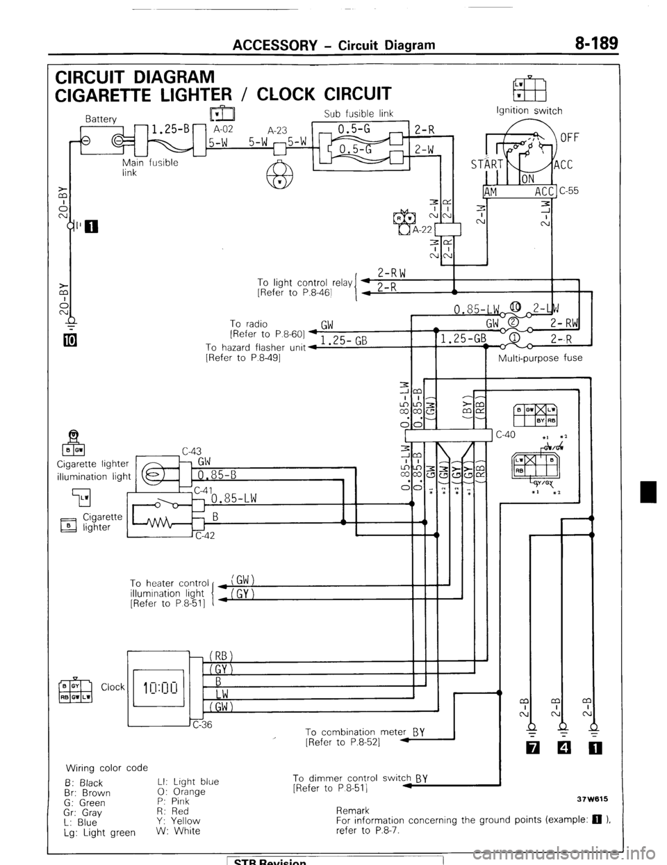
ACCESSORY - Circuit Diagram 8-189
CIRCUIT DIAGRAM
LW
CIGARETTE LIGHTER / CLOCK CIRCUIT EB w
Sub fusible link
,-fs q M 15-W 5-W 25-W m ;I;
I I
-
Main fusible -
link Ignition switch
3e
I I
NN
,
Z-RW To
linht cnntrnl r&v I 4 0 n
I 1 - .J . __._ - -., [Refer to P.8-461
I 4 L-K A
To radio
GW [Refer to P.8-601 + 1 .25- GB
To hazard flasher unit4
[Refer to P.8-491
Multi-purpose fuse
illumination light
’ To heater control
illumination light
[Refer to P 8-511
r
i I
To combination meter BY
Wiring color code
B: Black LI: Light blue
Br: Brown 0: Orange
G: Green P: Pink
Gr: Gray R: Red
L: Blue Y: Yellow
Lg: Light green W: White
I
I - - m
I
N
Q
-
[Refer to P.8-521 -
To dimmer control switch BY
[Refer to P 8-511 .I
Remark 37W615
For information concerning the ground points (example: 0 ).
refer to P.8-7.
1 STB Revision
Page 213 of 284
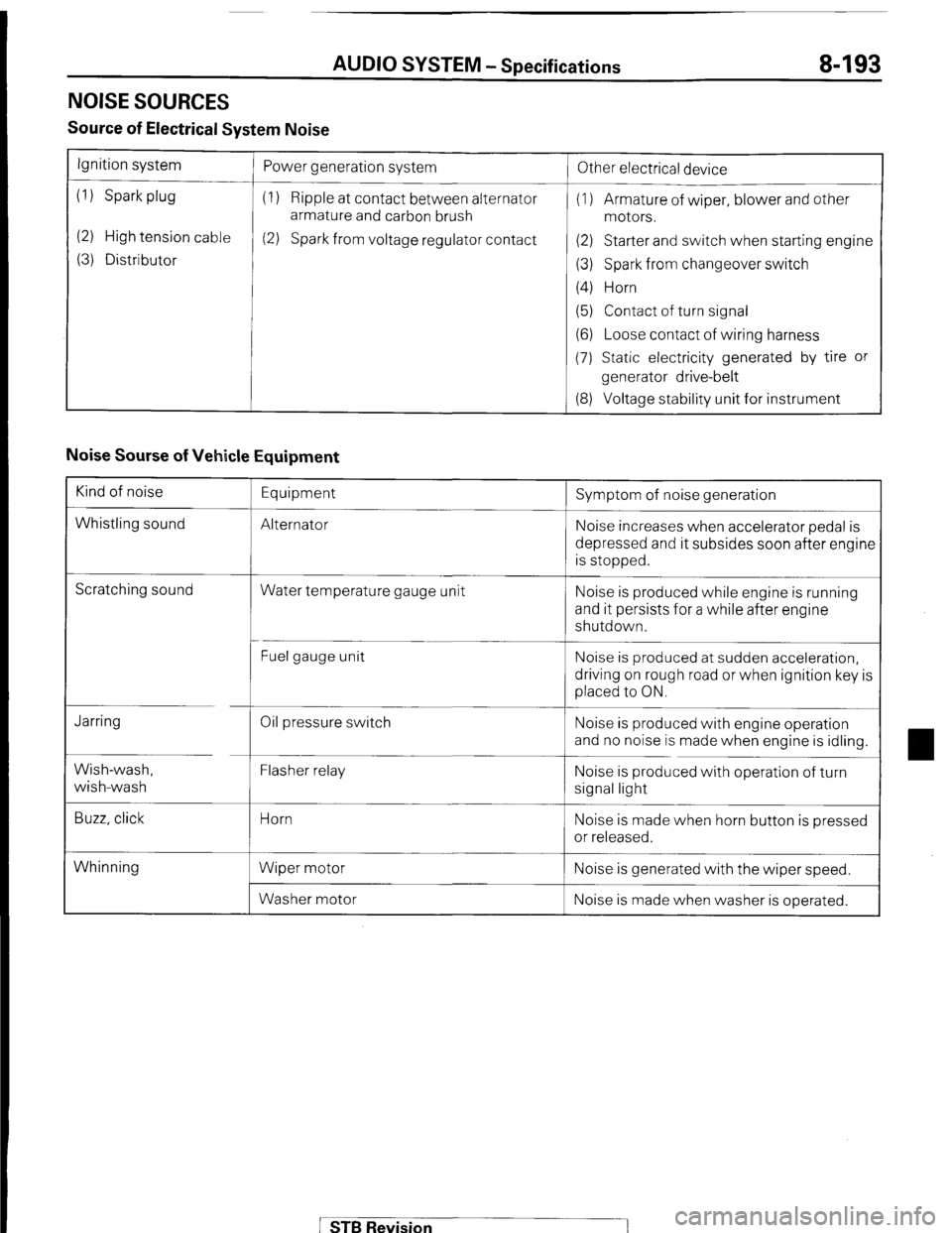
AUDIO SYSTEM - Specifications 8-193
NOISE SOURCES
Source of Electrical System Noise
Ignition system
(1) Spark plug
(2) High tension cable
(3) Distributor Power generation system
(1) Ripple at contact between alternator
armature and carbon brush
(2) Spark from voltage regulator contact
!
Other electrical device
(1) Armature of wiper, blower and other
motors.
(2) Starter and switch when starting engine
(3) Spark from changeover switch
(4) Horn
(5) Contact of turn signal
(6) Loose contact of wiring harness
(7) Static electricity generated by tire or
generator drive-belt
(8) Voltage stability unit for instrument
Noise Sourse of Vehicle Equipment
Kind of noise
Whistling sound Equipment
Alternator Symptom of noise generation
Noise increases when accelerator pedal is
depressed and it subsides soon after engine
is stopped.
Scratching sound
Water temperature gauge unit Noise is produced while engine is running
and it persists for a while after engine
shutdown.
Fuel gauge unit Noise is produced at sudden acceleration,
driving on rough road or when ignition key is
placed to ON.
Jarring
Wish-wash,
wish-wash
Buzz, click Oil pressure switch
Flasher relay
Horn
Wiper motor
Washer motor Noise is produced with engine operation
and no noise is made when engine is idling.
Noise is produced with operation of turn
signal light
Noise is made when horn button is pressed
or released.
Whinning Noise is generated with the wiper speed.
Noise is made when washer is operated.
STB Revision
Page 221 of 284
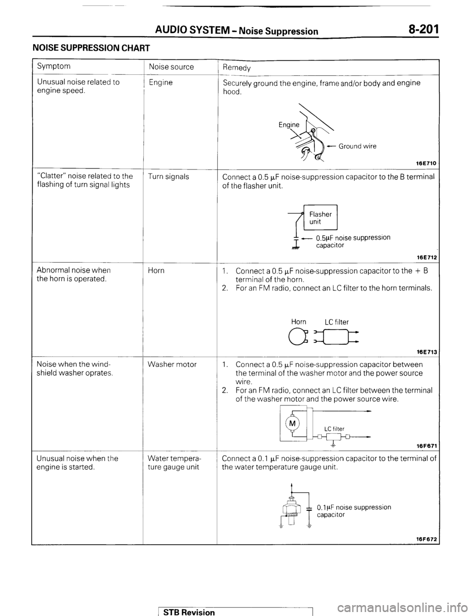
AUDIO SYSTEM - Noise Suppression 8-201
NOISE SUPPRESSION CHART
Symptom
Unusual noise related to
engine speed. ’ Remedy
Securely ground the engine, frame and/or body and engine
hood.
- Ground wire
16E71C
“Clatter” noise related to the
Turn signals
flashing of turn signal lights Connect a 0.5 FF noise-suppression capacitor to the 6 terminal
of the flasher unit.
Abnormal noise when
the horn is operated. Horn ?L - 0.5pF noise suppression
capacitor
16E71:
1. Connect a 0.5 FF noise-suppression capacitor to the + B
terminal of the horn.
2. For an FM radio, connect an LC filter to the horn terminals.
Noise when the wind-
shield washer oprates. Washer motor Horn LC filter
16E71:
1. Connect a 0.5 PF noise-suppression capacitor between
the terminal of the washer motor and the power source
wire.
2. For an FM radio, connect an LC filter between the terminal
of the washer motor and the power source wire.
Unusual noise when the
engine is started. Water tempera-
ture gauge unit Connect a 0.1 p,F noise-suppression capacitor to the terminal o
the water temperature gauge unit.
0.1 PF noise suppression
capacrtor
1 STB Revision
Page 240 of 284
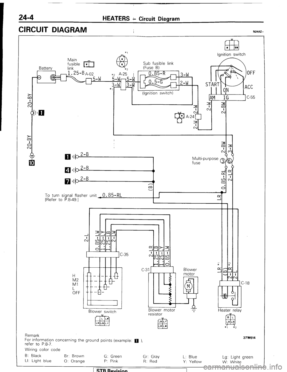
24-4 HEATERS c Circuit Diagram
CIRCUIT DIAGRAM
I
El3 1 El1
lanition switch
Sub fusible link
Battery link m- (Fuse B)
3
1 I (Ignition switch)
Multi-purpose Q
fuse
M $5
LA,:
a3
To turn sional flasher (Init
0.85RI I I f-Y ’ I [Refer to P.8-49.7- - - ‘d -r i
I Blower
Blower switch
CJ -18
Heater r&v Blower motor ?
resistor
Remark
For information concerning the ground points (example:
q ),
refer to P.8-7.
Wiring color code
B: Black Br. Brown
G: Green
Gr: Gray
LI: Light blue
0: Orange P: Pink
R: Red L: Blue
Y: Yellow Lg: Light green
W: White
1 STB Revision
Page 262 of 284
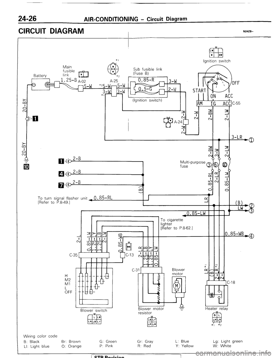
24-26 AIR-CONDITIONING - Circuit Diagram
CIRCUIT DIAGRAM I N24ZB--
Ignition switch
Main
link Sub fusible link
(Fuse B)
I Battery
3
To turn signal flasher unit ~
0.85-RL [Refer to P.8-49.1
i
I 1 ,0.85-LW F
0.85-WB*
“yl lLG1 [Refer to P.8-62.1
C-C
Blower
motor
M
E!! Blower motor
T IA2
Ml
kFF -18
Heater relav N BI ower switch B L
EEJ LR LR resistor
LB LY
El3 LR LI
x’, $2
Wiring color code
B: Black Br: Brown G: Green
Gr: Gray L: Blue Lg: Light green
LI: Light blue 0: Orange P: Pink R: Red
Y: Yellow W: White
/ ST6 Revision