lock MITSUBISHI MONTERO 1987 1.G Owner's Manual
[x] Cancel search | Manufacturer: MITSUBISHI, Model Year: 1987, Model line: MONTERO, Model: MITSUBISHI MONTERO 1987 1.GPages: 284, PDF Size: 14.74 MB
Page 161 of 284
METERS AND GAUGES - Indicators and Warning Lights 8-141
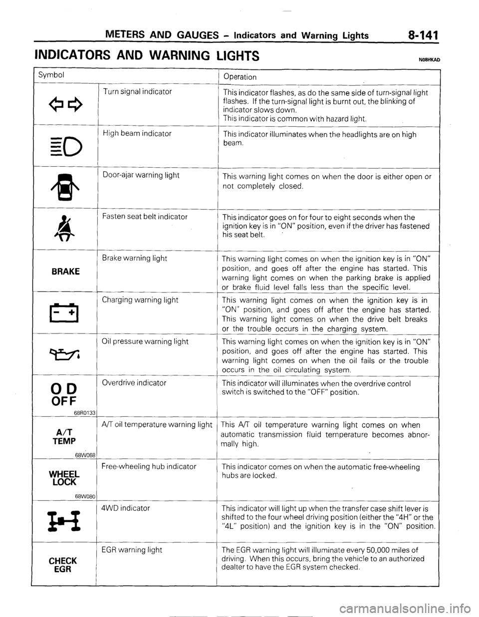
INDICATORS AND WARNING
LIGHTS
Symbol
Operation
Turn signal indicator
+e3 This indicator flashes, as do the same side of turn-signal light
flashes. If the turn-signal light is burnt out, the blinking of
indicator slows down.
This indicator is common with hazard light.
0
High beam indicator
- This indicator illuminates when the headlights are on high
= beam.
=
* Door-ajar warning light
This warning light comes on when the door is either open or
not completely closed.
4 Fasten seat belt indicator
This indicator goes on for four to eight seconds when the
ignition key is in “ON” position, even if the driver has fastened
his seat belt.
BRAKE
Brake warning light
This warning light comes on when the ignition key is in “ON”
position, and goes off after the engine has started. This
warning light comes on when the parking brake is applied
or brake fluid level falls less than the specific level.
III Charging warning light This warning light comes on when the ignition key is in
- + “ON” position, and goes off after the engine has started.
This warning light comes on when the drive belt breaks
or the trouble occurs in the charging system.
Oil pressure warning light This warning light comes on when the ignition key is in “ON”
P position, and goes off after the engine has started. This
warning light comes on when the oil fails or the trouble
occurs in the oil circulating system.
00
Overdrive indicator
This indicator will illuminates when the overdrive control
OFF
switch is switched to the “OFF” position.
68R0133
A/T
A/T oil temperature warning light This A/T oil temperature warning light comes on when
TEMP automatic transmission fluid temperature becomes abnor-
mally high.
68WO68
Free-wheeling hub indicator
YEL This indicator comes on when the automatic free-wheeling
hubs are locked.
68WO80
z4 4WD indicator This indicator will light up when the transfer case shift lever is
shifted to the four wheel driving position (either the “4H” or the
“4L” position) and the ignition key is in the “ON” position.
CHECK
EGR
EGR warning light The EGR warning light will illuminate every 50,000 miles of
driving. When this occurs, bring the vehicle to an authorized
dealter to have the EGR system checked.
) STB Revision
Page 164 of 284
8-144
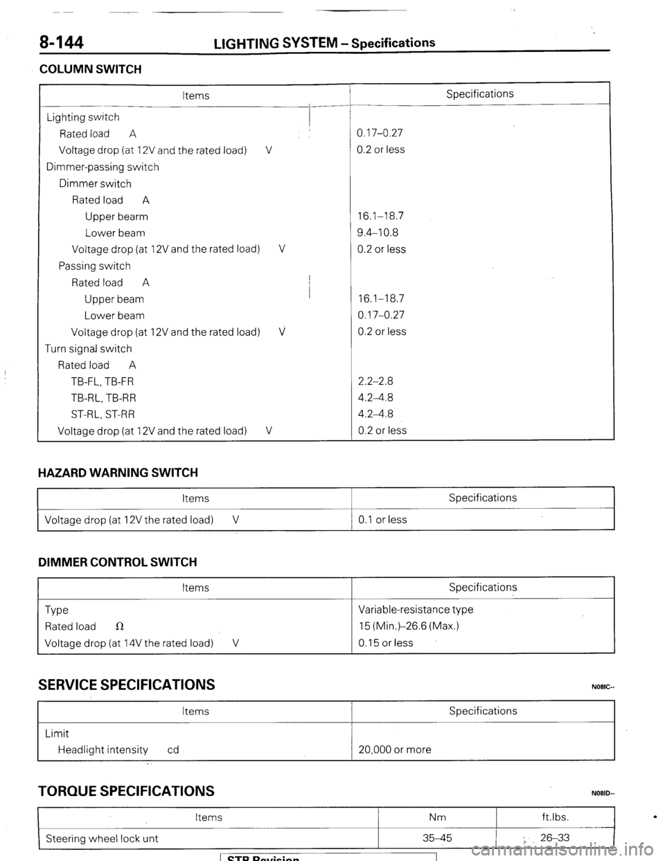
COLUMN SWITCH LIGHTING
SYSTEM -Specifications
Items Specifications
Lighting switch
Rated load A 0.17-0.27
Voltage drop (at 12V and the rated load) V 0.2 or less
Dimmer-passing switch
Dimmer switch
Rated load A
Upper bearm 16.1-18.7
Lower beam 9.4-10.8
Voltage drop (at 12V and the rated load) V 0.2 or less
Passing switch
Rated load A I
Upper beam I
16.1-18.7
Lower beam 0.17-0.27
Voltage drop (at 12V and the rated load)
V 0.2 or less
Turn signal switch
Rated load A
TB-FL, TB-FR 2.2-2.8
TB-RL, TB-R R 4.2-4.8
ST-RL, ST-RR 4.2-4.8
Voltage drop (at 12V and the rated load)
V 0.2 or less
HAZARD WARNING SWITCH
Items Specifications
I Voltage drop (at 12V the rated load) V 0.1 or less
I
DIMMER CONTROL SWITCH
Items Specifications
Type Variable-resistance type
Rated load n 15 (Min.)-26.6 (Max.)
Voltage drop (at 14V the rated load) V 0.15 or less
SERVICE SPECIFICATIONS
Items Specifications
Limit
Headlight intensity cd 20,000 or more
TORQUE SPECIFICATIONS
I
Items Nm ft.lbs.
N08lb
Steering wheel lock unt 35-45 I. 26-33
I
1 STB Revision
Page 184 of 284
8-164 WIPER AND WASHER SYSTEM -Specifications
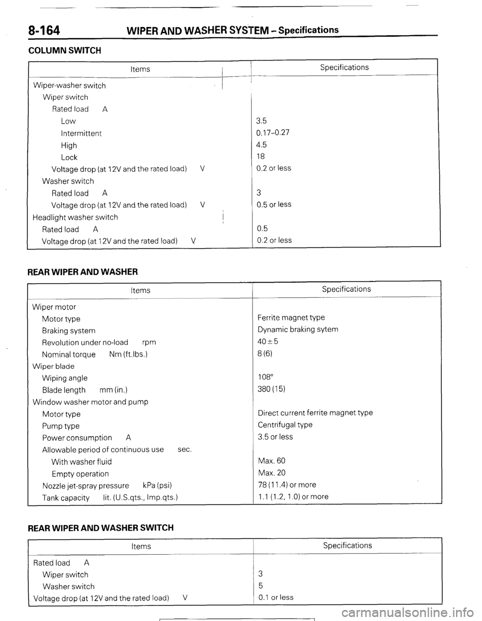
COLUMN SWITCH
L
Specifications
Wiper-washer switch
Wiper switch
Rated load A
Low
intermittent
High
Lock
Voltage drop (at
Washer switch
Rated load A
Voltage drop (at 2V and the rated load) V
2V and the rated load) V
/
Headlight washer switch I
Rated load A
Voltage drop (at 12V and the rated load) V
REAR WIPER AND WASHER
Items
Wiper motor
Motor type
Braking system
Revolution under no-load
m
Nominal torque Nm (ftlbs.)
Wiper blade
Wiping angle
Blade length mm (in.)
Window washer motor and pump
Motor type
Pump type
Power consumption A
Allowable period of continuous use
With washer fluid
Empty operation sec.
Nozzle jet-spray pressure kPa (psi) 78 (11.4) or more
Tank capacity lit. (U.S.qts., Imp.qts.) 1 .I (1.2, 1 .O) or more 3.5
0.17-0.27
4.5
18
0.2 or less
3
0.5 or less
0.5
0.2 or less
Specifications
Ferrite magnet type
Dynamic braking sytem
4025
8 (6)
108
380(15)
Direct current ferrite magnet type
Centrifugal type
3.5 or less
Max. 60
Max. 20
REAR WIPER AND WASHER SWITCH
Items Specifications
Rated load A
Wiper switch 3
Washer switch 5
Voltage drop (at 12V and the rated load) V 0.1 or less
1 STB Revision
Page 185 of 284
WIPER AND WASHER SYSETM - Specifications / Special TOOIS 8-165
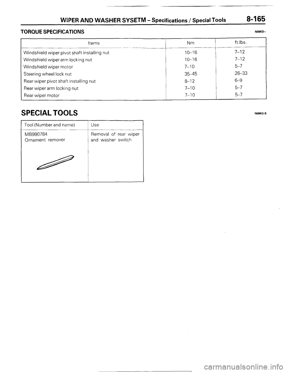
TORQUE SPECIFICATIONS N08KLb-
Items Nm
Windshield wiper pivot shaft installing nut
IO-16 Windshield wiper arm locking nut
IO-16 Windshield wiper motor
7-10 Steering wheel lock nut
35-45 Rear wiper pivot shaft installing nut
8-12 Rear wiper arm locking nut
7-10 Rear wioer motor
7-10
SPECIAL TOOLS NOEKG-B
1 STB Revision
Page 194 of 284
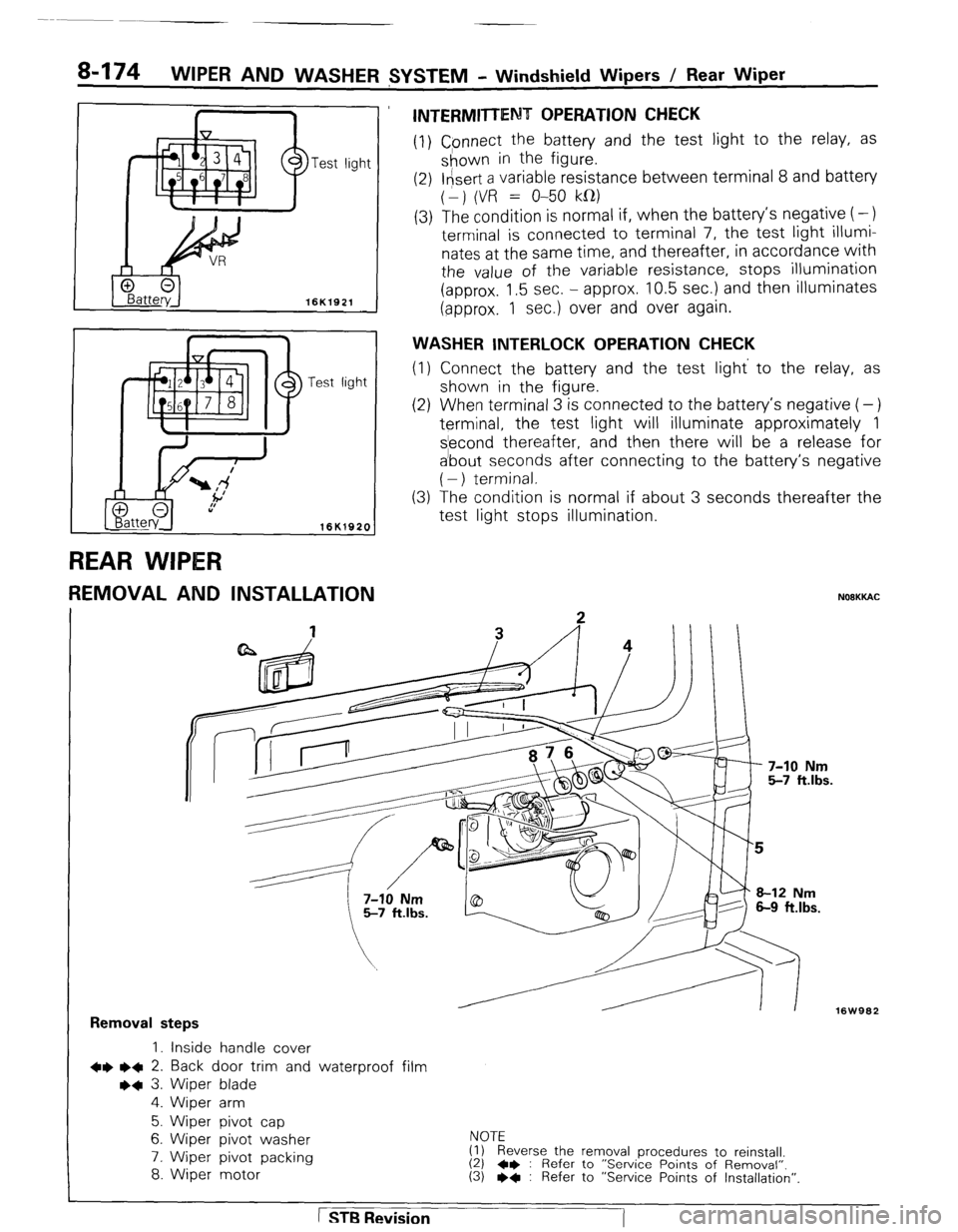
a-174 WIPER AND WASHER $YSTEM - Windshield Wipers / Rear Wiper
REAR WIPtER
7
-est light
16K1920
t
REMOVAL AND INSTALLATION
INTERMITTENT OPERATION CHECK
(1) Cpnnect the battery and the test light to the relay, as
shown in the figure.
(2) l&ert a variable resistance between terminal 8 and battery
(1) (VR = O-50 kfl)
(3) The condition is normal if, when the battery’s negative (-)
terminal is connected to terminal 7, the test light illumi-
nates at the same time, and thereafter, in accordance with
the value of the variable resistance, stops illumination
(approx. 1.5 sec. - approx. 10.5 sec.) and then illuminates
(approx. 1 sec.) over and over again.
WASHER INTERLOCK OPERATION CHECK
(1) Connect the battery and the test light’ to the relay, as
shown in the .figure.
(2) When terminal 3 is connected to the battery’s negative (-)
terminal, the test light will illuminate approximately 1
s’econd thereafter, and then there will be a release for
a’bout seconds after connecting to the battery’s negative
( - ) terminal.
The condition is normal if about 3 seconds thereafter the
test light stops illumination. (3
NOOKKAC
16W962
Removal steps
1. inside handle cover
+e l + 2. Back door trim and waterproof film
++ 3. Wiper blade
4. Wiper arm
5. Wiper pivot cap
6. Wiper pivot washer
7. Wiper pivot packing
8. Wiper motor NOTE
(1) Reverse the removal procedures to reinstall.
(2) 4* : Refer to “Service Points of Removal”. (3) l * : Refer to “Service Points of Installation”.
1 STB Revision
-7
Page 204 of 284
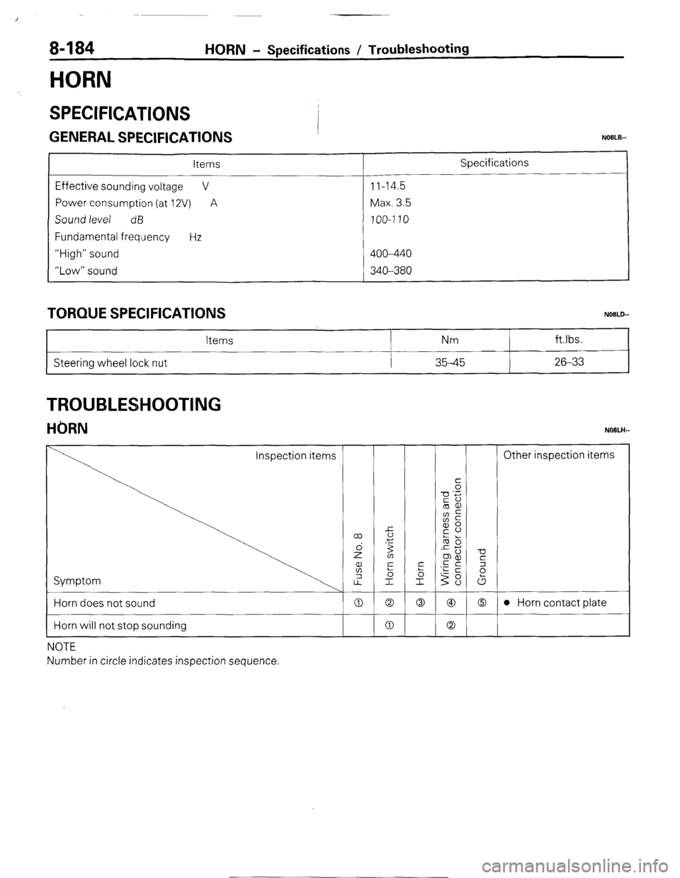
8-184
HORN
HORN - Specifications / Troubleshooting
SPECIFICATIONS
GENERAL SPECIFICATIONS I NOBLE--
Items
Effective sounding voltage V
Power consumption (at 12V) A
Sound level dB
Fundamental frequency Hz
“High” sound
“Low” sound 11-14.5
Max. 3.5
100-7 10
400--440
340--380 Specifications
TORQUE SPECIFICATIONS
Steering wheel lock nut Items
i Nm ft.lbs.
35-45 26-33
TROUBLESHOOTING
HORN NOBLH-
Horn does not sound
Horn will not stop sounding
NOTE
Number in circle indicates inspection sequence. 0 Q 0 @I 0 l Horn contact plate
0 0
1 STB Revision
~-1
Page 208 of 284
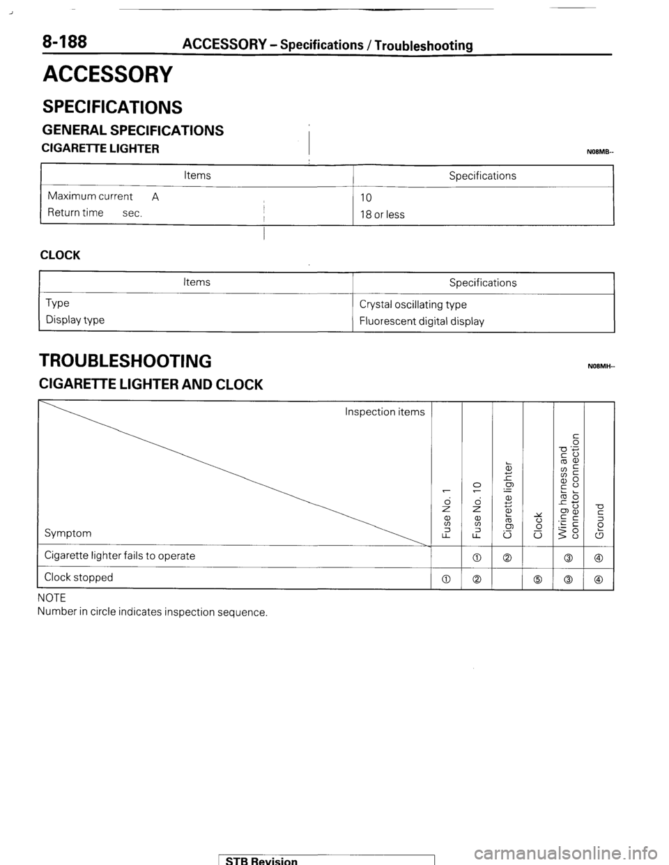
8-188 ACCESSORY - Specifications / Troubleshooting
ACCESSORY
SPECIFICATIONS
GENERAL SPECIFICATIONS
CIGARETTE LIGHTER
I NOBMB-
Items Specifications
Maximum current A
10
Return time
sec. I
I 18 or less
I
CLOCK
Type
Display type Items Specifications
Crystal oscillating type
Fluorescent digital display
TROUBLESHOOTING
ZIGARETTE LIGHTER AND CLOCK
Inspection items
Symptom
Cigarette lighter fails to operate
Clock stopped
NOTE
Number in circle indicates inspection sequence.
MB Revision
Page 209 of 284
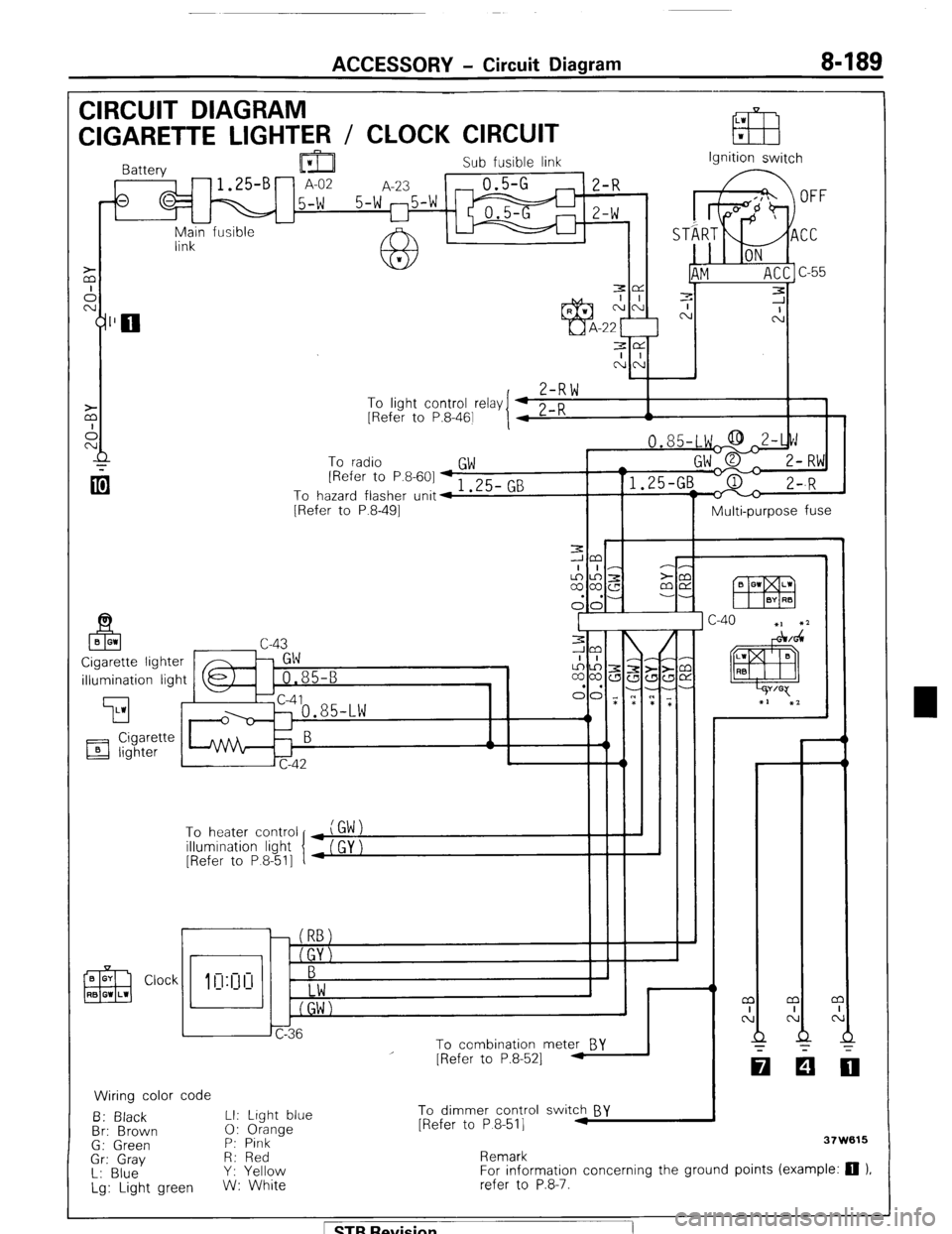
ACCESSORY - Circuit Diagram 8-189
CIRCUIT DIAGRAM
LW
CIGARETTE LIGHTER / CLOCK CIRCUIT EB w
Sub fusible link
,-fs q M 15-W 5-W 25-W m ;I;
I I
-
Main fusible -
link Ignition switch
3e
I I
NN
,
Z-RW To
linht cnntrnl r&v I 4 0 n
I 1 - .J . __._ - -., [Refer to P.8-461
I 4 L-K A
To radio
GW [Refer to P.8-601 + 1 .25- GB
To hazard flasher unit4
[Refer to P.8-491
Multi-purpose fuse
illumination light
’ To heater control
illumination light
[Refer to P 8-511
r
i I
To combination meter BY
Wiring color code
B: Black LI: Light blue
Br: Brown 0: Orange
G: Green P: Pink
Gr: Gray R: Red
L: Blue Y: Yellow
Lg: Light green W: White
I
I - - m
I
N
Q
-
[Refer to P.8-521 -
To dimmer control switch BY
[Refer to P 8-511 .I
Remark 37W615
For information concerning the ground points (example: 0 ).
refer to P.8-7.
1 STB Revision
Page 211 of 284
ACCESSORY - Clock 8-191
CLOCK
REMOVAL AND INSTALLATION NOBMKAD
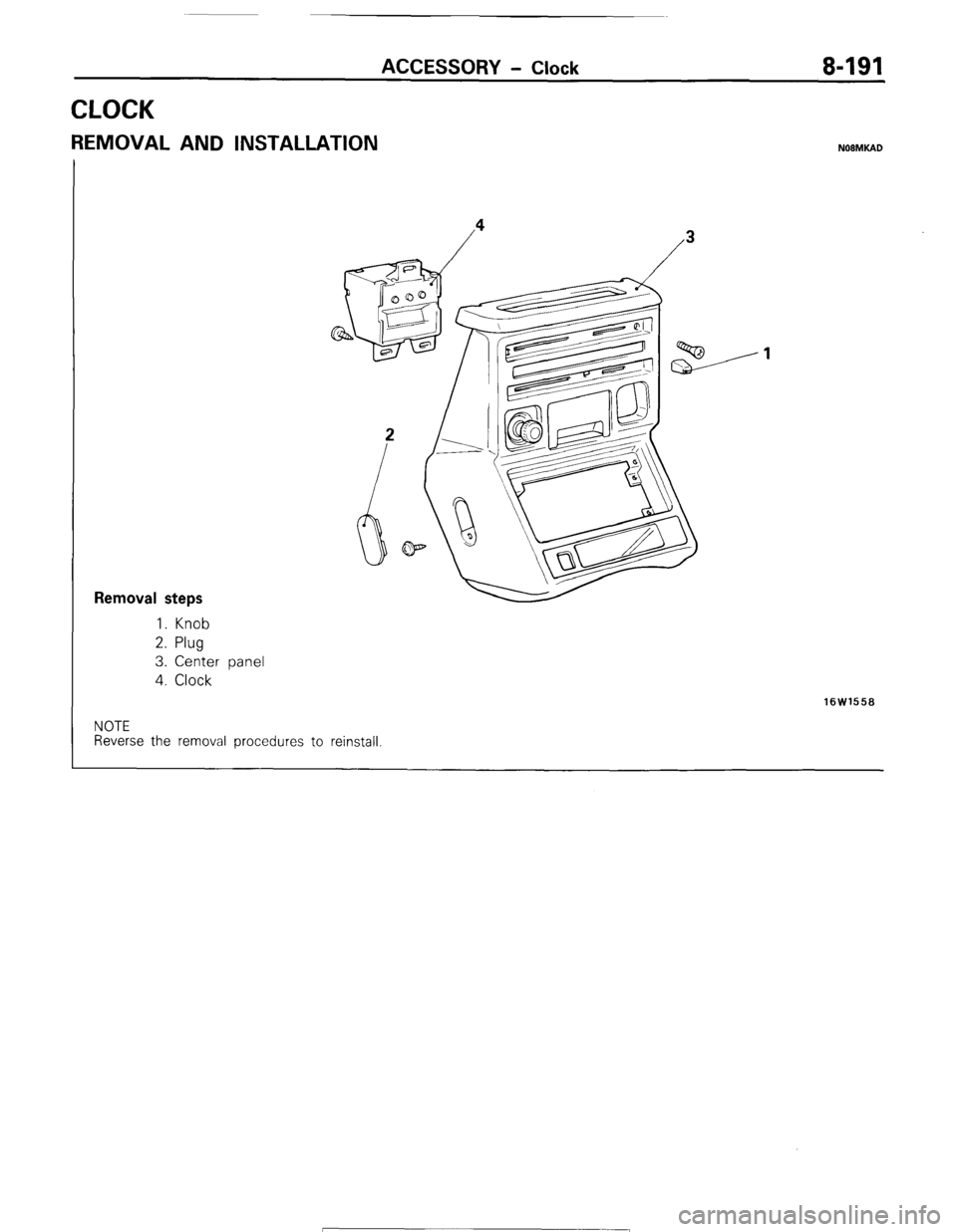
Removal steps
1. Knob
2. Plug
3. Center panel
4. Clock
16W1558
NOTE
Reverse the removal procedures to reinstall 1 STB Revision
Page 216 of 284
8-196 AUDIO SYSTEM - Service Adjustment Procedures
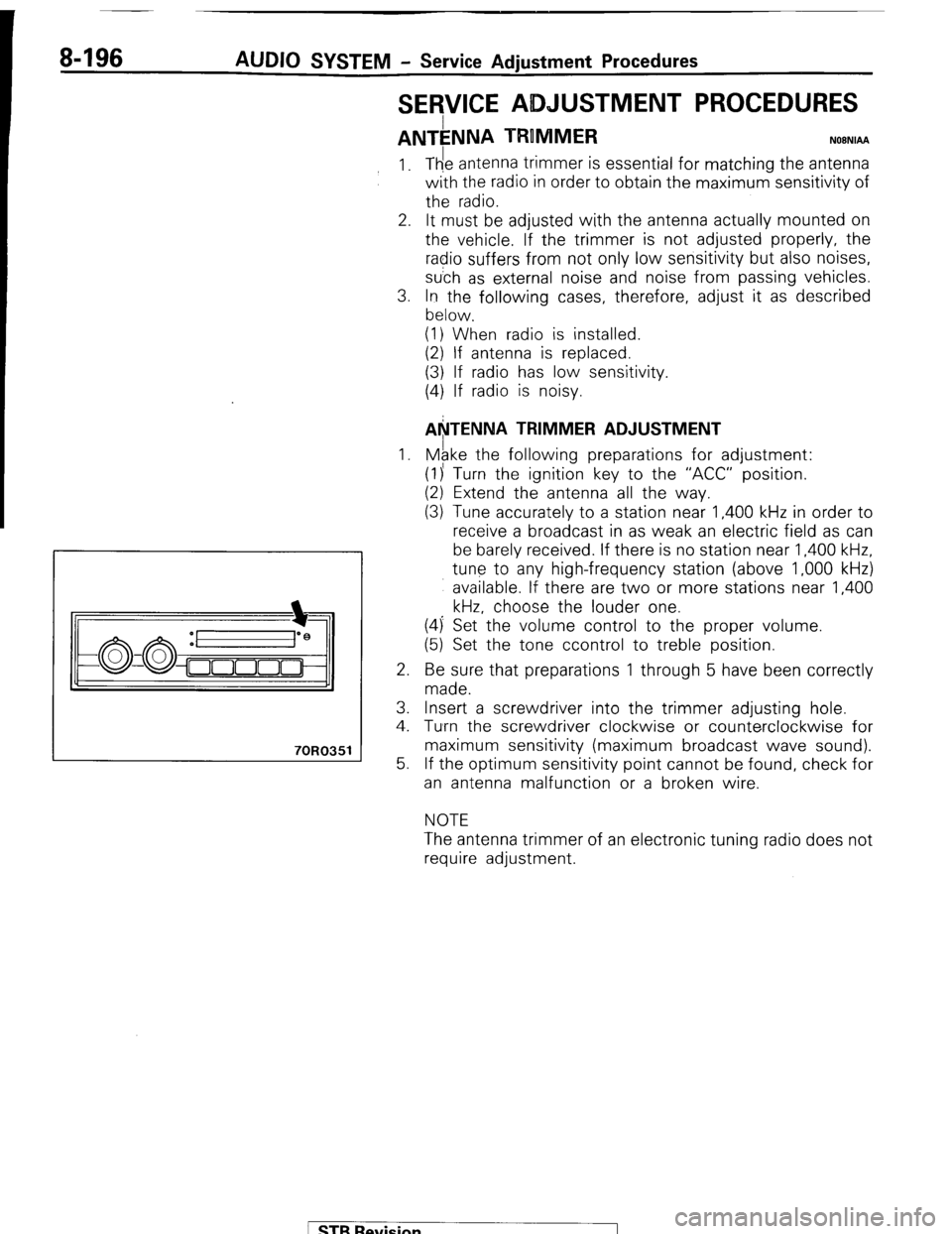
SERVICE ADJUSTMENT PROCEDURES
ANTkNNA TRUMMER NOBNIAA
70R0351
1.
2.
3.
1.
2.
3.
4.
5. The antenna trimmer is essential for matching the antenna
with the radio in order to obtain the maximum sensitivity of
the radio.
It must be adjusted with the antenna actually mounted on
the vehicle. If the trimmer is not adjusted properly, the
radio suffers from not only low sensitivity but also noises,
su’ch as external noise and noise from passing vehicles.
In the following cases, therefore, adjust it as described
below.
(1) When radio is installed.
(2) If antenna is replaced.
(3) If radio has low sensitivity.
(4) If radio is noisy.
AkTENNA TRIMMER ADJUSTMENT
Mgke the following preparations for adjustment:
(1)’ Turn the ignition key to the “ACC” position.
(2) Extend the antenna all the way.
(3) Tune accurately to a station near 1,400 kHz in order to
receive a broadcast in as weak an electric field as can
be barely received. If there is no station near 1,400 kHz,
tune to any high-frequency station (above 1,000 kHz)
available. If there are two or more stations near 1,400
kHz, choose the louder one.
(4) Set the volume control to the proper volume.
(5) Set the tone ccontrol to treble position.
Be sure that preparations 1 through 5 have been correctly
made.
Insert a screwdriver into the trimmer adjusting hole.
Tumrn the screwdriver clockwise or counterclockwise for
maximum sensitivity (maximum broadcast wave sound).
If the optimum sensitivity point cannot be found, check for
an antenna malfunction or a broken wire.
NOTE
The antenna trimmer of an electronic tuning radio does not
require adjustment.
/ STB Revision