specifications MITSUBISHI MONTERO 1987 1.G Owner's Manual
[x] Cancel search | Manufacturer: MITSUBISHI, Model Year: 1987, Model line: MONTERO, Model: MITSUBISHI MONTERO 1987 1.GPages: 284, PDF Size: 14.74 MB
Page 204 of 284
8-184
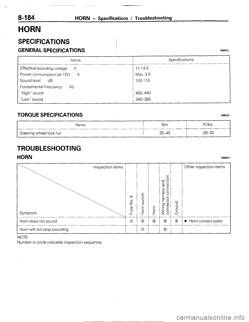
HORN
HORN - Specifications / Troubleshooting
SPECIFICATIONS
GENERAL SPECIFICATIONS I NOBLE--
Items
Effective sounding voltage V
Power consumption (at 12V) A
Sound level dB
Fundamental frequency Hz
“High” sound
“Low” sound 11-14.5
Max. 3.5
100-7 10
400--440
340--380 Specifications
TORQUE SPECIFICATIONS
Steering wheel lock nut Items
i Nm ft.lbs.
35-45 26-33
TROUBLESHOOTING
HORN NOBLH-
Horn does not sound
Horn will not stop sounding
NOTE
Number in circle indicates inspection sequence. 0 Q 0 @I 0 l Horn contact plate
0 0
1 STB Revision
~-1
Page 208 of 284
8-188 ACCESSORY - Specifications / Troubleshooting
ACCESSORY
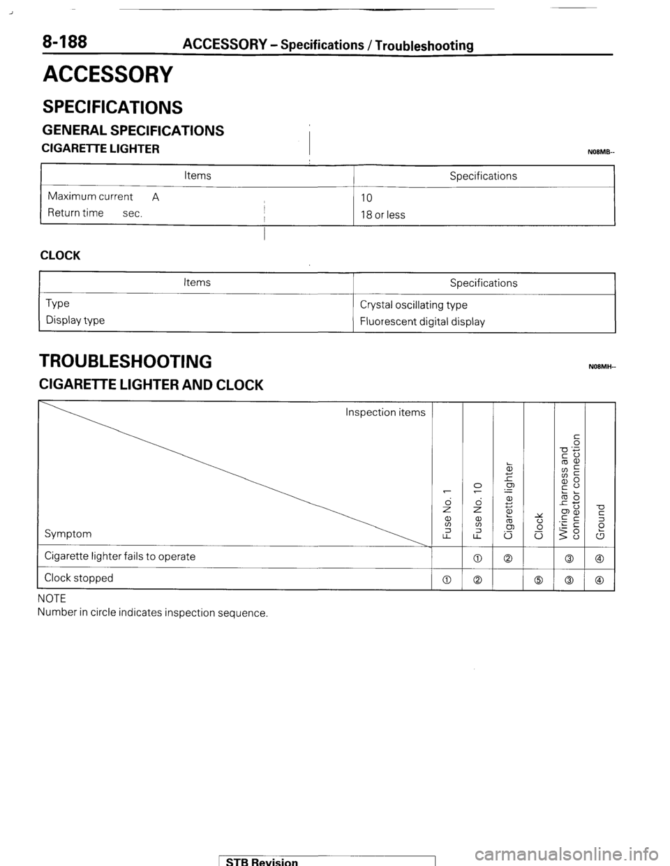
SPECIFICATIONS
GENERAL SPECIFICATIONS
CIGARETTE LIGHTER
I NOBMB-
Items Specifications
Maximum current A
10
Return time
sec. I
I 18 or less
I
CLOCK
Type
Display type Items Specifications
Crystal oscillating type
Fluorescent digital display
TROUBLESHOOTING
ZIGARETTE LIGHTER AND CLOCK
Inspection items
Symptom
Cigarette lighter fails to operate
Clock stopped
NOTE
Number in circle indicates inspection sequence.
MB Revision
Page 212 of 284
8-192 AUDIO SYSTEM - Specifications
AUDIO SYSTEM I
/
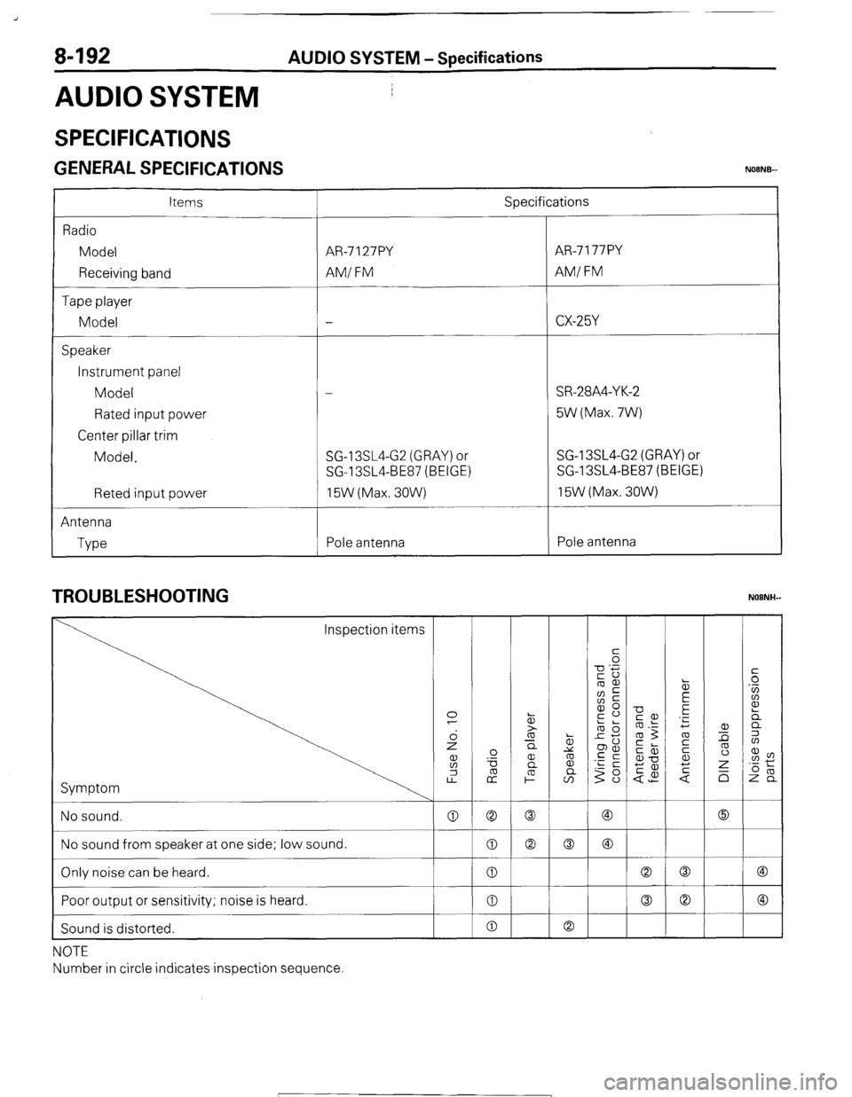
SPECIFICATIONS
GENERAL SPECIFICATIONS NOENB-
Items
Radio
Model
Receiving band
Tape player
Model
Speaker
Instrument panel
Model
Rated input power
Center pillar trim
Model.
Reted input power
Antenna
Type Spe,cifications
AR-7 127PY AR-7 177PY
AM/ FM AMI FM
-
CX-25Y
-_-
-
SR-28A4-Y K-2
5W (Max. 7W)
SG-13SL4-G2 (GRAY) or SG-13SL4-G2 (GRAY) or
SG-13SL4-BE87 (BEIGE) SG-13SL4-BE87 (BEIGE)
15W (Max. 30W) 15W (Max. 3OW)
Pole antenna Pole antenna
TROUBLESHOOTING
Symptom
NOTE
Number in circle indicates inspection sequence
( STB Revision
Page 213 of 284
AUDIO SYSTEM - Specifications 8-193
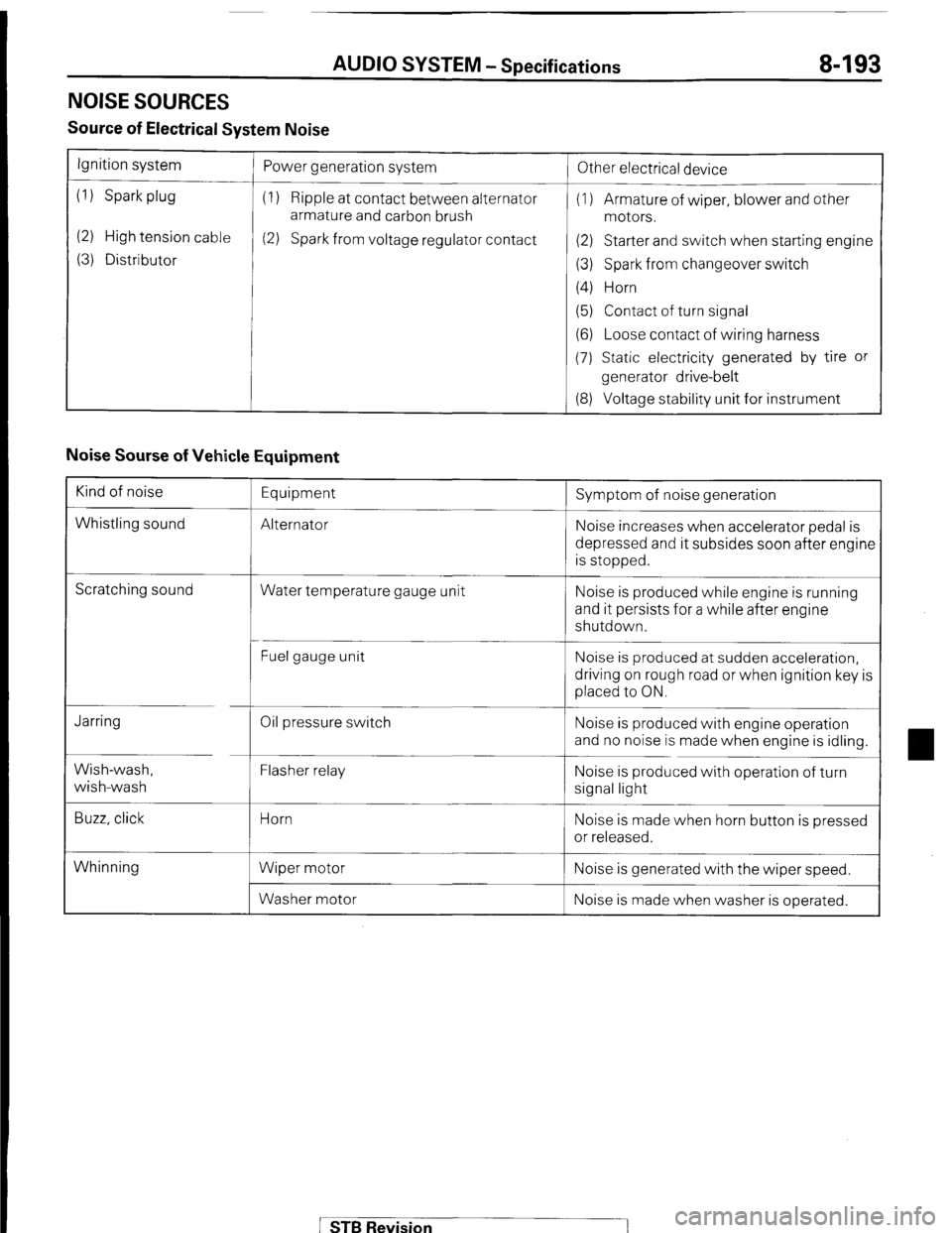
NOISE SOURCES
Source of Electrical System Noise
Ignition system
(1) Spark plug
(2) High tension cable
(3) Distributor Power generation system
(1) Ripple at contact between alternator
armature and carbon brush
(2) Spark from voltage regulator contact
!
Other electrical device
(1) Armature of wiper, blower and other
motors.
(2) Starter and switch when starting engine
(3) Spark from changeover switch
(4) Horn
(5) Contact of turn signal
(6) Loose contact of wiring harness
(7) Static electricity generated by tire or
generator drive-belt
(8) Voltage stability unit for instrument
Noise Sourse of Vehicle Equipment
Kind of noise
Whistling sound Equipment
Alternator Symptom of noise generation
Noise increases when accelerator pedal is
depressed and it subsides soon after engine
is stopped.
Scratching sound
Water temperature gauge unit Noise is produced while engine is running
and it persists for a while after engine
shutdown.
Fuel gauge unit Noise is produced at sudden acceleration,
driving on rough road or when ignition key is
placed to ON.
Jarring
Wish-wash,
wish-wash
Buzz, click Oil pressure switch
Flasher relay
Horn
Wiper motor
Washer motor Noise is produced with engine operation
and no noise is made when engine is idling.
Noise is produced with operation of turn
signal light
Noise is made when horn button is pressed
or released.
Whinning Noise is generated with the wiper speed.
Noise is made when washer is operated.
STB Revision
Page 223 of 284
BACK DOOR WINDOW DEFOGGER - Specifications / Special Tools
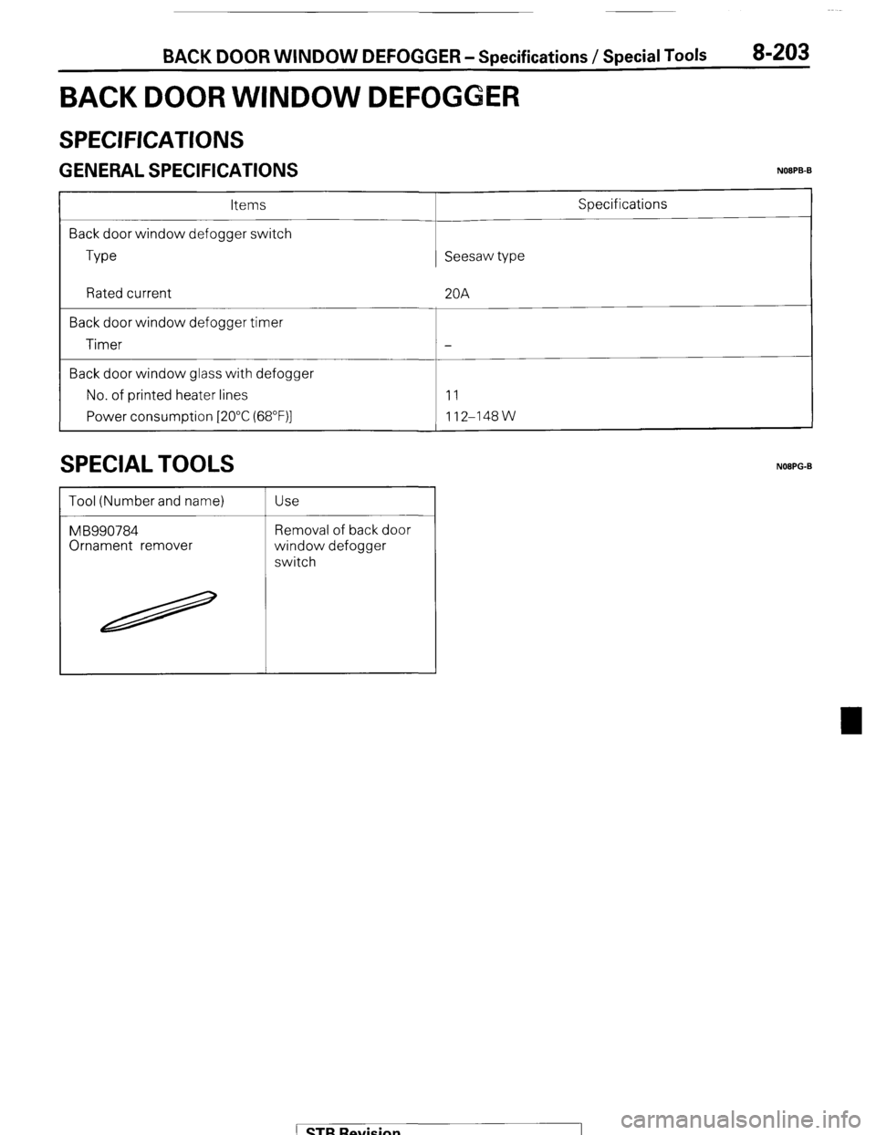
BACK DOOR WINDOW DEFOGGER
8-203
SPECIFICATIONS
( ;ENERAL SPECIFICATIONS NOOPB-B
Items
Back door window defogger switch
Type Seesaw type Specifications
Rated current
Back door window defogger timer
Timer
Back door window glass with defogger
No. of printed heater lines
Power consumption [2O”C (68”F)] 20A
-
11
112-148W
SPECIAL TOOLS
Tool (Number and name)
MB990784
Ornament remover Use
Removal of back door
window defogger
switch
NOBPG-B
1 STB Revision
Page 232 of 284
8-212 AUTOMATIC FREE-WHEELING HUB lNCDlCATOR SYSTEM - $%%60n’~at’on’
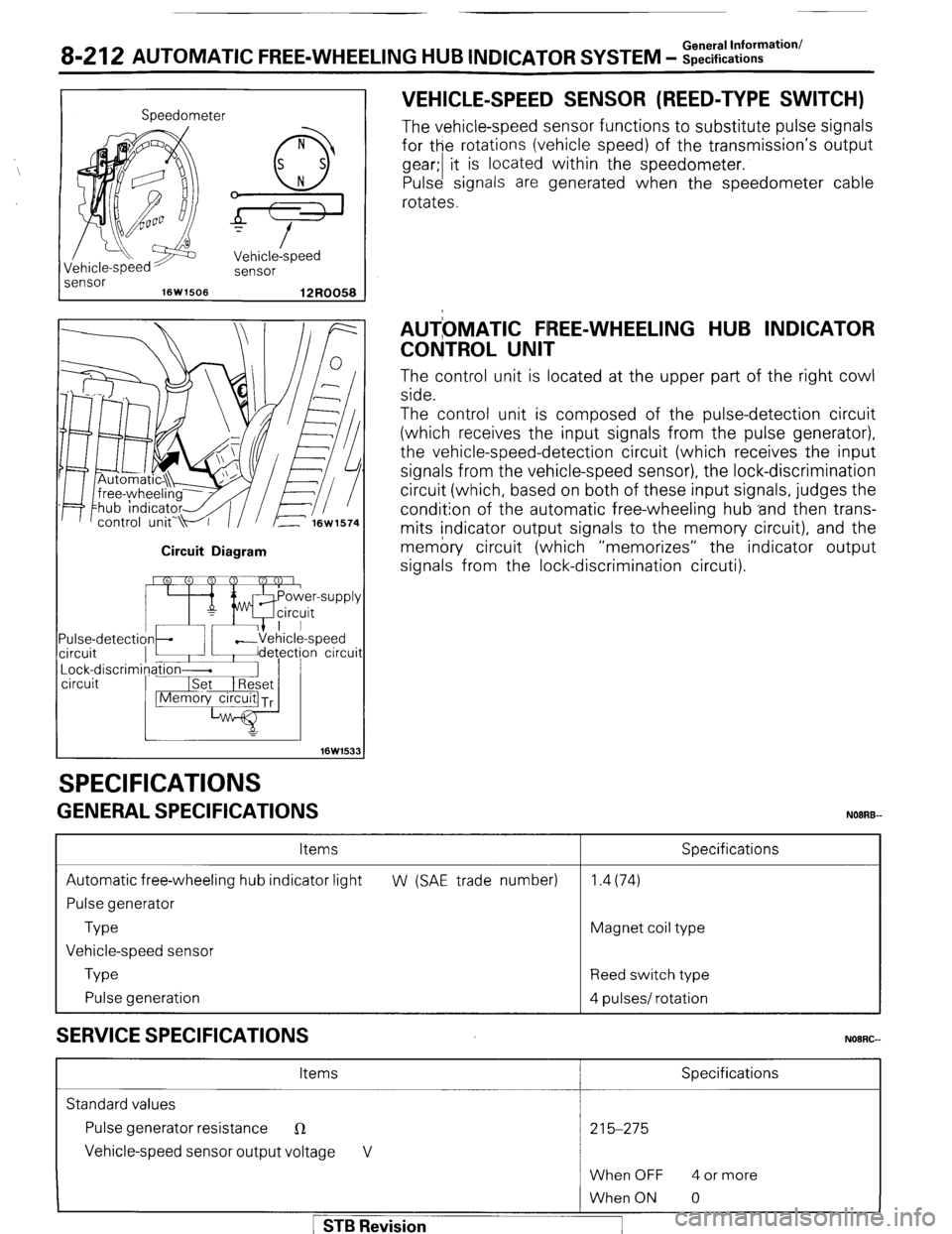
Speedometer
I
iensor Vehicle-speed
sensor
16W1506
12R0058
Circuit Diagram
16W153
SPECIFICATIONS
GENERAL SPECIFICATIONS VEHICLE-SPEED SENSOR (REED-TYPE SWITCH)
The vehicle-speed sensor functions to substitute pulse signals
for the rotations (vehicle speed) of the transmission’s output
gear;/ t i is located within the speedometer.
Pulse signals are generated when the speedometer cable
rotates.
AUTbMATlC FREE-WHEELING HUB INDICATOR
CONTROL UNIT
The control unit is located at the upper part of the right cowl
side.
The control unit is composed of the pulse-detection circuit
(which receives the input signals from the pulse generator),
the vehicle-speed-detection circuit (which receives the input
signals from the vehicle-speed sensor), the lock-discrimination
circuit (which, based on both of these input signals, judges the
condition of the automatic free-wheeling hub ‘and then trans-
mits indicator output signals to the memory circuit), and the
memory circuit (which “memorizes” the indicator output
signals from the lock-discrimination circuti).
Items
Automatic free-wheeling hub indicator light
Pulse generator
Type
Vehicle-speed sensor
Type
Pulse generation
SERVICE SPECIFICATIONS
Specifications
W (SAE trade number) 1.4(74)
Magnet coil type
Reed switch type
4 pulses/ rotation
NOORG-
Items Specifications
Standard values
Pulse generator resistance
R 215-275
Vehicle-speed sensor output voltage V
When OFF 4 or more 1 STB Revision
When ON 0
Page 237 of 284
24-1
AIR-CO IONING
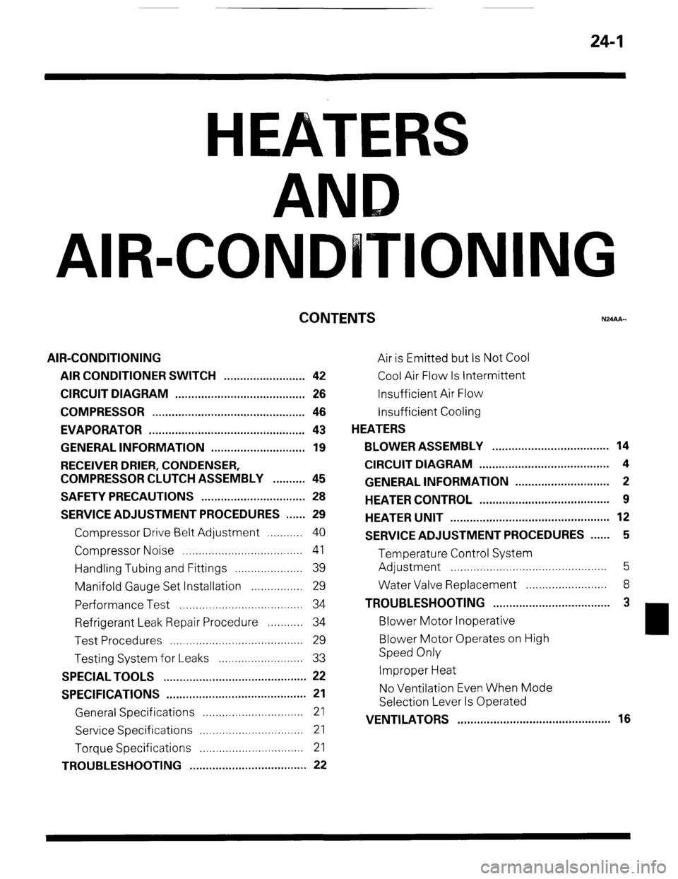
CONTENTS
AIR-CONDITIONING
AIR CONDITIONER SWITCH ......................... 42
CIRCUIT DIAGRAM ...................................... . . 26
COMPRESSOR ............................................... 46
EVAPORATOR ............................................ . ... 43
GENERAL INFORMATION .............. . ....... . . . .... 19
RECEIVER DRIER, CONDENSER,
COMPRESSOR CLUTCH ASSEMBLY .......... 45
SAFETY PRECAUTIONS ................................ 28
SERVICE ADJUSTMENT PROCEDURES ...... 29
Compressor Drive Belt Adjustment ...........
40
Compressor Noise ..................................... 41
Handling Tubing and Fittings ..................... 39
Manifold Gauge Set Installation ................ 29
Performance Test ...................................... 34
Refrigerant Leak Repair Procedure ........... 34
Test Procedures ......................................... 29
Testing System for Leaks .......................... 33
SPECIAL TOOLS ............................................ 22
SPECIFICATIONS ...... . .
.. . ................................ 21
General Specifications ...............................
21
Service Specifications ................................
21
Torque Specifications ................................
21
TROUBLESHOOTING .................................... 22 Air is Emitted but Is Not Cool
Cool Air Flow Is Intermittent
Insufficient Air Flow
Insufficient Cooling
HEATERS
BLOWER ASSEMBLY . . . . . . . . . . . . . . . . . . ..a............... 14
CIRCUIT DIAGRAM . . . . . . . . . . . . . . . . . . . . . . . . . . . . . . . . . . . . . . . . 4
GENERAL INFORMATION . . . . . . . . . . . . . . . . . . . . . . . . . . . . . 2
HEATER CONTROL . . . . . . . . . . . . . . . . . . . . . . . . . . . . . . . . . . . . . . . . 9
HEATER UNIT . . . . . . . . . . . . . . . . . . . . . . . . . . . . . . . . . . . . . . . . . . . . . . . . . 12
SERVICE ADJUSTMENT PROCEDURES . . . . . . 5
Temperature Control System
Adjustment . . . . . . . . . . . . . . . . . . . . . . . . . . . . . . . . . . . . . . . . . . . . . . . . 5
Water Valve Replacement . . . . . . . . . . . . . . . . . . . . . . . 8
TROUBLESHOOTING . . . . . . . . . . . . . . . . . . . . . . . . . . . . . . . . . . . . 3
Blower Motor Inoperative
Blower Motor Operates on High
Speed Only
Improper Heat
No Ventilation Even When Mode
Selection Lever Is Operated
VENTILATORS . . . . . . . . . . . . . . . . . . . . . . . . . . . ..a..... . . . . . . . . . . . .
16
Page 257 of 284
AIR-CONDITIONING -Specifications
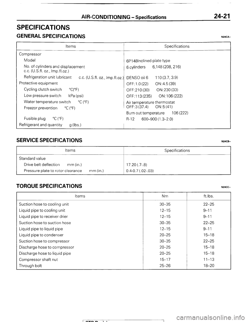
SPECIFICATIONS
GENERAL SPECIFICATIONS
24-2 1
N24CA-
Items Specifications
Compressor
Model
6P148lnclined-plate type
No. of cylinders and displacement
6 cylinders 6,148 (208,216)
cc. (U.S.fl. oz., Imp.fl.02.)
Refrigeration unit lubricant
cc. (U.S.fl. oz., Imp.fl.oz.) DENS0 oil 6 110 (3.7,3.9)
Protective equipment
OFF: 1 .O (22) ON:4.5 (39)
Cycling clutch switch
“C(“F)
OFF:210 (30) ON:230 (33)
Low pressure switch
kPa (psi)
OFF: 113 (235) ON:106(222)
Water temperature switch
“C (“F)
Air temperature thermostat
Freezor prevention
“C (“F) OFF:3 (37.4) ON:5 (41)
Burn out temperature 106 (222)
Fusible plug “C (“F)
R-l 2 600-900 (1.3-2.0)
Refrigerant and quantity
g (Ibs.1
SERVICE SPECIFICATIONS N24CE-
Items Specifications
Standard value
Drive belt deflection mm (in.) 17.20 (.7-.8)
Pressure plate to rotor clearance mm (in.)
0.4-0.7 (.02-.03)
TORQUE SPECIFICATIONS N24CG Items Nm ftlbs.
Suction hose to cooling unit 30-35 22-25
Liquid pipe to cooling unit 12-15 9-l 1
Liquid pipe to receiver drier 12-15 9-l 1
Suction hose to suction hose 30-35 22-25
Liquid pipe to liquid pipe 12-15 9-l 1
Liquid pipe to condenser 20-25 15-18
Suction hose to compressor 30-35 22-25
Discharge hose to compressor 20-25 15-18
Discharge hose to liquid pipe 20-25 15-18
Compressor shaft nut 15-17 11-13
Through bolt 25-26 18-20
/ STB Revision I