engine MITSUBISHI MONTERO 1987 1.G Owner's Guide
[x] Cancel search | Manufacturer: MITSUBISHI, Model Year: 1987, Model line: MONTERO, Model: MITSUBISHI MONTERO 1987 1.GPages: 284, PDF Size: 14.74 MB
Page 152 of 284
8-132 METERS AND GAUGES - Service Adjustment Procedures
(5) If both the test light and gauge operate, the circuit to the
gauge unit is normal and the gauge unit itself is faulty.
If the test light flashes but the gauge does not operate, the
gauge is faulty.
If 1 neither the test light nor the gauge operates, the water
temperature gauge circuit is faulty.
Se
VVATER TEMPERATURE GAUGE UNIT ONSPEC-
TION
NOBHIKD
To check the water temperature gauge unit, first remove it
from the intake manifold.
For detailed information concerning installation of the water
temperature gauge unit, refer to GROUP 11, INTAKE AND
EXHAUST SYSTEM - Intake Manifold.
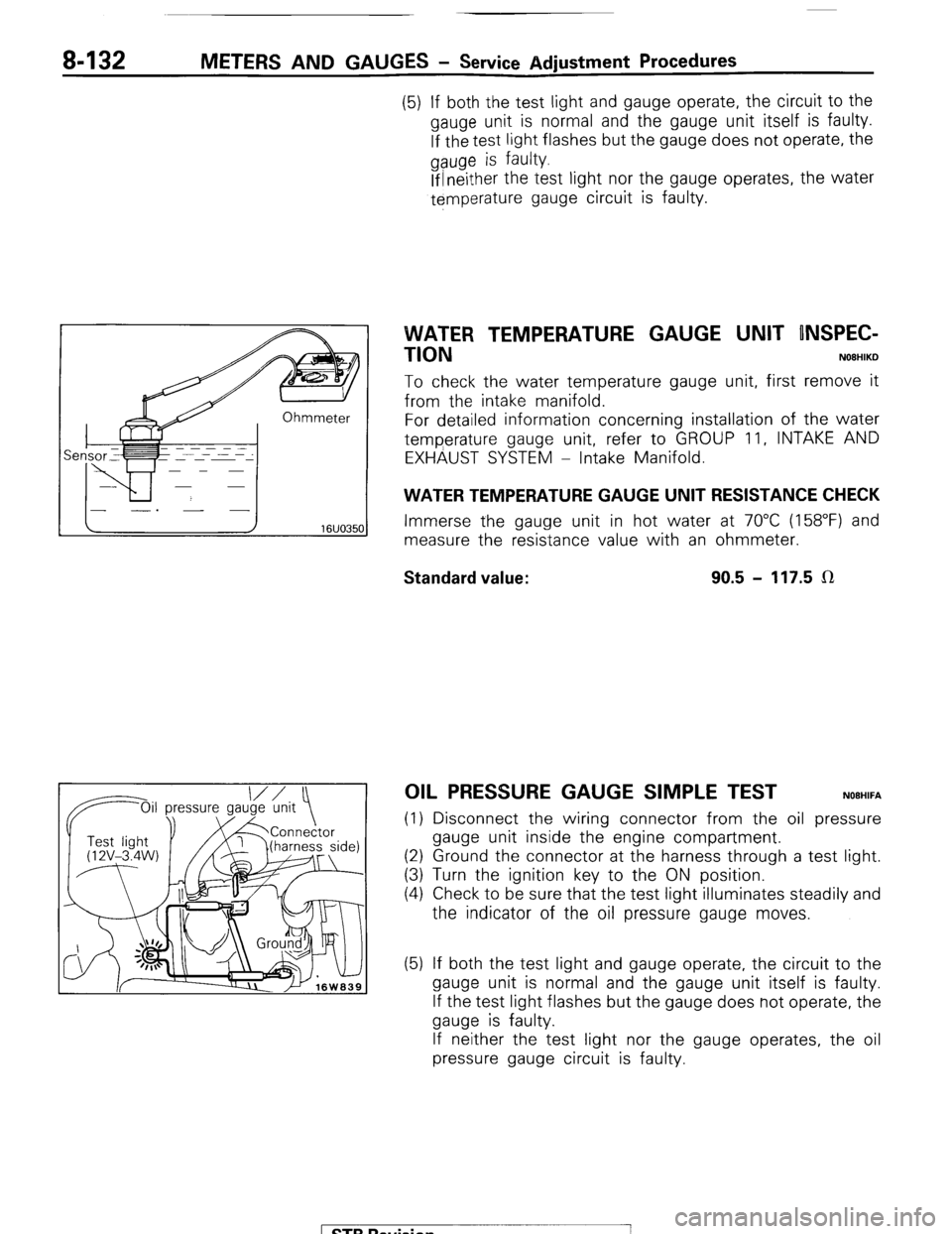
WATER TEMPERATURE GAUGE UNIT RESISTANCE CHECK
Immerse the gauge unit in hot water at 70°C (158°F) and
measure the resistance value with an ohmmeter.
Standard value: 90.5 - 117.5 LR
OIL PRESSURE GAUGE SIMPLE TEST NOEHIFA
(1) Disconnect the wiring connector from the oil pressure
gauge unit inside the engine compartment.
(2) Ground the connector at the harness through a test light.
(3) Turn the ignition key to the ON position.
(4) Check to be sure that the test light illuminates steadily and
the indicator of the oil pressure gauge moves.
(5) If both the test light and gauge operate, the circuit to the
gauge unit is normal and the gauge unit itself is faulty.
If the test light flashes but the gauge does not operate, the
gauge is faulty.
If neither the test light nor the gauge operates, the oil
pressure gauge circuit is faulty.
1 STB Revision
-7
Page 153 of 284
METERS AND GAUGES - Service Adjustment Procedures 8-133
IOil p Oil pressure ressure
gauge unit
1 I Test light
‘@‘(12V - 3.4 I
W)
16W1576
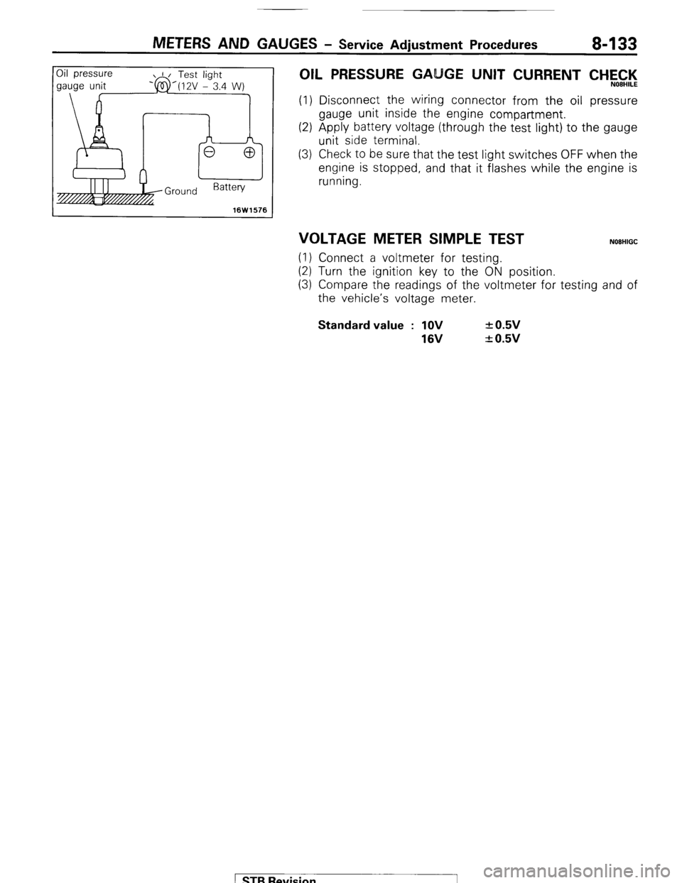
OIL PRESSURE GA GE UNIT CURRENT CHEC,‘l<,
(1) Disconnect the wiring connector from the oil pressure
gauge unit inside the engine compartment.
(2) Apply battery voltage (through the test light) to the gauge
unit side terminal.
(3) Check to be sure that the test light switches OFF when the
engine is stopped, and that it flashes while the engine is
running.
VOLTAGE METER SIMPLE TEST NOEHIGC
(1) Connect a voltmeter for testing.
(2) Turn the ignition key to the ON position.
(3) Compare the readings of the voltmeter for testing and of
the vehicle’s voltage meter. Standard value : 1OV
16V + 0.5v
+ 0.5v
1 STB Revision
Page 161 of 284
METERS AND GAUGES - Indicators and Warning Lights 8-141
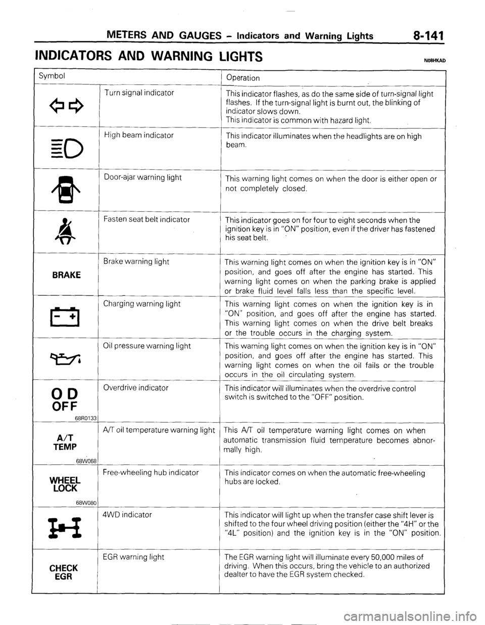
INDICATORS AND WARNING
LIGHTS
Symbol
Operation
Turn signal indicator
+e3 This indicator flashes, as do the same side of turn-signal light
flashes. If the turn-signal light is burnt out, the blinking of
indicator slows down.
This indicator is common with hazard light.
0
High beam indicator
- This indicator illuminates when the headlights are on high
= beam.
=
* Door-ajar warning light
This warning light comes on when the door is either open or
not completely closed.
4 Fasten seat belt indicator
This indicator goes on for four to eight seconds when the
ignition key is in “ON” position, even if the driver has fastened
his seat belt.
BRAKE
Brake warning light
This warning light comes on when the ignition key is in “ON”
position, and goes off after the engine has started. This
warning light comes on when the parking brake is applied
or brake fluid level falls less than the specific level.
III Charging warning light This warning light comes on when the ignition key is in
- + “ON” position, and goes off after the engine has started.
This warning light comes on when the drive belt breaks
or the trouble occurs in the charging system.
Oil pressure warning light This warning light comes on when the ignition key is in “ON”
P position, and goes off after the engine has started. This
warning light comes on when the oil fails or the trouble
occurs in the oil circulating system.
00
Overdrive indicator
This indicator will illuminates when the overdrive control
OFF
switch is switched to the “OFF” position.
68R0133
A/T
A/T oil temperature warning light This A/T oil temperature warning light comes on when
TEMP automatic transmission fluid temperature becomes abnor-
mally high.
68WO68
Free-wheeling hub indicator
YEL This indicator comes on when the automatic free-wheeling
hubs are locked.
68WO80
z4 4WD indicator This indicator will light up when the transfer case shift lever is
shifted to the four wheel driving position (either the “4H” or the
“4L” position) and the ignition key is in the “ON” position.
CHECK
EGR
EGR warning light The EGR warning light will illuminate every 50,000 miles of
driving. When this occurs, bring the vehicle to an authorized
dealter to have the EGR system checked.
) STB Revision
Page 162 of 284
8-142 METERS AND GAUGES - EGR Warning System
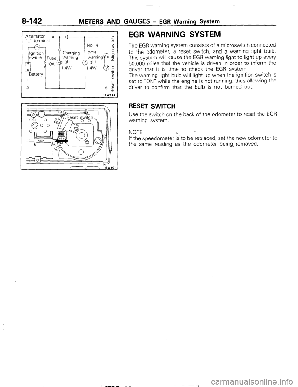
EGR WARNING SYSTEM
The EGR warning system consists of a microswitch connected
to the odometer, a reset switch, and a warning light bulb.
This system will cause the EGR warning light to light up every
50,000 miles that the vehicle is driven in order to inform the
driver that it is time to check the EGR system.
The warning light bulb will light up when the ignition switch is
set to “ON” while the engine is not running, thus allowing the
driver to confirm that the bulb is not burned out.
RESET SWITCH
Use the switch on the back of the odometer to reset the EGR
warning system.
NOTE
If the speedometer is to be replaced, set the new odometer to
the same reading as the odometer being, removed.
1 STB Revision
Page 177 of 284
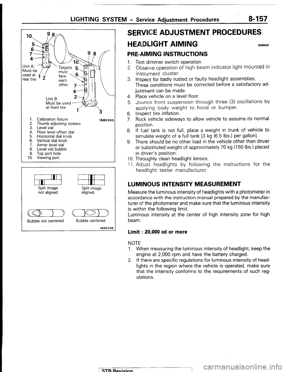
LIGHTING SYSTEM - Service Adjustment Procedures 8-157
Must be used J;it A:
I ‘w ‘Targets
1. Calibration fixture
2. Thumb adjusting screws
3. Level vial
4. Floor level offset dial
5. Horizontal dial knob
6. Vertical dial knob
7. Aimer level vial
8. Level vial bubble
9. Top port hole
10. Viewing port
1660245
Split image
not aligned Split image
aligned
Bubble not centered Bubble centered
1660246
E ADJUSTMENT PROCEDURES
T AIMING
PRE-AIMING INSTRUCTIONS 1. Test dimmer switch operation.
2. Observe operation of high beam indicator light
mounted in instrument cluster.
3. Inspect for badly rusted or faulty headlight assemblies.
These conditions must be corrected before a satisfactory ad-
justment can be made.
4. Place vehicle on a level floor.
5. Jounce front suspension through three (3) oscillations by
applying body weight to hood or bumper.
6. Inspect tire inflation.
7. Rock vehicle sideways to allow vehicle to assume its normal
position.
8. If fuel tank is not full, place a weight in trunk of vehicle to
simulate weight of a full tank [3 kg (6.5 Ibs.) per gallon].
9. There should be no other load in the vehicle other than driver
or substituted weight of approximately 70 kg (150 Ibs.) placed
in driver’s position.
10. Throughly clean headlight lenses.
11. Adjust headlights by following the instructions for the
headlight tester manufacturer.
LUMINOUS INTENSITY MEASUREMENT Measure the luminous intensity of headlights with a photometer in
accordance with the instruction manual prepared by the manufac-
turer of the photometer and make sure that the luminous intensity
is within the following limit.
Luminous intensity at the center of high intensity zone for high
beam.
Limit : 20,000 cd or more NOTE
1. When measuring the luminous intensity of headlight, keep the
engine at 2,000 rpm and have the battery charged.
2. If there are specific regulations for luminous intensity of head-
lights in the region where the vehicle is operated, make sure
that the intensity conforms to the requirements of such reg-
ulations.
pTB Revision
Page 213 of 284
AUDIO SYSTEM - Specifications 8-193
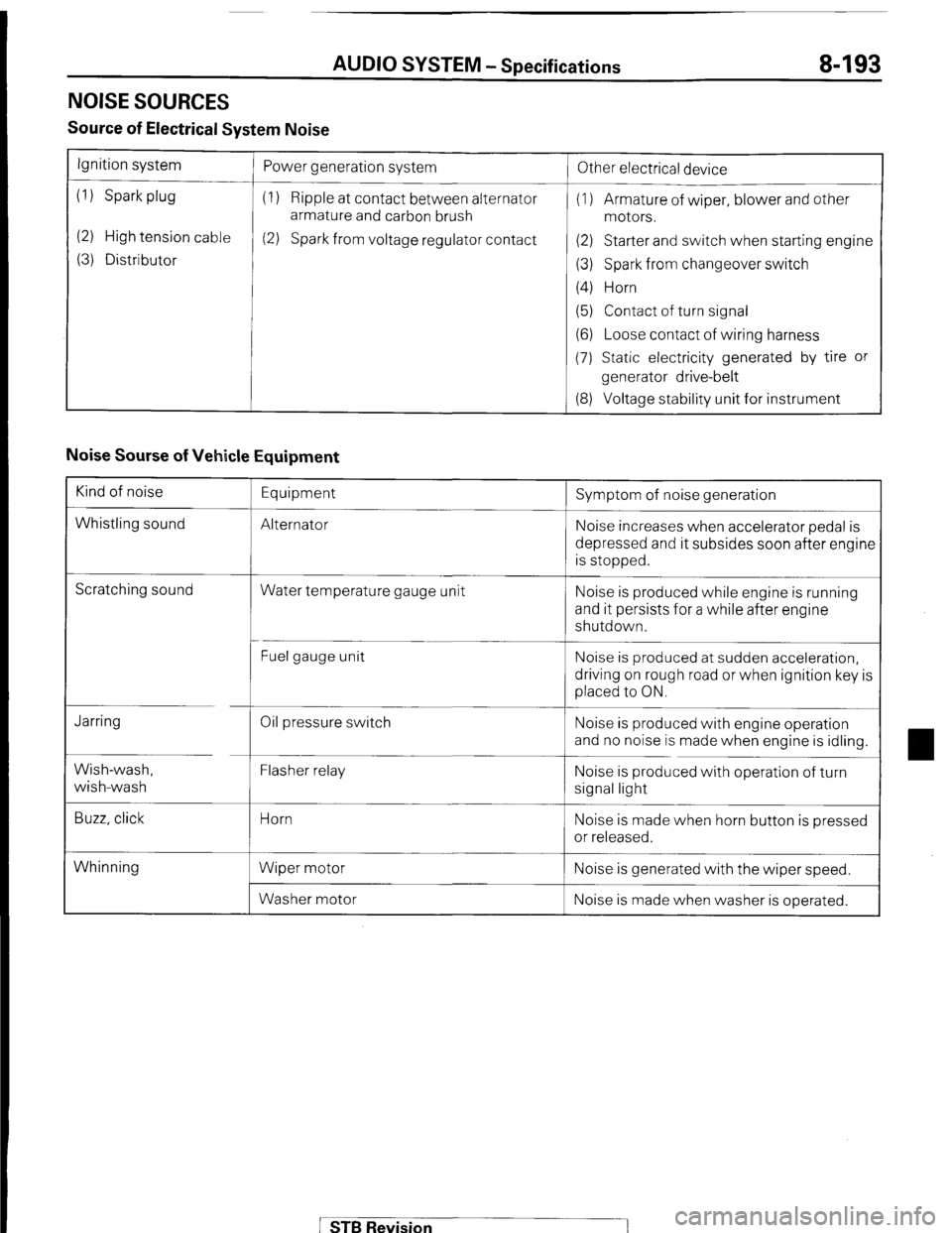
NOISE SOURCES
Source of Electrical System Noise
Ignition system
(1) Spark plug
(2) High tension cable
(3) Distributor Power generation system
(1) Ripple at contact between alternator
armature and carbon brush
(2) Spark from voltage regulator contact
!
Other electrical device
(1) Armature of wiper, blower and other
motors.
(2) Starter and switch when starting engine
(3) Spark from changeover switch
(4) Horn
(5) Contact of turn signal
(6) Loose contact of wiring harness
(7) Static electricity generated by tire or
generator drive-belt
(8) Voltage stability unit for instrument
Noise Sourse of Vehicle Equipment
Kind of noise
Whistling sound Equipment
Alternator Symptom of noise generation
Noise increases when accelerator pedal is
depressed and it subsides soon after engine
is stopped.
Scratching sound
Water temperature gauge unit Noise is produced while engine is running
and it persists for a while after engine
shutdown.
Fuel gauge unit Noise is produced at sudden acceleration,
driving on rough road or when ignition key is
placed to ON.
Jarring
Wish-wash,
wish-wash
Buzz, click Oil pressure switch
Flasher relay
Horn
Wiper motor
Washer motor Noise is produced with engine operation
and no noise is made when engine is idling.
Noise is produced with operation of turn
signal light
Noise is made when horn button is pressed
or released.
Whinning Noise is generated with the wiper speed.
Noise is made when washer is operated.
STB Revision
Page 221 of 284
AUDIO SYSTEM - Noise Suppression 8-201
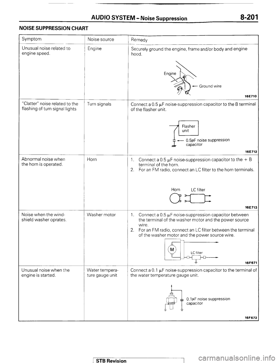
NOISE SUPPRESSION CHART
Symptom
Unusual noise related to
engine speed. ’ Remedy
Securely ground the engine, frame and/or body and engine
hood.
- Ground wire
16E71C
“Clatter” noise related to the
Turn signals
flashing of turn signal lights Connect a 0.5 FF noise-suppression capacitor to the 6 terminal
of the flasher unit.
Abnormal noise when
the horn is operated. Horn ?L - 0.5pF noise suppression
capacitor
16E71:
1. Connect a 0.5 FF noise-suppression capacitor to the + B
terminal of the horn.
2. For an FM radio, connect an LC filter to the horn terminals.
Noise when the wind-
shield washer oprates. Washer motor Horn LC filter
16E71:
1. Connect a 0.5 PF noise-suppression capacitor between
the terminal of the washer motor and the power source
wire.
2. For an FM radio, connect an LC filter between the terminal
of the washer motor and the power source wire.
Unusual noise when the
engine is started. Water tempera-
ture gauge unit Connect a 0.1 p,F noise-suppression capacitor to the terminal o
the water temperature gauge unit.
0.1 PF noise suppression
capacrtor
1 STB Revision
Page 227 of 284
BACK DOOR WINDOW DEFOGGER - Printed Heater Lines B-207
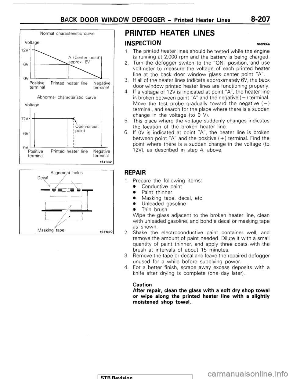
Normal characteristic curve
Voltage
I;\
Positive
terminal Printed heater line Negative
terminal
Abnormal characteristic curve
Voltage
IZV
6V
ov :-
Tf I Open-circuit
I point
I
i
!
Positive Printed heater line Negative
terminal terminal
161332
Alignme.nt holes
Masking tape
16FfiSCl
PRINTED HEATER LINES
INSPECTION N08PKAA
1. The printed heater lines should be tested while the engine
is running at 2,000 rpm and the battery is being charged.
2. Turn the defogger switch to the “ON” position, and use
voltmeter to measure the voltage of each printed heater
line at the back door window glass center point “A”.
3. If all of the heater lines indicate approximately 6V, the back
door window printed heater lines are functioning properly.
4. If a voltage of 12V is indicated at point “A”, the heater line
is broken between point “A” and the negative (-) terminal.
Move the test probe gradually toward the negative (-)
terminal, and search for the place where there is a sudden
change in the voltage (to 0 V).
5. This place where the voltage suddenly changes indicates
the location of the broken heater line.
6. If OV is indicated at point “A”, the heater line is broken
between point “A” and the positive (+) terminal. Find the
point where there is a sudden change in the voltage (to
12V). as described in step 4. above.
REPAIR
I. Prepare the following items:
e Conductive paint
@ Paint thinner
e Masking tape, decal, etc.
a, Unleaded gasoline
@ Thin brush
Wipe the glass adjacent to the broken heater line, clean
with unleaded gasoline, and bond a decal or masking tape
as shown.
2. Shake the electroconductive paint container well, and
remove the amount of paint needed. Dilute it with a small
quantity of paint thinner, and apply three coats with the
brush at intervals of about 15 minutes.
3. Remove the tape or decal and leave the repaired defogger
unused for a while before supplying power.
4. For a better finish, scrape away excess deposits with a
knife after drying is complete (one day later).
Caution
After repair, clean the glass with a soft dry shop towel
or wipe along the printed heater line with a slightly
moistened shop towel.
1 STB Revision
Page 244 of 284
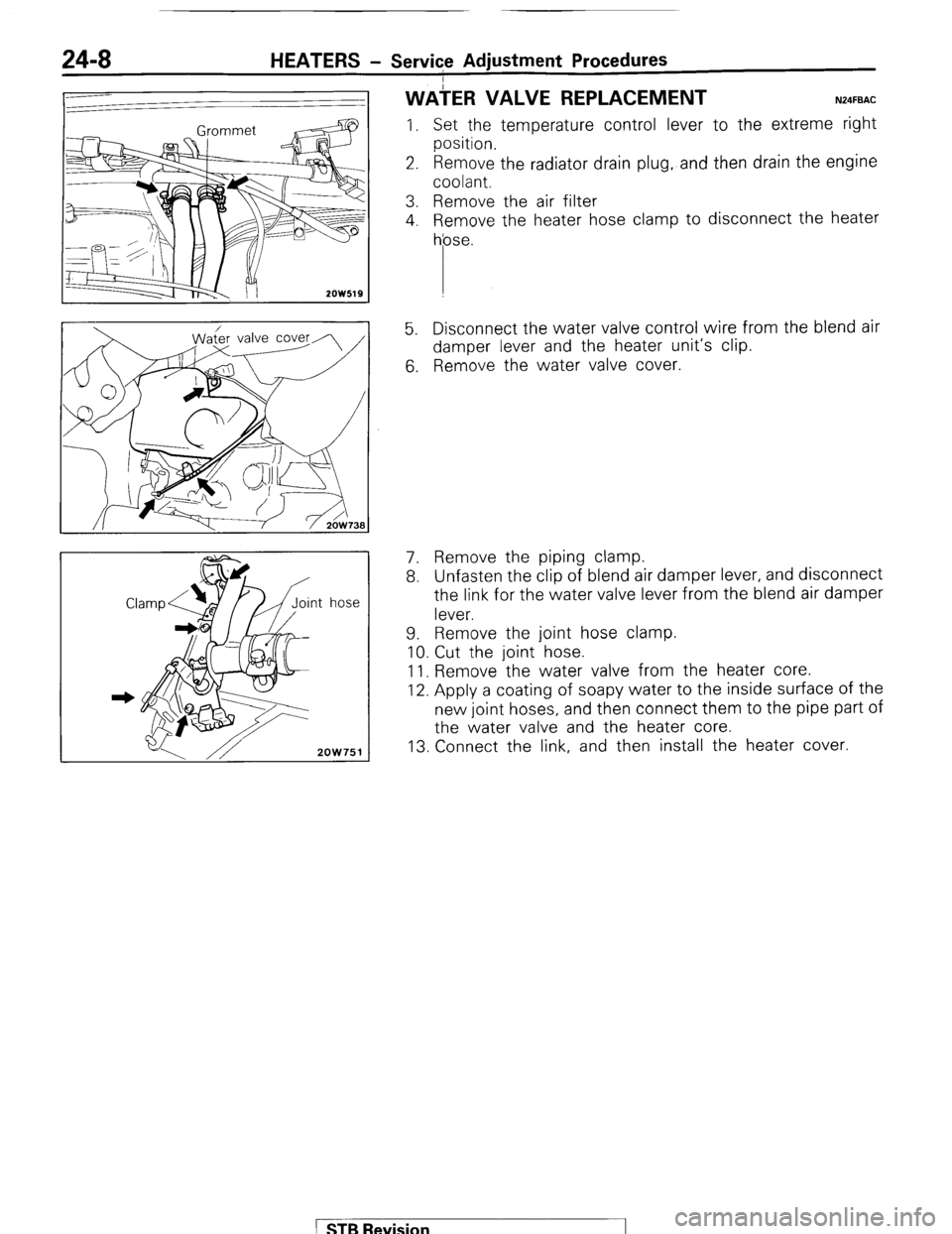
24-8 HEATERS - Service Adjustment Procedures
ater valve cover
2OW751
WAiER VALVE REPLACEMENT N24FBAC
I. Set the temperature control lever to the extreme right
position.
2. Remove the radiator drain plug, and then drain the engine
coolant.
3. Remove the air filter
4. Remove the heater hose clamp to disconnect the heater
hose.
5. Disconnect the water valve control wire from the blend air
damper lever and the heater unit’s clip.
6. Remove the water valve cover.
7. Remove the piping clamp.
8. Unfasten the clip of blend air damper lever, and disconnect
the link for the water valve lever from the blend air damper
lever.
9. Remove the joint hose clamp.
10. Cut the joint hose.
11. Remove the water valve from the heater core.
12. Apply a coating of soapy water to the inside surface of the
new joint hoses, and then connect them to the pipe part of
the water valve and the heater core.
13. Connect the link, and then install the heater cover.
1 STB Revision
Page 248 of 284
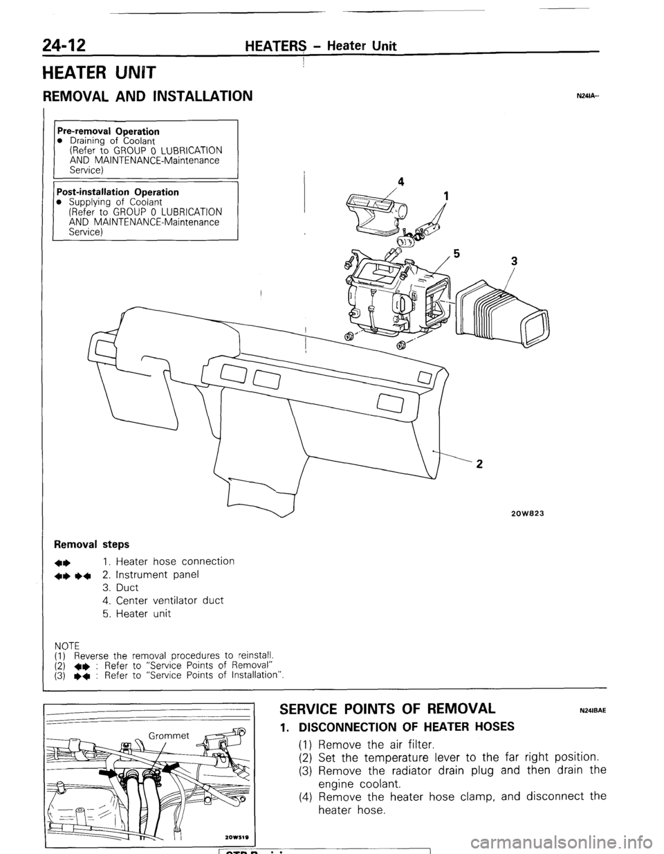
24-12 HEATERS - Heater Unit
I
HEATER UNBT
REMOVAL AND INSTALLATION
Pre-removal Operation
0 Draining of Coolant
(Refer to GROUP 0 LUBRICATION
AND MAINTENANCE-Maintenance
Service)
Post-installation Operation
0 Supplying of Coolant
(Refer to GROUP 0 LUBRICATION
AND MAINTENANCE-Maintenance
Service) Removal steps
l *
I, Heater hose connection
+* l 4
2. Instrument panel
3. Duct
4. Center ventilator duct
5. Heater unit
NOTE
(1) Reverse the removal procedures to reinstall.
(2) +e : Refer to “Service Points of Removal”
(3) l
+ : Refer to “Service Points of Installation”
2OW823
SERVICE POINTS OF REMOVAL
1. DISCONNECTION OF HEATER HOSES (1) Remove the air filter.
(2) Set the temperature lever to the far
(3) Remove the radiator drain plug and
engine coolant.
(4) Remove the heater hose clamp, and
heater hose.
N24lBAE right position.
then drain the
disconnect the
ETB Revision