fuse MITSUBISHI MONTERO 1987 1.G Owner's Guide
[x] Cancel search | Manufacturer: MITSUBISHI, Model Year: 1987, Model line: MONTERO, Model: MITSUBISHI MONTERO 1987 1.GPages: 284, PDF Size: 14.74 MB
Page 90 of 284
WIRING HARNESS - Centralized Junction
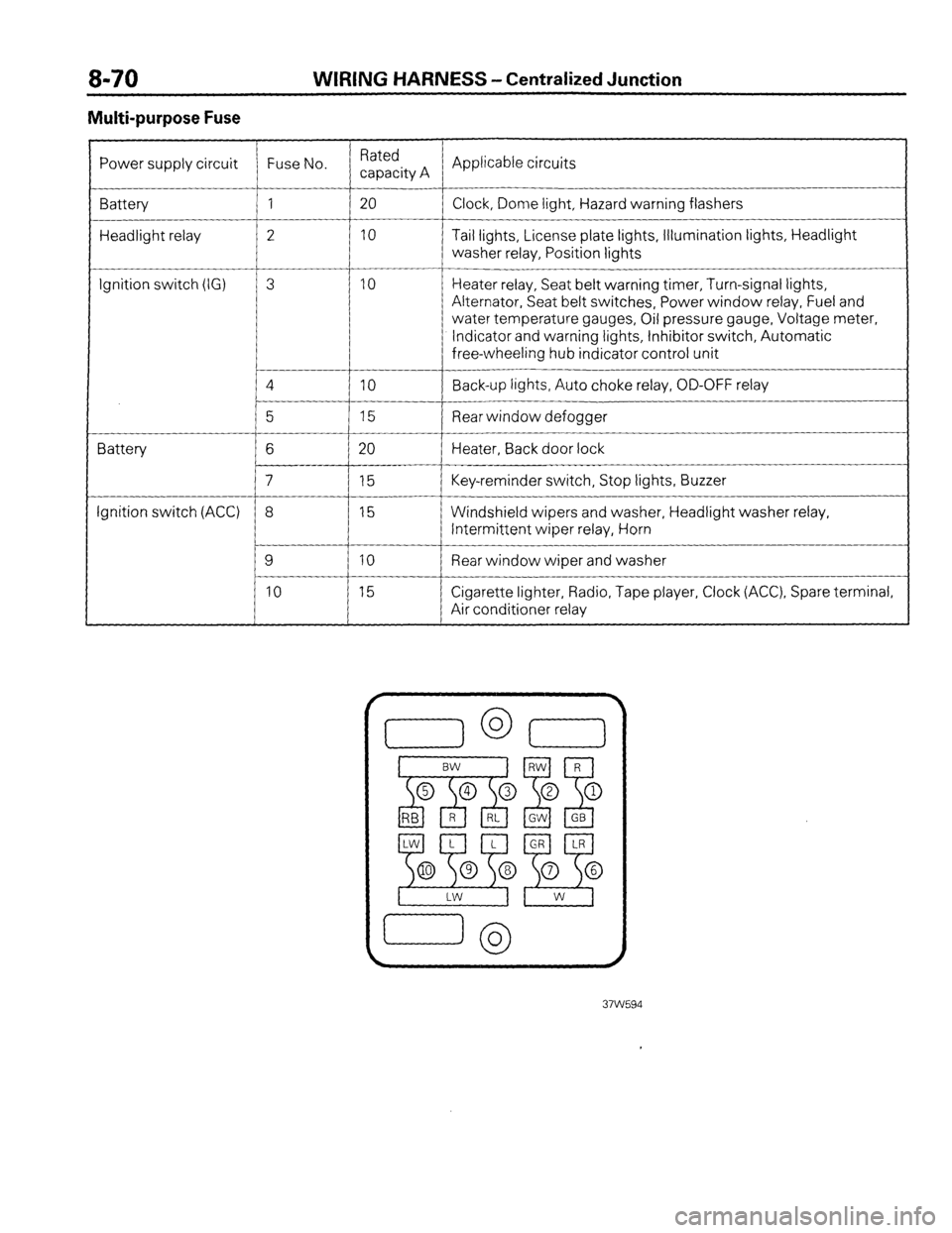
Multi-purpose Fuse
Power supply circuit Fuse No. Rated
capacity A Applicable circuits
Battery 1 20
Clock, Dome light, Hazard warning flashers
Headlight relay 2 10 Tail lights, License plate lights, Illumination lights, Headlight
washer relay, Position lights
__-
Ignition switch (IG) 3 10 Heater relay, Seat belt warning timer, Turn-signal lights,
Alternator, Seat belt switches, Power window relay, Fuel and
water temperature gauges, Oil pressure gauge, Voltage meter,
Indicator and warning lights, Inhibitor switch, Automatic
free-wheeling hub indicator control unit
4
IO Back-up lights, Auto choke relay, OD-OFF relay
__-
5 15 Rear window defogger
Battery 6 20 Heater, Back door lock
7 15 Key-reminder switch, Stop lights, Buzzer
Ignition switch (ACC) 8 15 Windshield wipers and washer, Headlight washer relay,
Intermittent wiper relay, Horn
9 10 Rear window wiper and washer
10 15 Cigarette lighter, Radio, Tape player, Clock (ACC), Spare terminal,
Air conditioner relay
Page 95 of 284
CHARGING SYSTEM -Troubleshooting 8-75
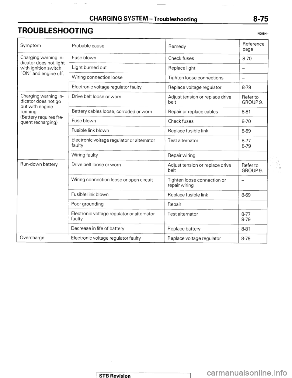
TROUBLESHOOTING
NOBEH-
Symptom Probable cause
Remedy Reference
we
Charging warning in- Fuse blown
dicator does not light
with ignition switch Light burned out
“ON” and engine off. 1
1 Wiring connection loose Check fuses
Replace light
Tighten loose connections 8-70
-
-
Charging warning in-
dicator does not go
out with engine
running
(Battery requires fre-
quent recharging)
L
t
Run-down battery
c
Electronic voltage regulator faulty
Drive belt loose or worn
Battery cables loose, corroded or worn
Fuse blown
Fusible link blown
Electronic voltage regulator or alternator
faulty
Wiring faulty
Drive belt loose or worn
Wiring connection loose or open circuit
Fusible link blown Replace voltage regulator
Adjust tension or replace drive
belt
Repair or replace cables
Check fuses
Replace fusible link
Test alternator
Repair wiring
Adjust tension or replace drive
belt
Tighten loose connection or
repair wiring
Replace fusible link 8-79
Refer to
GROUPS.
8-8 1
8-70
8-69
8-77
8-79
-
Refer to
GROUP 9.
-
8-69
Poor grounding 1 Repair
I-
I I I Electronic voltage regulator or alternator
faulty Test alternator 8-77
8-79
Overcharge Decrease in life of battery
Replace battery
8-81 I
Electronic voltage regulator faulty Replace voltage regulator 8-79
STB Revision
Page 169 of 284
LIGHTING SYSTEM - Circuit Diagram 8-149
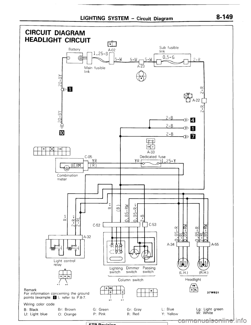
CIRCUIT DIAGRAM
HEADLIGHT CIRCUIT m
Battery
A-02 Sub fusible
link
0.5-G
5-v m5-w m 2-R
L-l
Main fusible A-23
lrnk
z
A
2-B
dl
r 2-B
I dl
ItfYH
A-33
c-05 Dedicated fuse
YR[ 11.25-Y
1-1
I
Combination
meter
I I
Wlir,L n
*
7
.-32 A
I
A-55
I
Lighting Dimmer Passing
switch switch switch
Column switch Lrght control
relay
FP R R RL
x2 XI
J
(LTH.) (R.H.)
Headlight
37W621 Remark
For information concerning the ground
points (example:
q ), refer to P.8-7.
Wiring color code
B: Black Br: Brown G: Green Gr: Gray
LI: Light blue 0: Orange P: Pink R: Red L: Blue
Y: Yellow Lg: Light green
W: White
/ STB Revision
Page 172 of 284
8-152 LIGHTING SYSTEM - Circuit Diagram
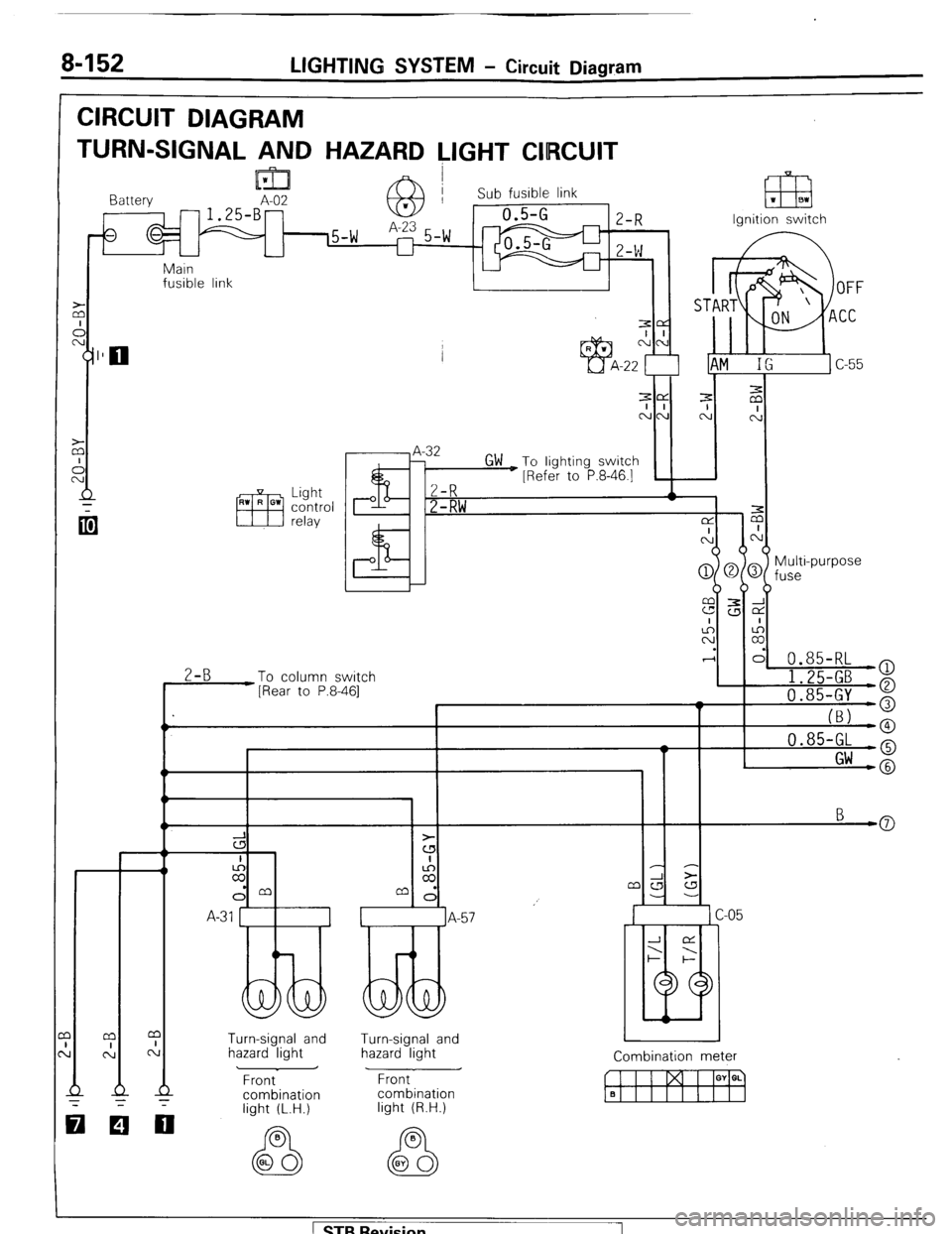
CIRCUIT DIAGRAM
TURN-SIGNAL AND HAZARD LIGHT CIIRCUIT
lml I Battery A-02 -1.25-B- 63 Sub fusible link 1 m 1 BI
Ignition switch
Main
fusible link
I 1
.I
-
z
I I I ’ I
Multi-purpose
fuse
0.85-RL
2-B
To column switch
[Rear to P.8-461 I 1.25-GB )
a
I 'I 0.85-GY o
I_
(BJ -0 0.85-GL -o
I Gw -@
3
cs
I
z
dm
A-31 1
Turn-signal and
hazard light Turn-signal and
hazard light
Front
combination Combination meter
w I I I GY a. q Front
combination
light (R.H.)
000
light (L.H.)
1 STB Revision 1
Page 175 of 284
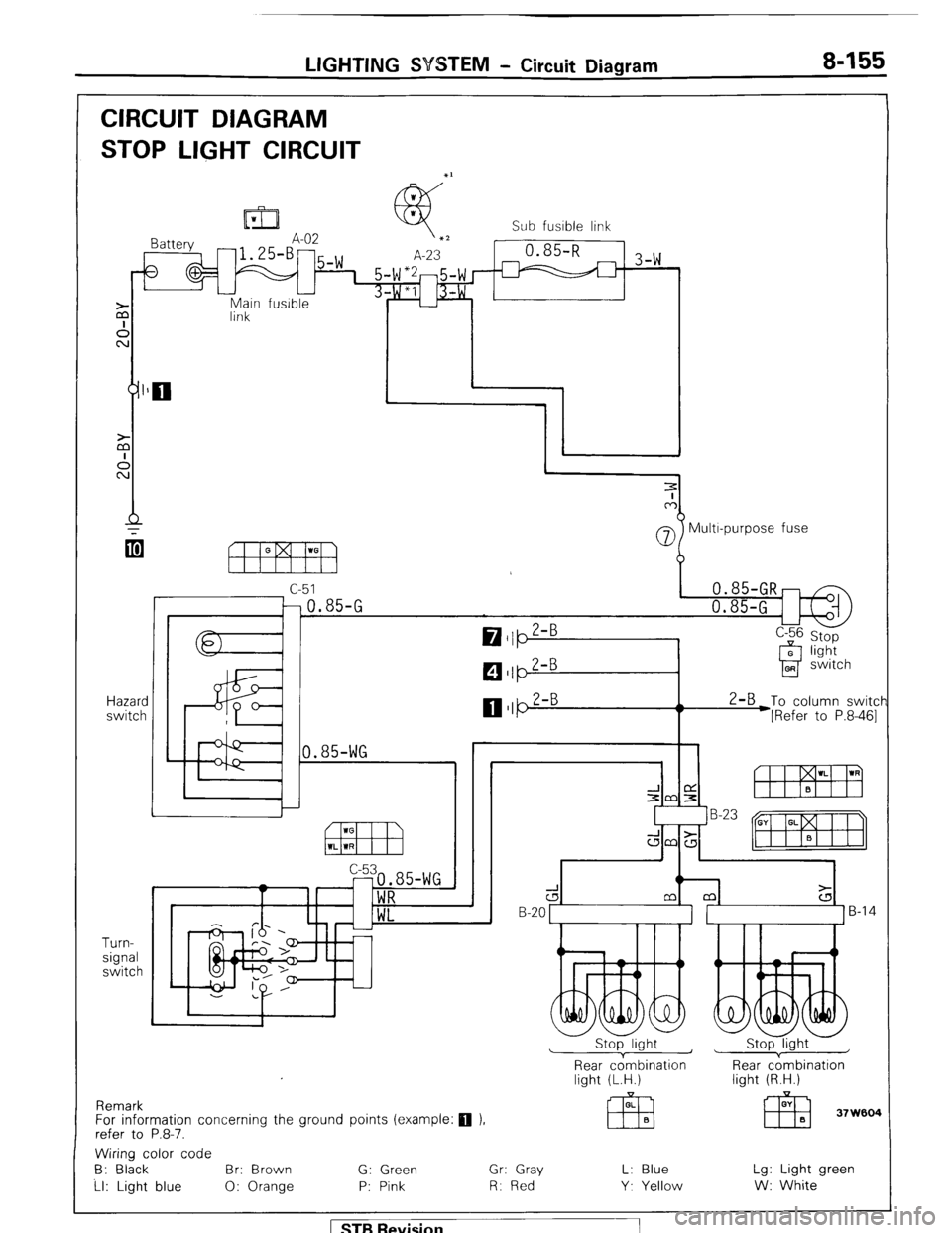
LIGHTING SYSTEM - Circuit Diagram 8-155
CIRCUIT DIAGRAM
STOP LIGHT CIRCUIT
Main fusible
link
Hazard
switch
Turn-
signal
switch Sub fusible link
-1 3-w
07 Multr-purpose fuse
c-51
-0.85-G
0.85-WG 2-B
To column switcf
*[Refer to P.8-461
Remark
For information concerning the ground points (example:
q ).
refer to P.8-7.
d B-20 1 ]B-14
Stop light ~
1 Stop light
Rear cdmbination
light (L.H.) Rear c;mbination
light (R.H.)
Wiring color code
B: Black Br: Brown G: Green Gr: Gray L: Blue Lg: Light green
Ll: Light blue 0: Orange P: Pink R: Red Y. Yellow W: White
1 STB Revision
Page 176 of 284
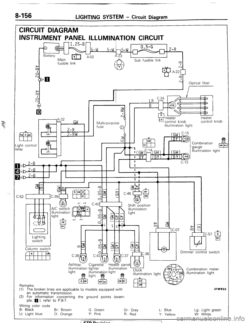
8-156 LIGHTING SYSTEM - Circuit Diagram
CIRCUIT DIAGRAM
INSTRUMENT PANEL ILLUMINATION CORCUIT
-1.25-B-
0
.5-w 0.5-G
2-R
Battery
-Err
5-w 15-w r
Main ’ A-02 A-23
Sub fusible link
fusible link a
I
z N
A A-22 [
cy]llo CY
c-i
Optical fiber
I
Multi-purpose
fuse Heater
control knob
illumination light Heater
control knob
ght control
lay Combination
gauge B 01 0’
Illumination light
/ n
c
C
-
c-57 0 ti
Q BY Lighting
switch
Dimmer control switch
rel
Combination meter
illumination light illumination lighter
Remarks
(1) The broken lines are applicable to models eouipped with
37W822 an automatic transmission.
(2) For information concerning the ground points (exam-
ple: 0 1, refer to P.8-7.
Wiring color code
6: Black
Br: Brown G: Green
Ll: Light blue Gr: Gray
0: Orange P: Pink
R: Red L: Blue
Y: Yellow Lg: Light green
W: White 1 ST6 Revision
Page 188 of 284
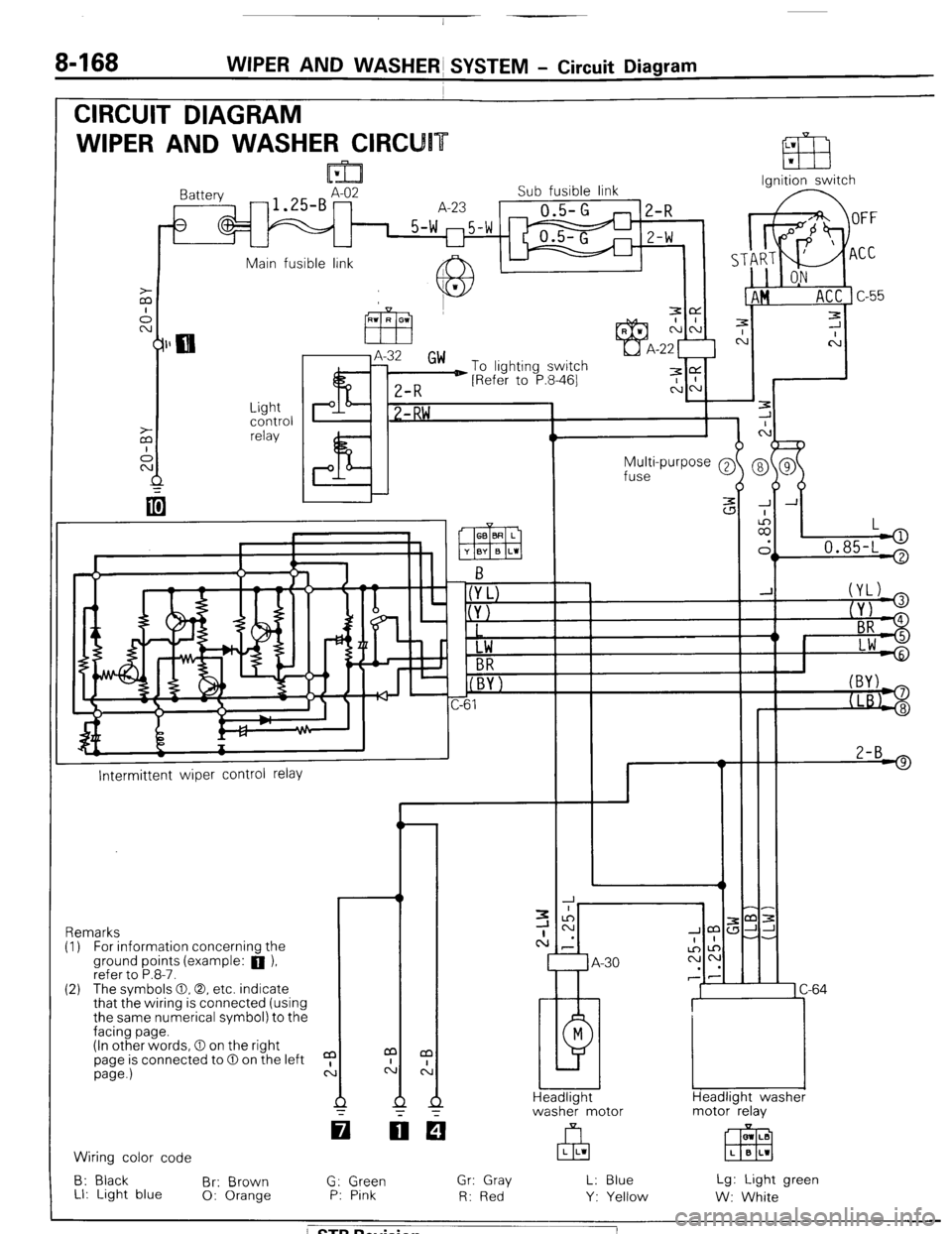
8468 WIPER AND WASHERS SYSTEM - Circuit Diagram
CIRCUIT DIAGRAM
WIPER AND WASHER CIRCU
Ignition switch
lattery
-1.SBAz2 Sub fusible link
A-23
0.5-G
1 5-w m5-w
U
2-R
Z-W
Main fusible link A IL
J.
c
7
C
-
-
-
-
-
-
J A
:
II,
L
.
> 0.85-L '
Light
control
relay P I? 1 -RW ,
Multi-purpose @
fuse
2-B 9
I--
Intermittent wiper control relay
-r ,m:
JJ-
-.
1 C-64
Headlight washer
motor relay Remarks
(I) For information concernina the
ground points (example: a ),
refer to P.8-7.
(2) The svmbols 0.0. etc. indicate
that the wiring is connected (using
the same numerical symbol) to the
facing page.
(In other words, 0 on the right
page is connected to 0 on the left
page.)
a
c: m LB
EEEI L B L1 Wiring color code
B: Black
Br: Brown
LI: Light blue 0: Orange G: Green
P: Pink Gr: Gray
R: Red L: Blue
Y: Yellow Lg: Light green
W: White
/ STB Revision
Page 205 of 284
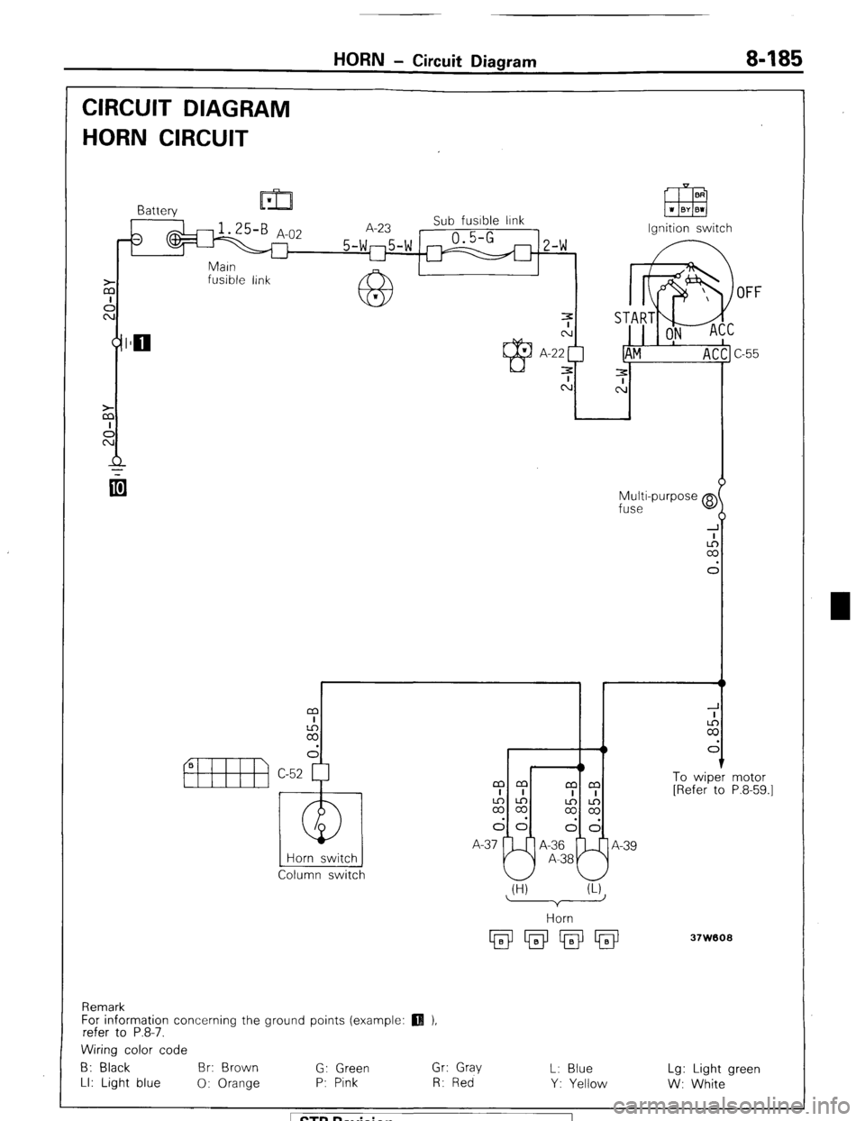
HORN - Circuit Diagram 8485
CIRCUIT DIAGRAM
HORN CIRCUIT
fusible link
OFF
Multi-purpose @
fuse
I r t
m
I
2
d
1 To wiper
[Refer to
Horn switch
Column switch mm
mm
I I
I I
2%
$2
dd
I--J!
dd
A-37 A-36
A-39
A-38 motor
P.8-59.1
(H) (U
37W608
Remark
For information concerning the ground points (example:
refer to P.8-7.
Wiring color code
B: Black Br: Brown
G: Green Gr: Gray
L: Blue Lg: Light green
LI: Light blue
0: Orange P: Pink R: Red
Y: Yellow
W: White 1 STB Revision
Page 209 of 284
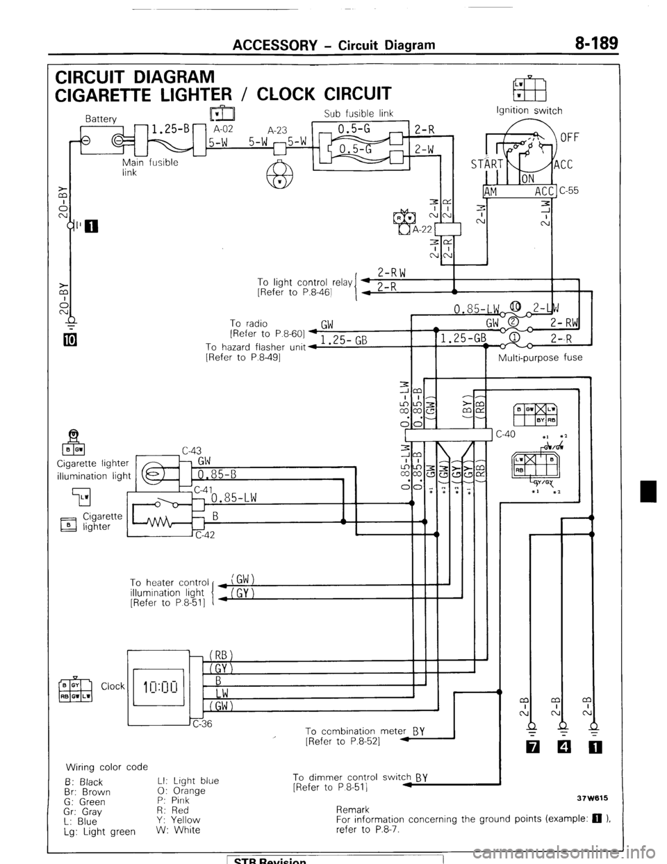
ACCESSORY - Circuit Diagram 8-189
CIRCUIT DIAGRAM
LW
CIGARETTE LIGHTER / CLOCK CIRCUIT EB w
Sub fusible link
,-fs q M 15-W 5-W 25-W m ;I;
I I
-
Main fusible -
link Ignition switch
3e
I I
NN
,
Z-RW To
linht cnntrnl r&v I 4 0 n
I 1 - .J . __._ - -., [Refer to P.8-461
I 4 L-K A
To radio
GW [Refer to P.8-601 + 1 .25- GB
To hazard flasher unit4
[Refer to P.8-491
Multi-purpose fuse
illumination light
’ To heater control
illumination light
[Refer to P 8-511
r
i I
To combination meter BY
Wiring color code
B: Black LI: Light blue
Br: Brown 0: Orange
G: Green P: Pink
Gr: Gray R: Red
L: Blue Y: Yellow
Lg: Light green W: White
I
I - - m
I
N
Q
-
[Refer to P.8-521 -
To dimmer control switch BY
[Refer to P 8-511 .I
Remark 37W615
For information concerning the ground points (example: 0 ).
refer to P.8-7.
1 STB Revision
Page 225 of 284
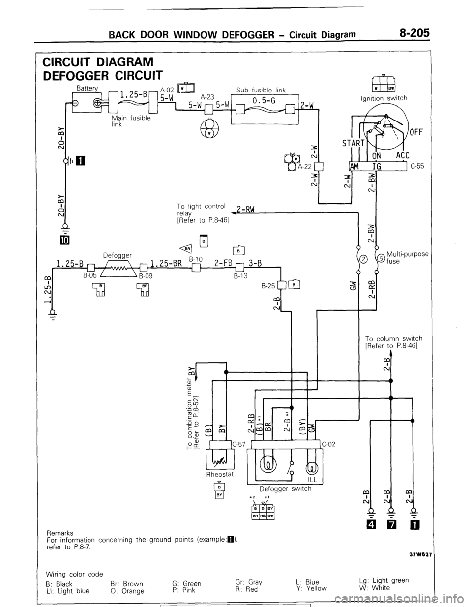
BACK DOOR WINDOW DEFOGGER - Circuit Diagram 8-205
CIRCUIT DUAGRAM
DEFOGGER CIRCUIT -t IDI L
m
- H-UL Ll&J Sub fusible link
5-w A-23 0.5-G 1 5-w"5'w m
z-w ,
u
fusible ignition switch
Main
link
To light control
relay w zmR~
[Refer to P.8-461
q--l-
2 @fuse
i
Multi-purpose m
E
c:
t
To column switch
[Refer to P.8-461
1.25-B
a
c!
Rheostat
Defogger switch a
cl
31 W02:
Remarks
For information concerning the ground points (example:D).
refer to P.8-7.
Wiring color code
B: Black Br: Brown G: Green Gr: Gray L: Blue Lg: Light green
LI: Light blue 0: Orange P: Pink R: Red Y: Yellow W: White STB Revision