ignition MITSUBISHI MONTERO 1987 1.G Manual Online
[x] Cancel search | Manufacturer: MITSUBISHI, Model Year: 1987, Model line: MONTERO, Model: MITSUBISHI MONTERO 1987 1.GPages: 284, PDF Size: 14.74 MB
Page 234 of 284
8-214 AUTOM TIC FREE-WHEELING VU6 INDICATOR SYSTEM - Circuit Diagram
I
m I IA-21 m
v?~
r:
BI I To column switch
2
[Refer to P.8-461 CT
= 9’i A I
I
m z
I ’
c: d
I ’
LR
!J
I I 1
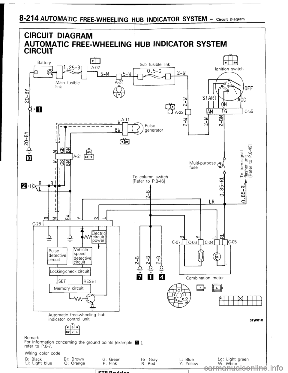
CIRCUIT DIAGRAM
AUTOMATIC FREE-WHEELING HUB INDICATOR SYSTEM
CIRCUIT
F==e=%
Battery lu-!
A-02 Sub fusible link
- 15-w r-)5-w 0.5-G
2-w
I I I I
Main fusible
link
7
N
-22
3
Pulse c:
generator
h Ignition switch
I /Locking check circuit 1
q IIEI Combination meter
Automatic free-wheeling hub
indicator control unit
1 B R
Em El1 Y L
Remark
For information concerning the ground points (example: q ),
refer to P.8-7.
37W610
Wiring color code
B: Black Br: Brown
G: Green L: Blue
LI: Light blue Lg: Light green
0: Orange P: Pink “,r: RG,‘d”Y
Y: Yellow
W: White
1 STB Revision
Page 236 of 284
8-216 AUTOMATIC FREE-WHEELING HUB INDICATOR SYSTEM - Control Unit
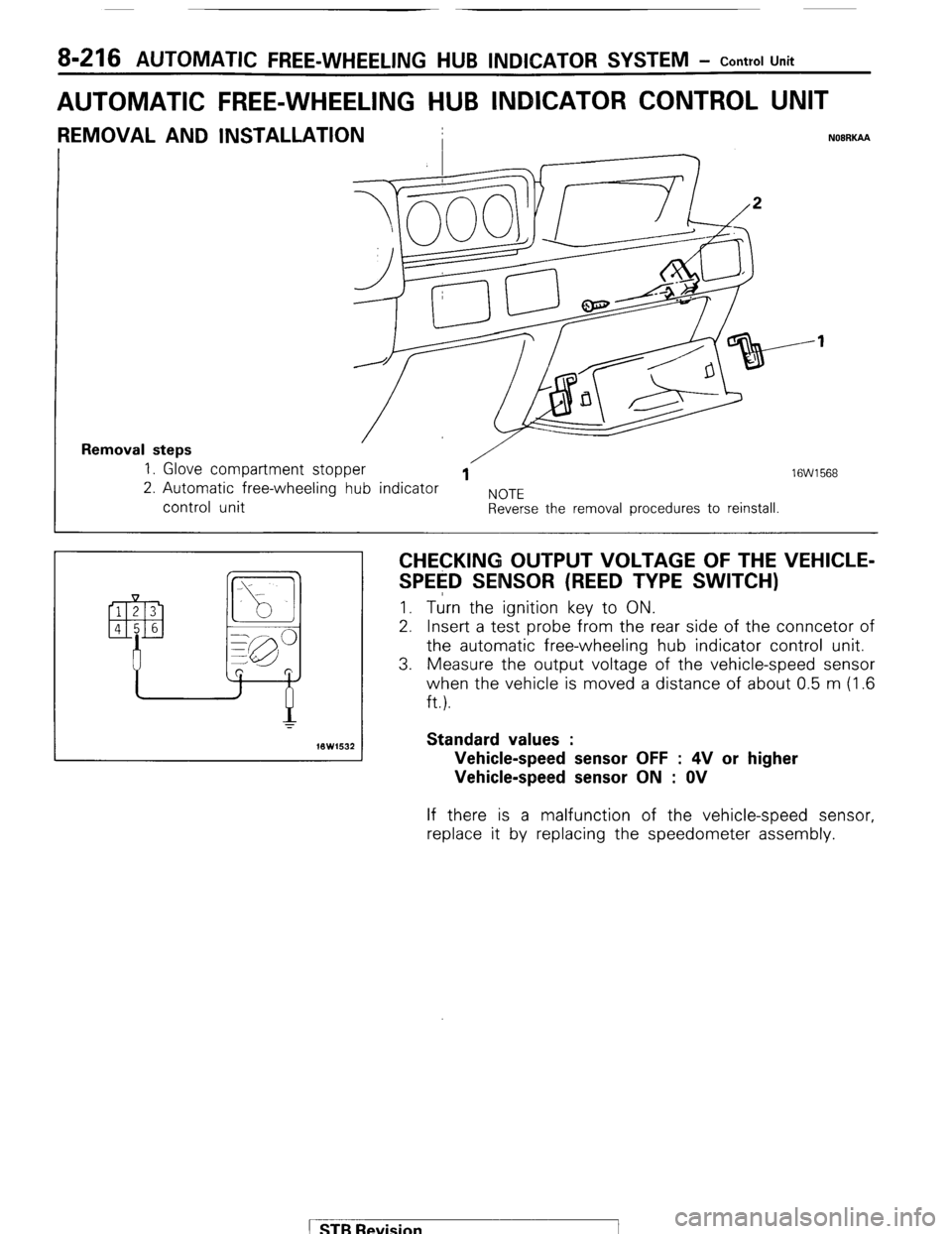
AUTOMATIC FREE-WHEELING HUB INDICATOR CONTROL UNIT
REMOVAL AND INSTALLATION
I NOBRKAA
Removal steps 1. Glove compartment stopper /
1 16W1568 2. Automatic free-wheeling hub indicator
NOTE control unit Reverse the removal procedures to reinstall.
CHECKING OUTPUT VOLTAGE OF THE VEHICLE-
SPE$D SENSOR (REED TYPE SWITCH) I. Turn the ignition key to ON.
2. Insert a test probe from the rear side of the conncetor of
the automatic free-wheeling hub indicator control unit.
3. Measure the output voltage of the vehicle-speed sensor
when the vehicle is moved a distance of about 0.5 m (1.6
ft.).
Standard values :
Vehicle-speed sensor OFF : 4V or higher
Vehicle-speed sensor ON : OV If there is a malfunction of the vehicle-speed sensor,
replace it by replacing the speedometer assembly.
( STB Revision
Page 240 of 284
24-4 HEATERS c Circuit Diagram
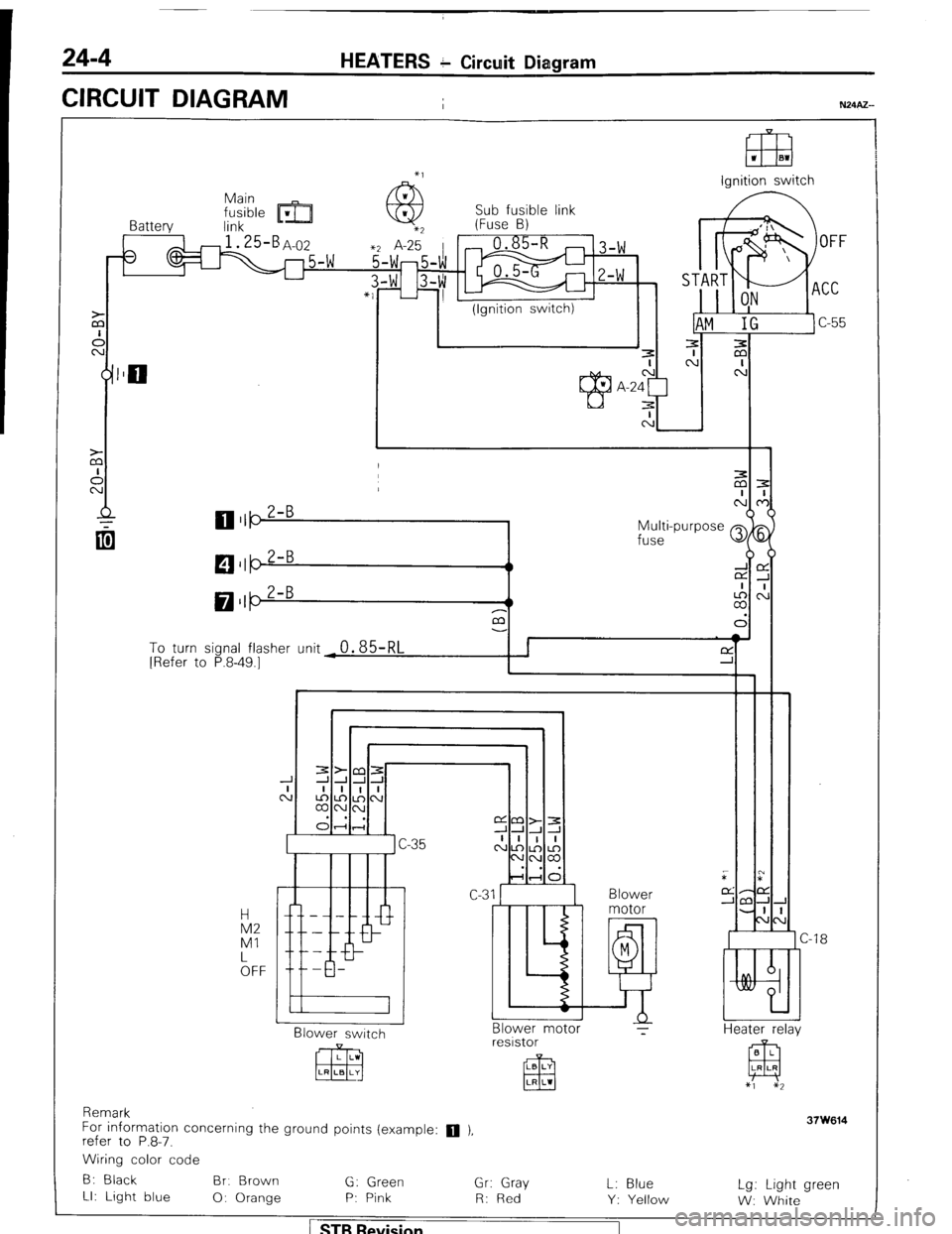
CIRCUIT DIAGRAM
I
El3 1 El1
lanition switch
Sub fusible link
Battery link m- (Fuse B)
3
1 I (Ignition switch)
Multi-purpose Q
fuse
M $5
LA,:
a3
To turn sional flasher (Init
0.85RI I I f-Y ’ I [Refer to P.8-49.7- - - ‘d -r i
I Blower
Blower switch
CJ -18
Heater r&v Blower motor ?
resistor
Remark
For information concerning the ground points (example:
q ),
refer to P.8-7.
Wiring color code
B: Black Br. Brown
G: Green
Gr: Gray
LI: Light blue
0: Orange P: Pink
R: Red L: Blue
Y: Yellow Lg: Light green
W: White
1 STB Revision
Page 262 of 284
24-26 AIR-CONDITIONING - Circuit Diagram
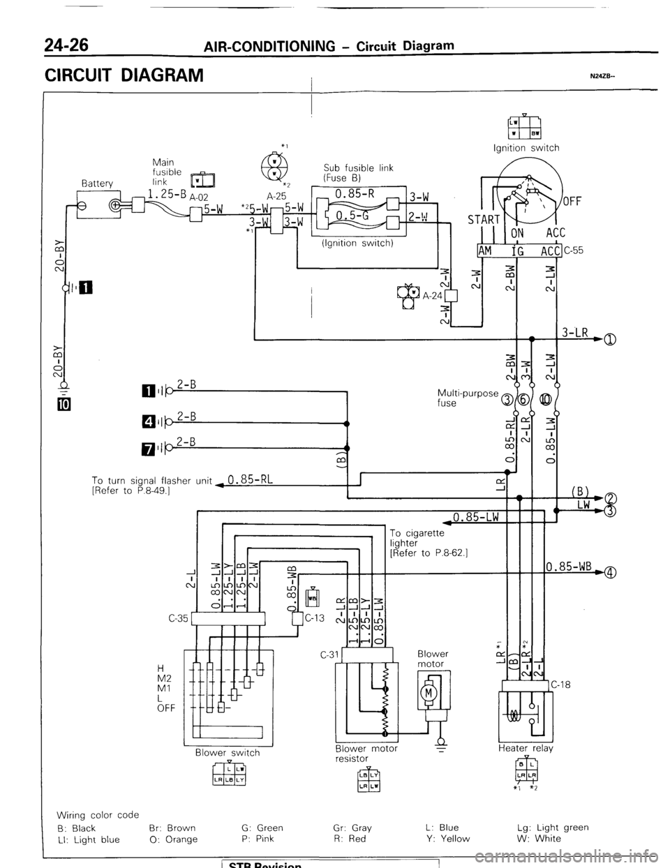
CIRCUIT DIAGRAM I N24ZB--
Ignition switch
Main
link Sub fusible link
(Fuse B)
I Battery
3
To turn signal flasher unit ~
0.85-RL [Refer to P.8-49.1
i
I 1 ,0.85-LW F
0.85-WB*
“yl lLG1 [Refer to P.8-62.1
C-C
Blower
motor
M
E!! Blower motor
T IA2
Ml
kFF -18
Heater relav N BI ower switch B L
EEJ LR LR resistor
LB LY
El3 LR LI
x’, $2
Wiring color code
B: Black Br: Brown G: Green
Gr: Gray L: Blue Lg: Light green
LI: Light blue 0: Orange P: Pink R: Red
Y: Yellow W: White
/ ST6 Revision
Page 266 of 284
24-30 AIR-CONDITIONING -Service Adjustunent Procedures
(4) If the sight glass shows foam or bubbles, the systpm could be low on charge. Occasional foam or bubbles are
normal when the ambient temperature is above 43”C(110”F) or below 21”C(7O”F).
Adjust the engine speed to 1,500 rpm. Block the airflow through the condenser to increase the compressor
discharge pressure to 1,422 to 1,520 kPa (20$ to 220 dsi). If sight glass still shows bubbles or foam, system charge
level is low.
The refrigerant system will not be low on charge unless there is a leak. Find and repair the leak. If the leak can be
repaired without discharging the system an oil level check is not necessary. Use the procedure for correcting low
refrigerant level found in the Refrigerant Sy$em Service Procedure Section.
FUSIBLE PLUG
When ambient temperature of the fusible plug reach& 105~221~F), the fusible plug melts and the refrigerant in
the system is released.
Once the fusible plug is operated, it cannot be used again.
SO, it is necessary to install new one and charge the refrigerant in the system.
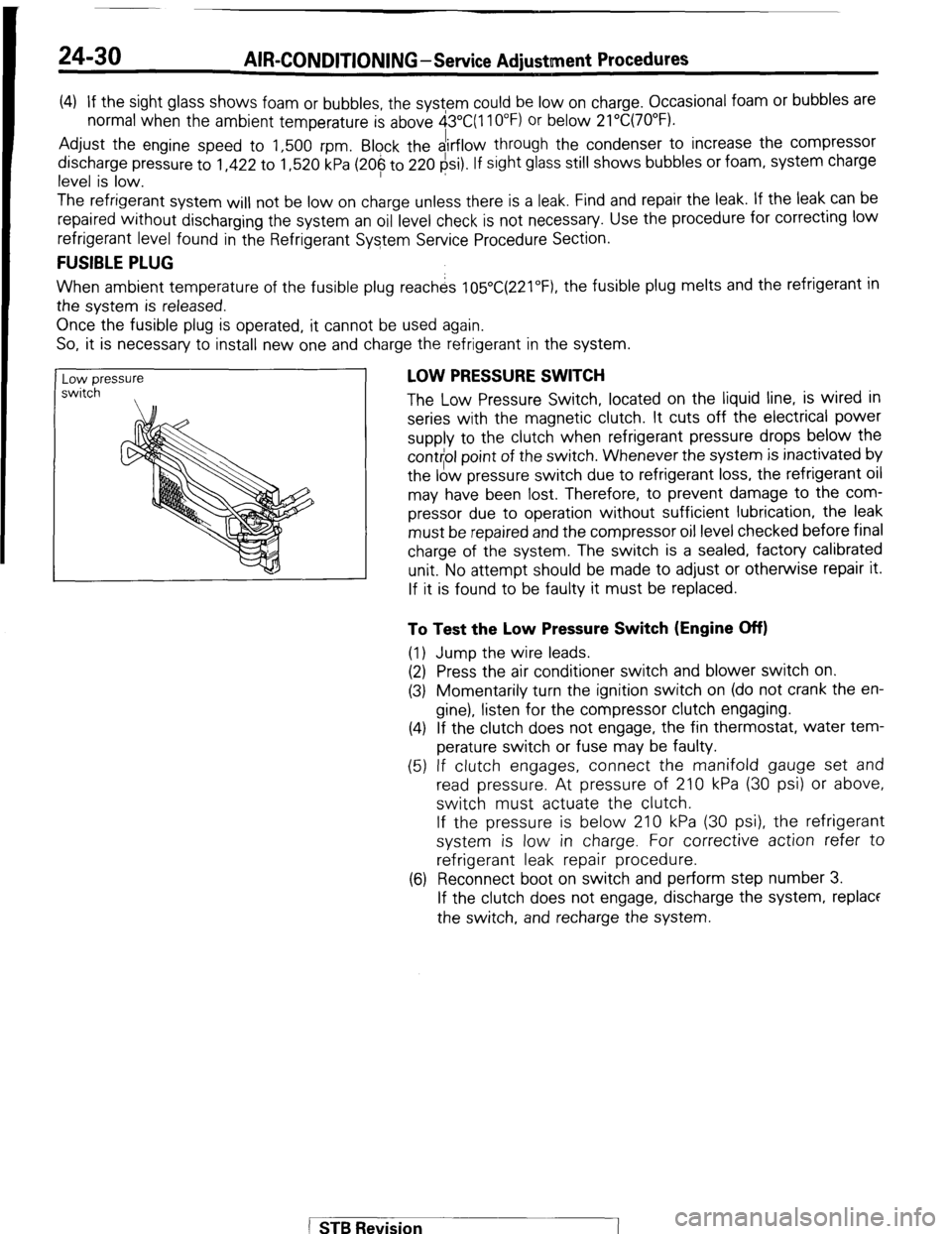
Low pressure
switch , LOW PRESSURE SWITCH
The Low Pressure Switch, located on the liquid line, is wired in
series with the magnetic clutch. It cuts off the electrical power
supply to the clutch when refrigerant pressure drops below the
cont$ol point of the switch. Whenever the system is inactivated by
the low pressure switch due to refrigerant loss, the refrigerant oil
may have been lost. Therefore, to prevent damage to the com-
pressor due to operation without sufficient lubrication, the leak
must be repaired and the compressor oil level checked before final
charge of the system. The switch is a sealed, factory calibrated
unit. No attempt should be made to adjust or otherwise repair it.
If it is found to be faulty it must be replaced.
To Test the Low Pressure Switch (Engine Off)
(1) Jump the wire leads.
(2) Press the air conditioner switch and blower switch on.
(3) Momentarily turn the ignition switch on (do not crank the en-
gine), listen for the compressor clutch engaging.
(4) If the clutch does not engage, the fin thermostat, water tem-
perature switch or fuse may be faulty.
(5) If clutch engages, connect the manifold gauge set and
read pressure. At pressure of 210 kPa (30 psi) or above,
switch must actuate the clutch.
If the pressure is below 210 kPa (30 psi), the refrigerant
system is low in charge. For corrective action refer to
refrigerant leak repair procedure.
(6) Reconnect boot on switch and perform step number 3.
If the clutch does not engage, discharge the system, replace
the switch, and recharge the system.
[
STB Revision
Page 267 of 284
AIR-CONDITIONING-Service Adiustment Procedures 24-31
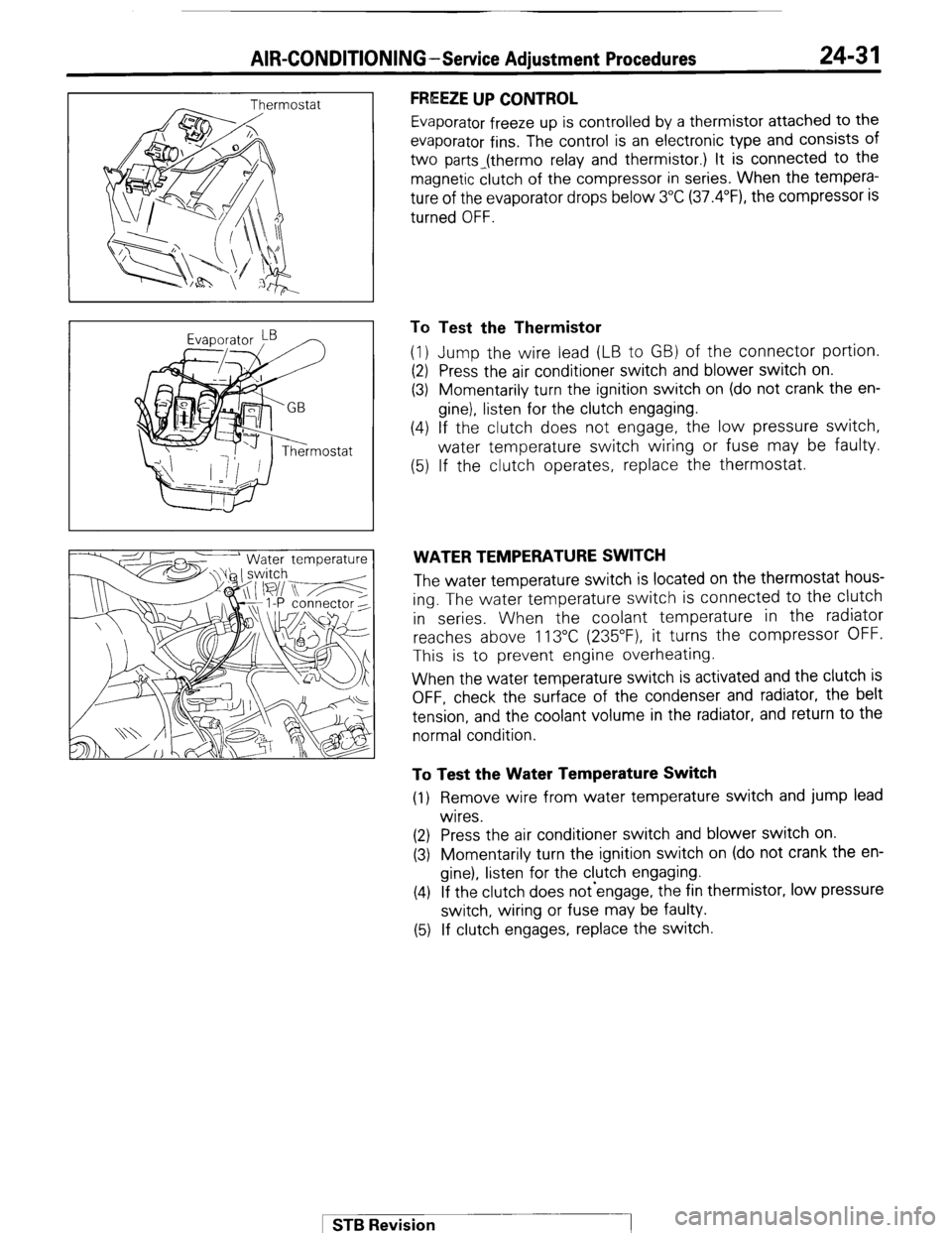
FREEZE UP CONTROL
Evaporator freeze up is controlled by a thermistor attached to the
evaporator fins. The control is an electronic type and consists of
two parts_(thermo relay and thermistor.) It is connected to the
magnetic clutch of the compressor in series. When the tempera-
ture of the evaporator drops below 3°C (37.4”F), the compressor is
turned OFF.
To Test the Thermistor
(1) Jump the wire lead (LB to GB) of the connector portion.
(2) Press the air conditioner switch and blower switch on.
(3) Momentarily turn the ignition switch on (do not crank the en-
gine), listen for the clutch engaging.
(4) If the clutch does not engage, the low pressure switch,
water temperature switch wiring or fuse may be faulty.
(5) If the clutch operates, replace the thermostat.
WATER TEMPERATURE SWITCH
The water temperature switch is located on the thermostat hous-
ing. The water temperature switch is connected to the clutch
in series. When the coolant temperature in the radiator
reaches above 113°C (235”F), it turns the compressor OFF.
This is to prevent engine overheating.
When the water temperature switch is activated and the clutch is
OFF, check the surface of the condenser and radiator, the belt
tension, and the coolant volume in the radiator, and return to the
normal condition.
To Test the Water Temperature Switch
(1) Remove wire from water temperature switch and jump lead
wires.
(2) Press the air conditioner switch and blower switch on.
(3) Momentarily turn the ignition switch on (do not crank the en-
gine), listen for the clutch engaging.
(4) If the clutch does not-engage, the fin thermistor, low pressure
switch, wiring or fuse may be faulty.
(5) If clutch engages, replace the switch.
1 STB Revision
Page 268 of 284
24-32 AIR-CONDITIONING-Service Adjustment Procedures
i--
9 >
@
r
2ouo319
- 2OW627 I
Suction gauge Discharge w-w
/ I
Suction
ww Discharge
w-w
2OUO306
Suction
w-w Discharge
gauge
2OUO307
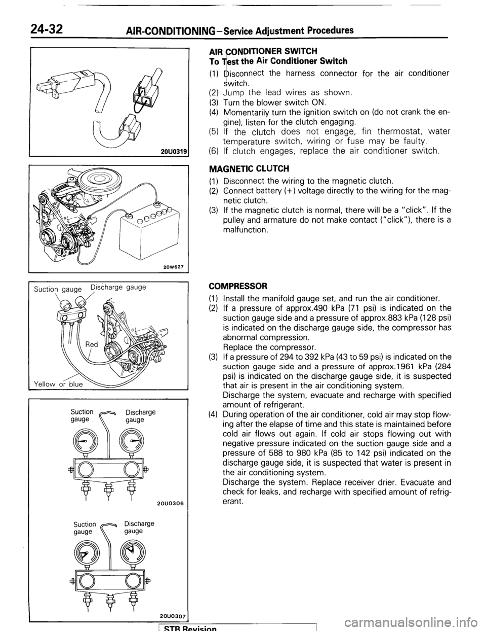
AIR CONDITIONER SWITCH
To jest the Air Conditioner Switch
(1) Disconnect the harness connector for the air conditioner
switch.
(2) Jump the lead wires as shown.
(3) Turn the blower switch ON.
(4) Momentarily turn the ignition switch on (do not crank the en-
gine), listen for the clutch engaging.
(5) If the clutch does not engage, fin thermostat, water
temperature switch, wiring or fuse may be faulty.
(6) If clutch engages, replace the air conditioner switch.
MAGNETIC CLUTCH
(1) Disconnect the wiring to the magnetic clutch.
(2) Connect battery (+) voltage directly to the wiring for the mag-
netic clutch.
(3) If the magnetic clutch is normal, there will be a “click”. If the
pulley and armature do not make contact (“click”), there is a
malfunction.
COMPRESSOR
(1) Install the manifold gauge set, and run the air conditioner.
(2) If a pressure of approx.490 kPa (71 psi) is indicated on the
suction gauge side and a pressure of approx.883 kPa (128 psi)
is indicated on the discharge gauge side, the compressor has
abnormal compression.
Replace the compressor.
(3) If a pressure of 294 to 392 kPa (43 to 59 psi) is indicated on the
suction gauge side and a pressure of approx.1961 kPa (284
psi) is indicated on the discharge gauge side, it is suspected
that air is present in the air conditioning system.
Discharge the system, evacuate and recharge with specified
amount of refrigerant.
(4) During operation of the air conditioner, cold air may stop flow-
ing after the elapse of time and this state is maintained before
cold air flows out again. If cold air stops flowing out with
negative pressure indicated on the suction gauge side and a
pressure of 588 to 980 kPa (85 to 142 psi) indicated on the
discharge gauge side, it is suspected that water is present in
the air conditioning system.
Discharge the system. Replace receiver drier. Evacuate and
check for leaks, and recharge with specified amount of refrig-
erant.
/ STB Revision