Buzzer MITSUBISHI MONTERO 1987 1.G Workshop Manual
[x] Cancel search | Manufacturer: MITSUBISHI, Model Year: 1987, Model line: MONTERO, Model: MITSUBISHI MONTERO 1987 1.GPages: 284, PDF Size: 14.74 MB
Page 52 of 284
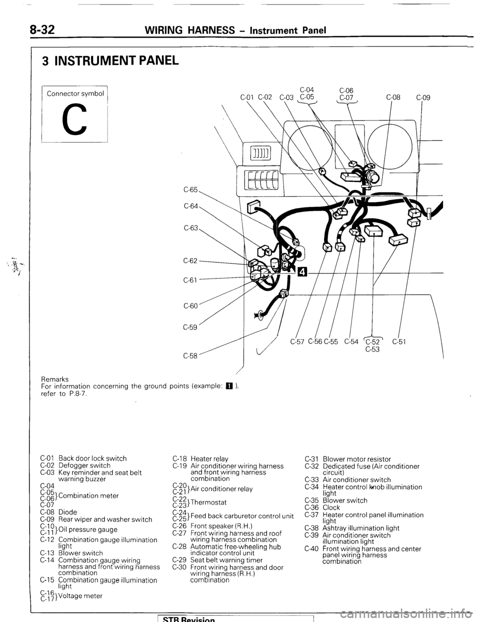
8-32 WIRING HARNESS - Instrument Panel
3 INSTRUMENT PANEL
Connector symbol
C
C-65 c-04
C-06
C-64
C-63
C-61
CL57 C-b6 C!55 d54 c!5
Remarks
For information concerning the ground points (example:
q ),
refer to P.8-7.
C-01 Back door lock switch
C-02 Defogger switch
C-03 Kev reminder and seat belt
warning buzzer
c-04
pi;’ Combination meter
C-08 Diode
C-09 Rear wiper and washer switch
r&~}Oil pressure gauge
C-12 f;hybination gauge illumination
C-l 3 Blower switch
C-14 Combination gauge wiring
harness and front wiring harness
combination
C-15 F;hybination gauge illumination
C,::F}Voltage meter C-l 8 Heater relay
C-l 9 Air conditioner wiring harness
and front wiring harness
combination
E:$)}Air conditioner relay C-31 Blower motor resistor
C-32 Dedicated fuse (Air conditioner
circuit)
C-33 Air conditioner switch
C-34 yl;Jer control lonob illumination
$:;;I Thermostat
$:;;I Feed back carburetor control unit
C-26 Front speaker (R.H.)
C-27 Front wiring harness and roof
wiring harness combination
C-28 Automatic free-wheeling hub
indicator control unit
C-29 Seat belt warning timer
C-30 Front wiring harness and door
wiring harness (R.H.)
combination c-35
C-36
c-37
C-38
c-39
c40
“3’ ‘. Blower switch
Clock
Heater control panel illumination
light
Ashtray illumination light
Air conditioner switch
illumination light
Front wiring harness and center
panel wiring harness
combination
[ STB Revision
Page 72 of 284
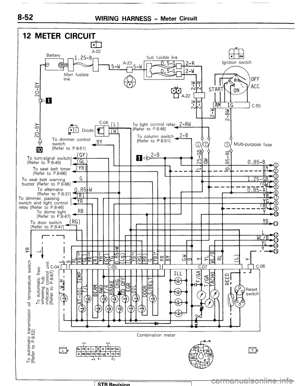
WIRING HARNESS - Meter Circuit
12 METER CIRCUIT
m 1 A-02
Sub fusible link
15-w Ignition switch
Main fusible -
--
link
A-22
‘1
m -ffiFirmer control BY
4
[Refer to P.8-511
I I 0 column :
[Refer to P.E
@/ Multi-purpose fuse
(bYI
To turn,signal switchfd,,, ,
[Refer to P.8-491 1
To seat belt timer
[Refer to P.8-661
To seat belt warning
buzzer [Refer to P.8-661 M
G 1
I
To alternator
fRefer to P.8-371
0.85tW
41D 1 I 4
‘o dimmer, passir-
witc , “,, ,
:h and light control Ir r n ! , I I I
clay [Refer to P.8461 ~ -_
To dome light Kb
[Refer to P.8-471 4
To door yi~“,h,,_(RG)
ID,.&-* +,.
1
I YBdD t
m ”
q
3
-ly-J
_-- -_ I- r
Combination meter
1 STB Revision
Page 86 of 284
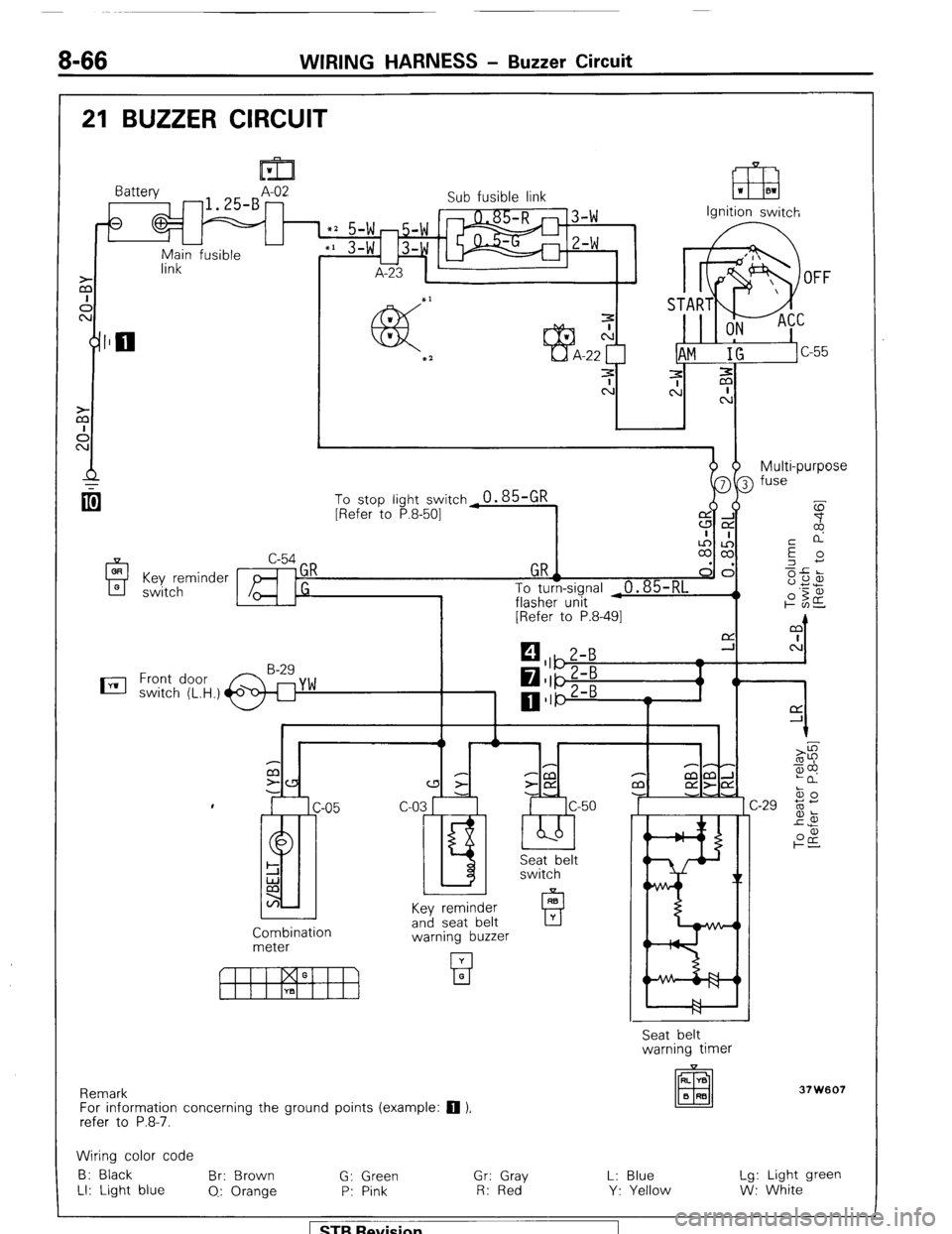
8-66 WIRING HARNESS - Buzzer Circuit
21 BUZZER CIRCUIT
OR
A 0 Key reminder
switch
nil 1
link Battery A-02
-1.25-B -
0
-
Main fusible Sub fusible link
IT8 ‘I 01
Ignition switch
dhm b- Multi-purpose
[Refer to P.8-491
0 1
C P-P
a 3
-CCl P mm-l
z- z-CY m aa-cd
c-03 r c-50 -J -.A
I.5 ‘bb’ IC ski&t
switch
Key reminder
Combination
meter and seat belt
warning buzzer
Remark
For information concerning the ground points (example:
q ),
refer to P.8-7. Seat belt
warning timer
37W607
Wiring color code
B: Black Br: Brown
G: Green Gr: Gray L: Blue Lg: Light green
LI: Light blue
0.: Orange P: Pink R: Red Y: Yellow W: White 1 ST9 Revision
Page 90 of 284
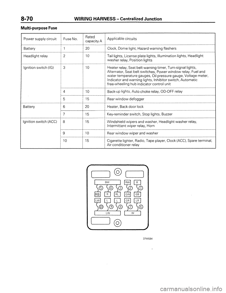
WIRING HARNESS - Centralized Junction
Multi-purpose Fuse
Power supply circuit Fuse No. Rated
capacity A Applicable circuits
Battery 1 20
Clock, Dome light, Hazard warning flashers
Headlight relay 2 10 Tail lights, License plate lights, Illumination lights, Headlight
washer relay, Position lights
__-
Ignition switch (IG) 3 10 Heater relay, Seat belt warning timer, Turn-signal lights,
Alternator, Seat belt switches, Power window relay, Fuel and
water temperature gauges, Oil pressure gauge, Voltage meter,
Indicator and warning lights, Inhibitor switch, Automatic
free-wheeling hub indicator control unit
4
IO Back-up lights, Auto choke relay, OD-OFF relay
__-
5 15 Rear window defogger
Battery 6 20 Heater, Back door lock
7 15 Key-reminder switch, Stop lights, Buzzer
Ignition switch (ACC) 8 15 Windshield wipers and washer, Headlight washer relay,
Intermittent wiper relay, Horn
9 10 Rear window wiper and washer
10 15 Cigarette lighter, Radio, Tape player, Clock (ACC), Spare terminal,
Air conditioner relay
Page 144 of 284
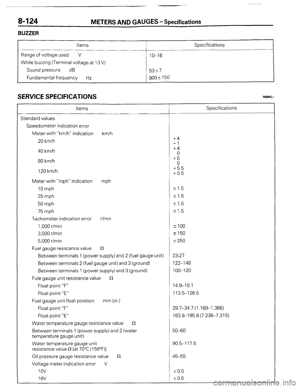
8-124
BUZZER METERS AND
GAUGES - Specifications
Items
Range of voltage used V
While buzzing (Terminal voltage at 13 V)
Sound pressure dB
Fundamental frequency Hz IO-16
53-7
goo* 150 Specifications
SERVICE SPECIFICATIONS
Items Specifications
Standard values
Speedometer indication error
Meter with “km/h” indication km/h
20 km/h f4
-1
40 km/h +4
0
80 km/h +5
0
120 km/h +5.5
+0.5
Meter with “mph” indication
mph
10 mph +- 1.5
25 mph + 1.5
50 mph +I.5
75 mph k 1.5
Tachometer indication error r/min
1,000 r/min *IO0
3,000 r/min +150
5,000 r/min f 250
Fuel gauge resistance value R
Between terminals 1 (power supply) and 2 (fuel gauge unit) 23-27
Between terminals 2 (fuel gauge unit) and 3 (ground) 122-l 48
Between terminals 1 (power supply) and 3 (ground) 100-l 20
Fule gauge unit resistance value R
Float point “F” 14.9-19.1
Float point “E” 113.5-l 26.5
Fuel gauge unit float position mm (in.)
Float point “F” 29.7-34.7 (1.169-l .366)
Float point “E” 183.8-185.8(7.236-7.315)
Water temperature gauge resistance value R
Between terminals 1 (power supply) and 2 (water 50-60
temperature gauge unit)
Water temperature gauge unit 90.5-I 17.5
resistance value R [at 70°C (158”F)l
Oil pressure gauge resistance value 1R 45-55
Voltage meter indication error V
IOV to.5
16V k 0.5
( ST6 Revision
-7
Page 148 of 284
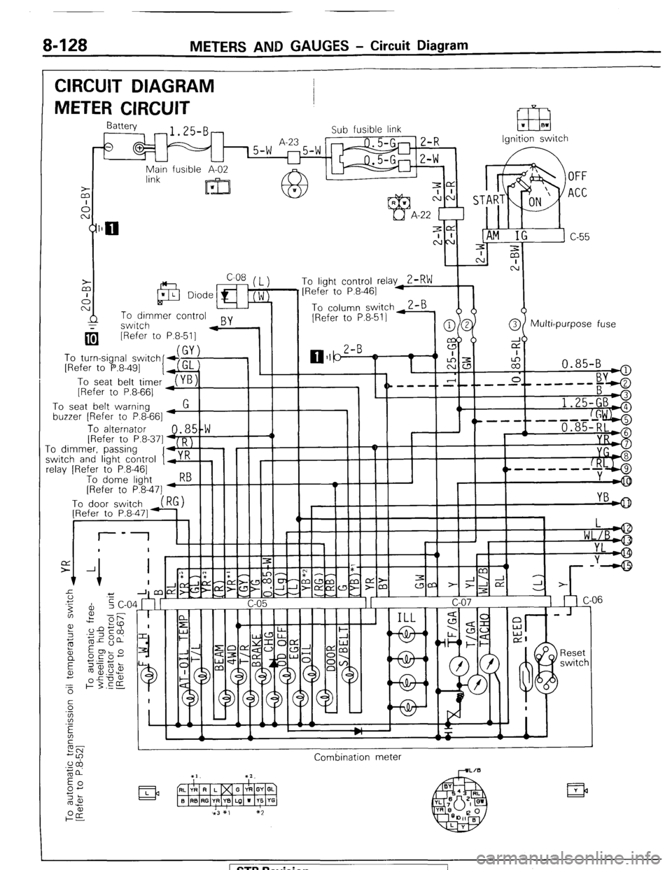
8-128 METERS AND GAUGES - Circuit Diagram
CIRCUIT DIAGRAM
METER CIRCUIT
Ignition switch
q [Refer to
To turn-signal switch
[Refer to P.8-491
I
To seat belt timer
[Refer to P.8-661 P.8-511 -
To seat belt warning
buzzer [Refer to P.8-661
1.25-GBA
, ^.
To alternator 48,5!W III -1 / 1 , 1 '----f--d+ii$$j IRefer to P.8.371 D I
.I_ -0 dimmkr, passinq
‘I+,:’ ! I I I II -I
I r I I I II YI
;witch and light control y K
clay [Refer to P.8-461
To dome liaht 5--hIIII I
----m-w-
[Refer to P&47] -w
Combination meter
( STB Revision
Page 154 of 284
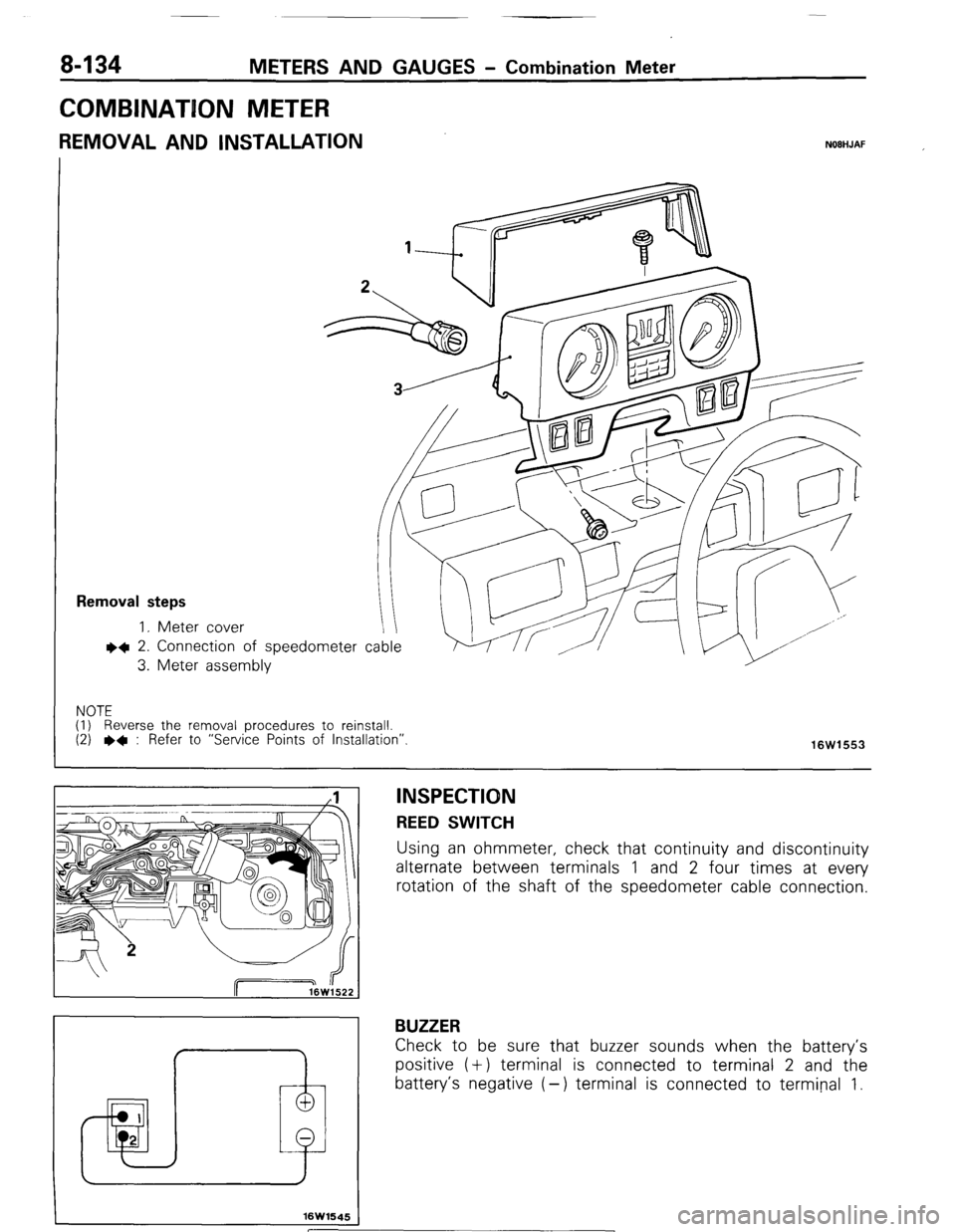
8-134 METERS AND GAUGES - Combination Meter
COMBINATION METER
REMOVAL AND INSTALLATION NOBHJAF
Removal steps
1. Meter cover
l 4 2. Connection
3. Meter asset of speedometer cable
nbly
NOTE
(I) Reverse the removal procedures to reinstall.
(2)
l + : Refer to “Service Points of Installation”.
16W1553
I 1 I
I
f
16W1645
INSPECTION REED SWITCH
Using an ohmmeter, check that continuity and discontinuity
alternate between terminals 1 and 2 four times at every
rotation of the shaft of the speedometer cable connection.
BUZZER
Check to be sure that buzzer sounds when the battery’s
positive (+) terminal is connected to terminal 2 and the
battery’s negative (-) terminal is connected to terminal 1.
[ STB Revision
Page 156 of 284
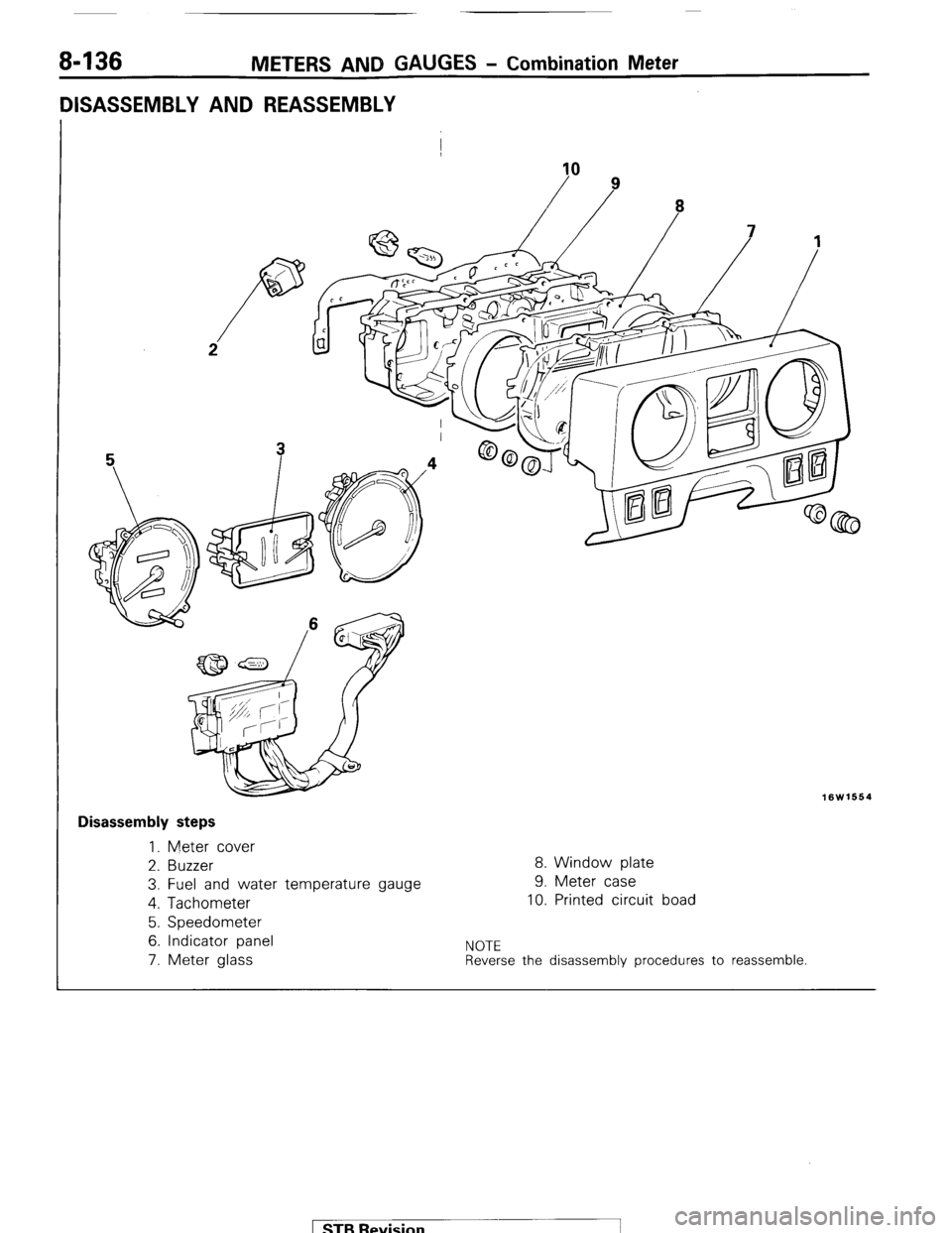
8-136 METERS AND GAUGES - Combination Meter
DISASSEMBLY AND REASSEMBLY
I
10
16W1664
I Disassembly steps
1. Meter cover
2. Buzzer
8. Window plate
3. Fuel and water temperature gauge 9. Meter case
4. Tachometer
10. Printed circuit boad
5. Speedometer
6. Indicator panel
NOTE 7. Meter glass Reverse the disassembly procedures to reassemble. 1 STB Revision -1