glove box MITSUBISHI MONTERO 1987 1.G Workshop Manual
[x] Cancel search | Manufacturer: MITSUBISHI, Model Year: 1987, Model line: MONTERO, Model: MITSUBISHI MONTERO 1987 1.GPages: 284, PDF Size: 14.74 MB
Page 245 of 284
HEATERS - Heater Control 24-9
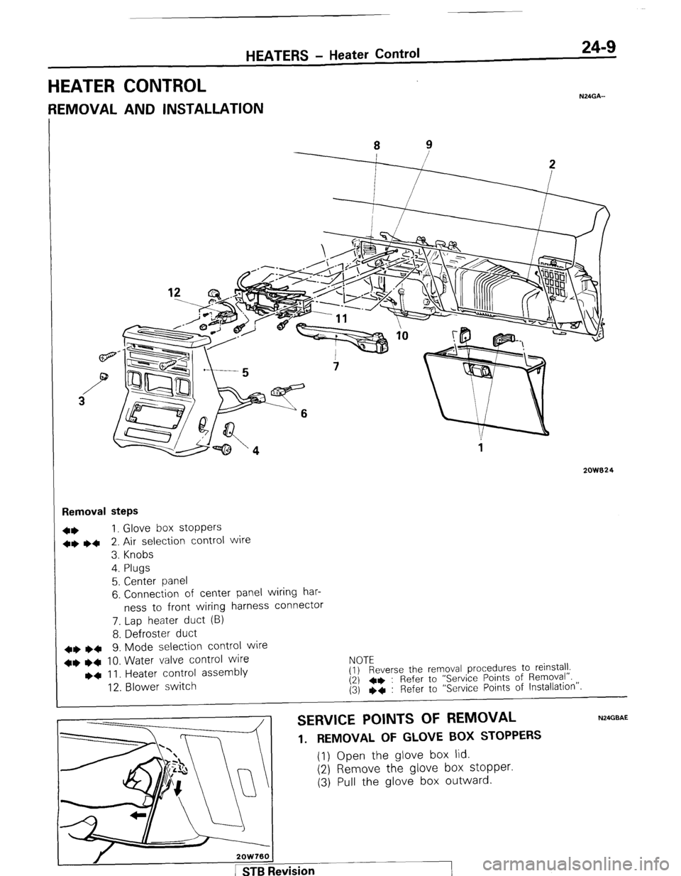
HEATER CONTROL
N24GA-
REMOVAL AND INSTALLATION
2QW824
Removal steps
4+ 1. Glove box stoppers
++ ~~ 2. Air selection control wire
3. Knobs
4. Plugs
5. Center panel
6. Connection of center panel wiring har-
ness to front wiring harness connector
7. Lap heater duct (B)
8. Defroster duct
++
l + 9. Mode selection control wire
++
l + 10. Water valve control wire
l a II. Heater control assembly
12. Blower switch EyTEeverse the removal procedures to reinstall.
(2) 4+ : Refer to “Service Points of Removal”.
(3) eq : Refer to “Service Points of Installation”.
SERVICE POINTS OF REMOVAL N24GBAE
1. REMOVAL OF GLOVE BOX STOPPERS (1) Open the glove box lid.
(2) Remove the glove box stopper. (3) Pull the glove box outward.
Page 250 of 284
24-14 HEATERS + Blower Assembly
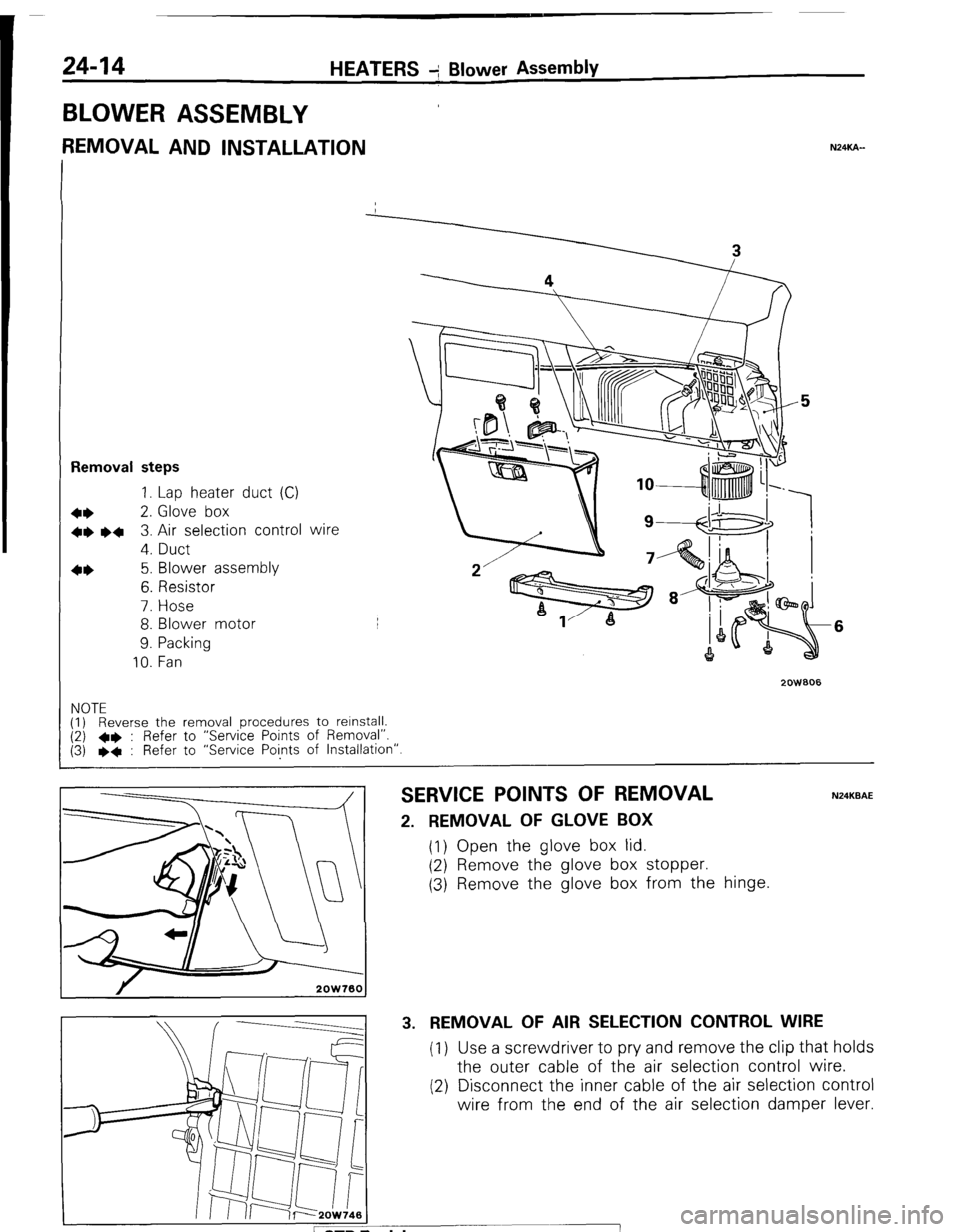
BLOWER ASSEMBLY
REMOVAL AND INSTALLATION NXKA-
Removal steps
1. Lap heater duct (C)
+* 2. Glove box
+e l + 3. Air selection control wire
4. Duct
4* 5. Blower assembly
6. Resistor
7. Hose
8. Blower motor
9. Packing
10. Fan
2oWBO6
6
NOTE
(1) Reverse the removal procedures to relnstall. (2) l * : Refer to “Service Points of Removal”.
(3) l * : Refer to “Service Points of Installation”.
SERVICE POINTS OF REMOVAL N24KBAE
2. REMOVAL OF GLOVE BOX
(1) Open the glove box lid.
(2) Remove the glove box stopper.
(3) Remove the glove box from the hinge.
3. REMOVAL OF AIR SELECTION CONTROL WIRE
(1) Use a screwdriver to pry and remove the clip that holds
the outer cable of the air selection control wire.
(2) Disconnect the inner cable of the air selection control
wire from the end of the air selection damper lever.
Page 253 of 284
HEATERS - Ventilators 24-17
2OW75l
2OW759
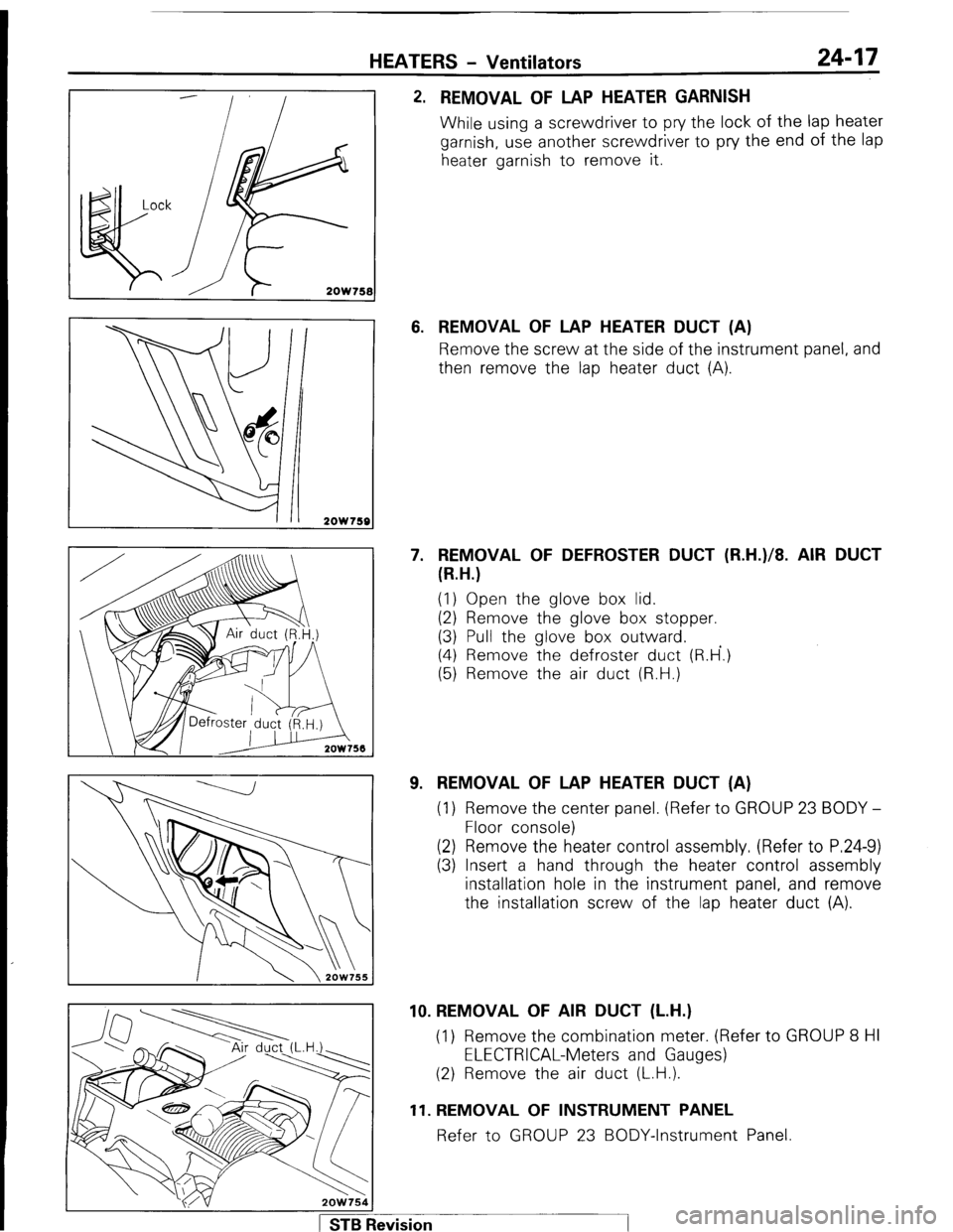
2. REMOVAL OF LAP HEATER GARNISH
While using a screwdriver to pry the lock of the lap heater
garnish, use another screwdriver to pry the end of the lap
heater garnish to remove it.
6. REMOVAL OF LAP HEATER DUCT (A)
Remove the screw at the side of the instrument panel, and
then remove the lap heater duct (A).
7. REMOVAL OF DEFROSTER DUCT (R.H.)/8. AIR DUCT
(R.H.)
(1) Open the glove box lid.
(2) Remove the glove box stopper.
(3) Pull the glove box outward.
(4) Remove the defroster duct (R.H’.)
(5) Remove the air duct (R.H.)
9. REMOVAL OF LAP HEATER DUCT (A)
(1) Remove the center panel. (Refer to GROUP 23 BODY -
Floor console)
(2) Remove the heater control assembly. (Refer to P.24-9)
(3) Insert a hand through the heater control assembly
installation hole in the instrument panel, and remove
the installation screw of the lap heater duct (A).
1 STB Revision 10. REMOVAL OF AIR DUCT (L.H.)
(1) Remove the combination meter. (Refer to GROUP 8 HI
ELECTRICAL-Meters and Gauges)
(2) Remove the air duct (L.H.).
11. REMOVAL OF INSTRUMENT PANEL
Refer to GROUP 23 BODY-Instrument Panel.
Page 278 of 284
24-42 AIR-CONDITIONING - Air Conditioner Switch
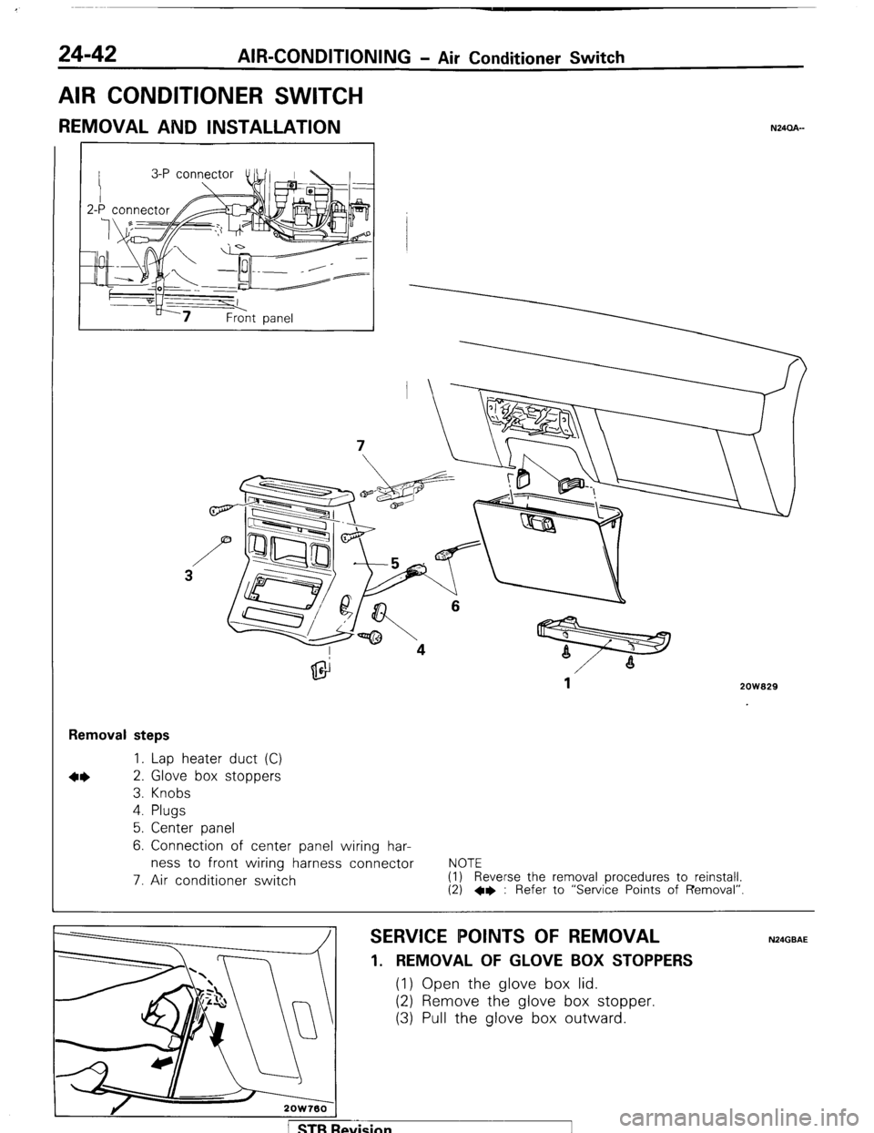
AIR CONDITIONER SWITCH
REMOVAL AND INSTALLATION N24CLA-
2ow929
Removal steps
1. Lap heater duct (C)
2. Glove box stoppers
3. Knobs
4. Plugs
5. Center panel
6. Connection of center panel wiring har-
ness to front wiring harness connector
7. Air conditioner switch
NOTE
(1) Reverse the removal procedures to reinstall. (2) +e : Refer to “Service Points of Removal”
SERVICE POINTS OF REMOVAL
1. REMOVAL OF GLOVE BOX STOPPERS
(1) Open the glove box lid.
(2) Remove the glove box stopper.
(3) Pull the glove box outward.
1 STB Revision
Page 279 of 284
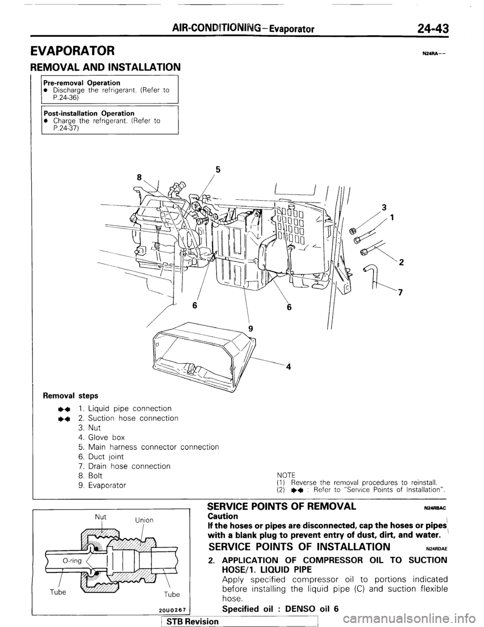
AIR-CONDBTIONI G - Evaporator 24-43
EVAPORATOR
REMOVAL AND INSTALLATION
N24RA--
Pre-removal Operation
l
Discharge the refrigerant. (Refer to
P.24-36) Removal
steps ~~ 1. Liquid pipe connection
l + 2. Suction hose connection
3. Nut
4. Glove box
5. Main harness connector connection
6. Duct joint
7. Drain hose connection
8. Bolt
9. Evaporator
NOTE
(I) Reverse the removal procedures to reinstall.
(2) l
* : Refer to “Service Points of Installation”.
Nut
I Union
/
2OUO267
SERVICE POINTS OF REMOVAL Caution N24MAC If the hoses or pipes are disconnected, cap the hoses or pipes:
with a blank plug to prevent entry of dust, dirt, and water.
SERVICE POINTS OF INSTALLATION N24AOAE 2. APPLICATION OF COMPRESSOR OIL TO SUCTION
HOSE/l. LIQUID PIPE
Apply specified compressor oil to portions indicated
before installing the liquid pipe (C) and suction flexible
hose.
Specified oil : DENS0 oil 6
!vision