MITSUBISHI MONTERO 2003 Service User Guide
MONTERO 2003
MITSUBISHI
MITSUBISHI
https://www.carmanualsonline.info/img/19/57329/w960_57329-0.png
MITSUBISHI MONTERO 2003 Service User Guide
Page 149 of 1000
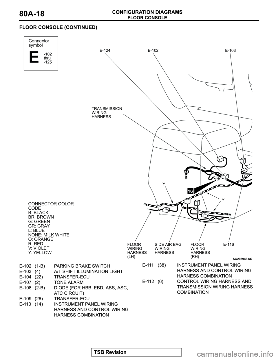
AC203946
Connector
symbol
-102
thru
-125
E
CONNECTOR COLOR
CODE
B: BLACK
BR: BROWN
G: GREEN
GR: GRAY
L: BLUE
NONE: MILK WHITE
O: ORANGE
R: RED
V: VIOLET
Y: YELLOW
E-124
Y
Y E-102 E-103
E-116
AC
16
TRANSMISSION
WIRING
HARNESS
FLOOR
WIRING
HARNESS
(RH) SIDE AIR BAG
WIRING
HARNESS FLOOR
WIRING
HARNESS
(LH)
Page 150 of 1000
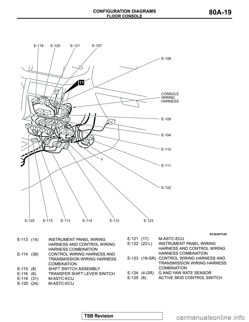
AC203875AC
Y E-120 E-121 E-107
E-108
E-109
E-110
E-111
E-112 E-113 E-114 E-115
11
E-119
E-125 E-123
E-122
E-104
CONSOLE
WIRING
HARNESS
Page 151 of 1000
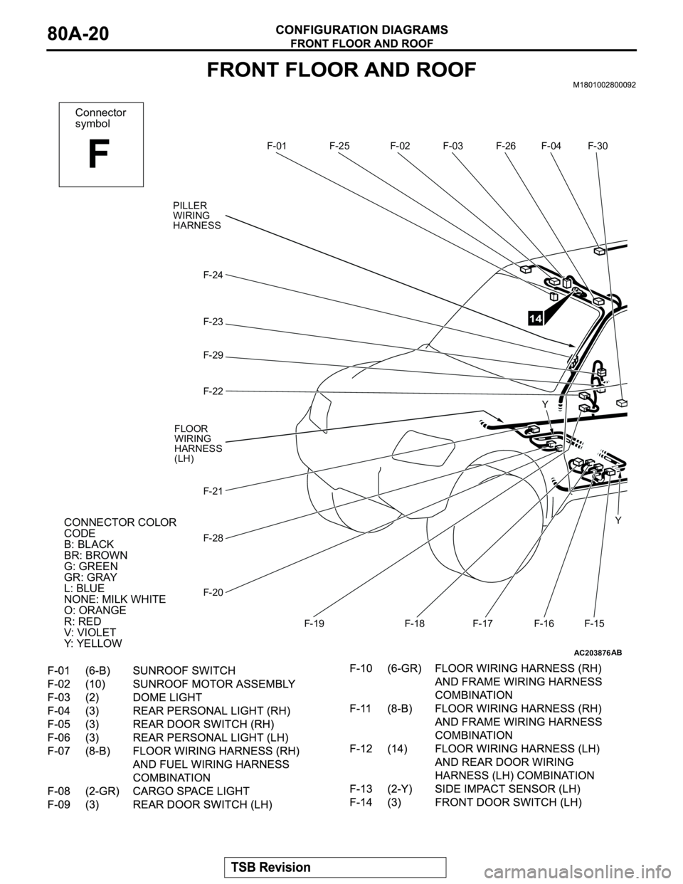
AC203876
Connector
symbol
F
F-01F-02 F-03 F-04
F-15 F-16 F-17 F-18 F-19 F-20 F-21 F-22 F-23 F-24
CONNECTOR COLOR
CODE
B: BLACK
BR: BROWN
G: GREEN
GR: GRAY
L: BLUE
NONE: MILK WHITE
O: ORANGE
R: RED
V: VIOLET
Y: YELLOWY Y
AB
F-28
F-29
F-25F-26
14
F-30
PILLER
WIRING
HARNESS
FLOOR
WIRING
HARNESS
(LH)
Page 152 of 1000
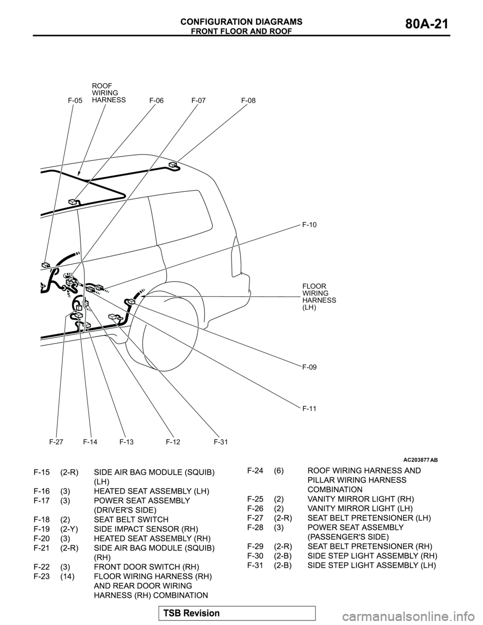
AC203877AB
F-05 F-06 F-07 F-08
F-09 F-10
F-31 F-12 F-13 F-14
F-27
F-11
ROOF
WIRING
HARNESS
FLOOR
WIRING
HARNESS
(LH)
Page 153 of 1000
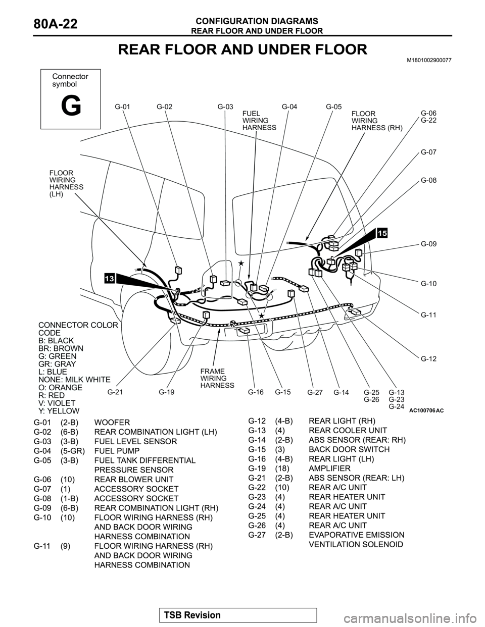
AC100706
Connector
symbol
GG-01
AC
G-02 G-03 G-04 G-05
G-06
G-22
G-07
G-08
G-09
G-10
G-11
G-12
G-13
G-23
G-24 G-25
G-26 G-14 G-15 G-16 G-19 G-21
CONNECTOR COLORCODEB:BLACKBR:BROWNG:GREENGR:GRAYL:BLUENONE:MILK WHITEO:ORANGER:REDV:VIOLETY:YELLOW
CONNECTOR COLOR
CODE
B: BLACK
BR: BROWN
G: GREEN
GR: GRAY
L: BLUE
NONE: MILK WHITE
O: ORANGE
R: RED
V: VIOLET
Y: YELLOW
13
15
G-27 FUEL
WIRING
HARNESS
FLOOR
WIRING
HARNESS (RH)
FRAME
WIRING
HARNESS
FLOOR
WIRING
HARNESS
(LH)
Page 154 of 1000
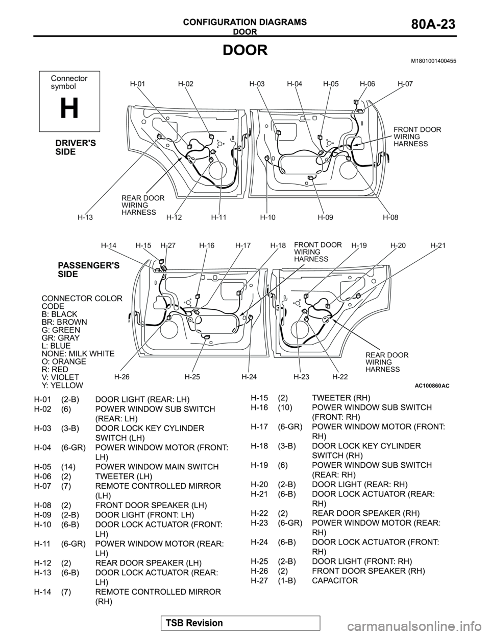
AC100860
Connector
symbol
H
H-01
AC
DRIVER'S
SIDE
PASSENGER'S
SIDE
H-02 H-03 H-04 H-05 H-06 H-07
H-08 H-09 H-10 H-11 H-12 H-13
H-14 H-15 H-27 H-16 H-17 H-18 H-19 H-20 H-21
H-22
H-23H-24 H-25 H-26
CONNECTOR COLOR
CODE
B: BLACK
BR: BROWN
G: GREEN
GR: GRAY
L: BLUE
NONE: MILK WHITE
O: ORANGE
R: RED
V: VIOLET
Y: YELLOW
REAR DOOR
WIRING
HARNESS
FRONT DOOR
WIRING
HARNESS REAR DOOR
WIRING
HARNESS
FRONT DOOR
WIRING
HARNESS
Page 155 of 1000
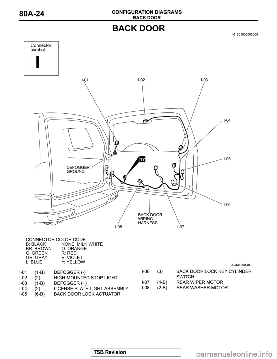
ACX00245
Connector
symbol
I
I-01
AC
CONNECTOR COLOR CODE
B: BLACK
BR: BROWN
G: GREEN
GR: GRAY
L: BLUENONE: MILK WHITE
O: ORANGE
R: RED
V: VIOLET
Y: YELLOW
DEFOGGER
GROUNDI-02 I-03
I-04
I-05
I-06
I-07 I-08
17
BACK DOOR
WIRING
HARNESS
Page 483 of 1000
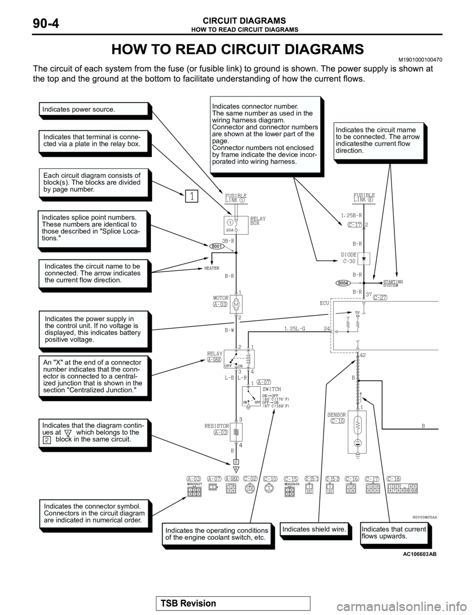
AC106603
Indicates power source.
Indicates that terminal is conne-
cted via a plate in the relay box.
Each circuit diagram consists of
block(s). The blocks are divided
by page number.
Indicates splice point numbers.
These numbers are identical to
those described in "Splice Loca-
tions."
Indicates the circuit name to be
connected. The arrow indicates
the current flow direction.
Indicates the power supply in
the control unit. If no voltage is
displayed, this indicates battery
positive voltage.
An "X" at the end of a connector
number indicates that the conn-
ector is connected to a central-
ized junction that is shown in the
section "Centralized Junction."
Indicates the connector symbol.
Connectors in the circuit diagram
are indicated in numerical order.
Indicates the operating conditions
of the engine coolant switch, etc.
Indicates connector number.
The same number as used in the
wiring harness diagram.
Connector and connector numbers
are shown at the lower part of the
page.
Connector numbers not enclosed
by frame indicate the device incor-
porated into wiring harness.
Indicates the circuit mame
to be connected. The arrow
indicatesthe current flow
direction.
Indicates that the diagram contin-
ues at which belongs to the
block in the same circuit.
AB
Indicates shield wire.Indicates that current
flows upwards.
Page 484 of 1000
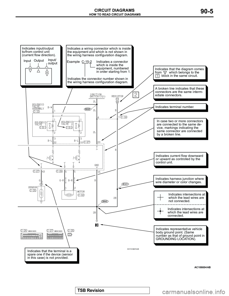
AC106604
Indicates that the terminal is a
spare one if the device (sensor
in this case) is not provided.
Indicates representative vehicle
body ground point. (Same
number as that of ground point in
GROUNDING LOCATION).
Indicates harness junction where
wire diameter or color changes.
In case two or more connectors
are connected to the same de-
vice, markings indicating the
same connector are connected
by a broken line.
Indicates terminal number.
A broken line indicates that these
connectors are the same interm-
ediate connectors.
Indicates intersections at
which the lead wires are
not connected.
Indicates intersections at
which the lead wires are
connected.
Indicates input/output
to/from control unit
(current flow direction).
InputOutputInput/
output
Indicates current flow downward
or upward as controlled by the
control unit.
AB
Indicates that the diagram comes
from which belongs to the
block in the same circuit.
Indicates a wiring connector which is inside
the equipment and which is not shown in
the wiring harness configuration diagram.
Example C-15-2
Indicates a connector
which is inside the
equipment, numbered
in order starting from 1.
Indicates the connector number shown in
the wiring harness configuration diagram.
Page 490 of 1000
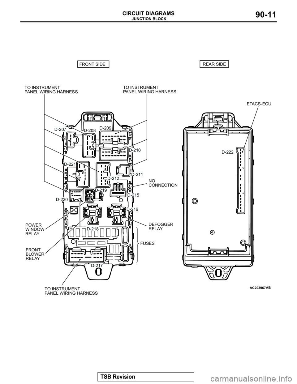
AC203967AB
D-207
D-208D-209
D-210
D-211D-212
D-216
D-217
D-218
D-219
D-220
D-221
D-215
D-222 TO INSTRUMENT
PANEL WIRING HARNESS
NO
CONNECTION
DEFOGGER
RELAY
FRONT
BLOWER
RELAY POWER
WINDOW
RELAY
FUSES
ETACS-ECU
TO INSTRUMENT
PANEL WIRING HARNESSTO INSTRUMENT
PANEL WIRING HARNESS
FRONT SIDEREAR SIDE