clock MITSUBISHI OUTLANDER 2015 3.G Owners Manual
[x] Cancel search | Manufacturer: MITSUBISHI, Model Year: 2015, Model line: OUTLANDER, Model: MITSUBISHI OUTLANDER 2015 3.GPages: 446, PDF Size: 59.52 MB
Page 23 of 446
Filling the fuel tank 3-4 General information
3
All-wheel drive vehicles: 15.8 gal (60 L) Front-wheel drive vehi
cles: 16.6 gal (63 L)
1. Before filling with fuel, stop the engine. 2. The fuel tank filler is located on the rear driver side of your vehicle. The fuel tank filler door can be openedfrom inside the vehicle with the fuel tank filler door release lever located at the left side of the driver’s seat. 3. Open the fuel tank filler pipe by slowly turning the fuel tank filler cap counter- clockwise.
Before removing the fuel tank filler cap, be sure to get rid of your body’s staticelectricity by touching a metal part of thecar or fuel pump. Any
static electricity on
your body could create a spark that ignites fuel vapor. Perform the whole
refueling process
(opening the fuel tank filler door, remov-ing the fuel cap, etc.) by yourself; do not let any other
person near the fuel tank
filler. If you allowed
a person to help you
and that person was ca
rrying static elec-
tricity, fuel vapor could be ignited. Do not move away from
the fuel tank filler
until refueling is fi
nished. If you moved
away and did somethin
g else (for example,
sitting on a seat) part-way through the refueling process, you could pick up a fresh charge of st
atic electricity.
Be careful not to inhale fuel vapor. Fuel contains toxic substances. Keep the doors and wi
ndows closed while
refueling the vehicle. If they were open,fuel vapor could ge
t into the cabin.
Fuel tank capacity
WA R N I N G
Refueling
1- Remove 2- CloseWA R N I N G Since the fuel system may be under pres- sure, remove the fuel tank filler capslowly. This relieves
any pressure or vac-
uum that might have built up in the fuel tank. If the cap is venting vapor or if youhear a hissing sound, wait until the sound stops before removing the cap. Otherwise, fuel may spray out, in
juring you or others.
NOTE
While filling with fuel
, hang the fuel cap on
the hook (A) located on the inside surface ofthe fuel tank filler door.
BK0211800US.book 4 ページ 2014年3月12日 水曜日 午後2時42分
Page 24 of 446
Modifications to and racing of your vehicle
General information 3-5
3
4. Fueling correctly depends mainly on cor- rect handling of the fuel filler nozzle. Donot tilt the nozzle. Insert the nozzle in the fuel tank filler port as far as it goes. 5. When the nozzle stops automatically, do not add more fuel.
6. To re-install, turn the fuel tank filler pipe cap slowly clockwise until you hear click-ing sounds, then gently push the fuel tank filler door closed.
N00301600152
This vehicle should not be modified withnon-Mitsubishi Motors
genuine parts. Mit-
subishi Motors desi
gns and manufactures
high quality vehicles
with an emphasis on
safety and durability.
Modifications using
non-Mitsubishi Motors genuine parts mayaffect the performance,
safety and/or durabil-
ity of your vehicle, a
nd may violate applica-
ble state and/or fe
deral regulations.
DAMAGE OR PERFORMANCE PROB- LEMS RESULTING FROM MODIFICA- TIONS TO OR RACING OF YOURVEHICLE ARE NOT COVERED UNDER WA R R A N T Y. Examples of modifications to your vehicle that can cause damage or performance prob-lems include the following: Failure to use Mits
ubishi Motors genuine
parts Failure to use required fuel and fluids Failure to use proper
size tires and wheels
Modification of the fu
el, intake, exhaust,
emission, suspension,
engine, drive train
or electrical wiring systems
CAUTION Your vehicle can only be operated using unleaded gasoline. Seri
ous engine and cata-
lytic converter damage will result if leaded gasoline is filled into these vehicles, andconsequently, this must
never be attempted.
CAUTIONTo avoid fuel spillage
and overfilling, do not
“top-off” the fuel tank. Spilled fuel could discolor, stain, or cr
ack the vehicle’s paint-
work. If fuel spills on the paintwork, wipe it off with a soft cloth.
WA R N I N G Make sure the fuel tank filler cap is securely closed. If the fuel cap were loose,fuel could leak, re
sulting in a fire.
CAUTIONIf you need to replace th
e fuel tank filler cap,
use only the cap specified for your model vehicle.NOTE
If the fuel tank filler cap is not tight while driving, the engine
malfunction indicator
(“SERVICE ENGINE SOON” or “Check engine light”) may come on when theonboard diagnostic (OBD) system performs a self check. Always tighten the fu
el tank filler cap until
you hear at least 3 clicks. The indicator will go of
f after several driving
cycles. If the indicato
r does not go off, con-
tact your authorized
Mitsubishi Motors
dealer or a repair faci
lity of your choice as
soon as possible.
Modifications to and racing of your vehicle
BK0211800US.book 5 ページ 2014年3月12日 水曜日 午後2時42分
Page 157 of 446
4-wheel drive operation 5-80 Features and controls
5
N00576700021
While the drive mode is in the “NORMAL” position, if the ECO mode switch is switchedON, the drive mode
will be changed to
“AWC ECO” mode. If the ECO mode switch is switched OFF, thedrive mode will be returned to “NORMAL” mode. Refer to the “ECO mode switch” on page 5-177.
N00530601179
Your vehicle has been
designed primarily for
use on pavement. But its unique 4 -wheel drive system allowsyou to occasionally travel on unpaved roads, to campgrounds, picnic
sites, and similar
locations.Not only does this ensure better handling on dry, paved roads but al
so permits better trac-
tion when driving on slippery, wet or snow- covered roads and when moving out of mud.But it is not suitable for heavy off road use or towing in rough conditions. It is particularly im
portant to note that 4-
wheel drive may not gi
ve sufficient hill
climbing ability and e
ngine braking on steep
slopes. You should try to avoid driving onsteep slopes. Also, you must exercise caution when driving on sand and mud and when driving through water because sufficient traction may not be available in certain circumstances.Please avoid driving the vehicle through areas where the tires may get stuck in deep sand or mud.
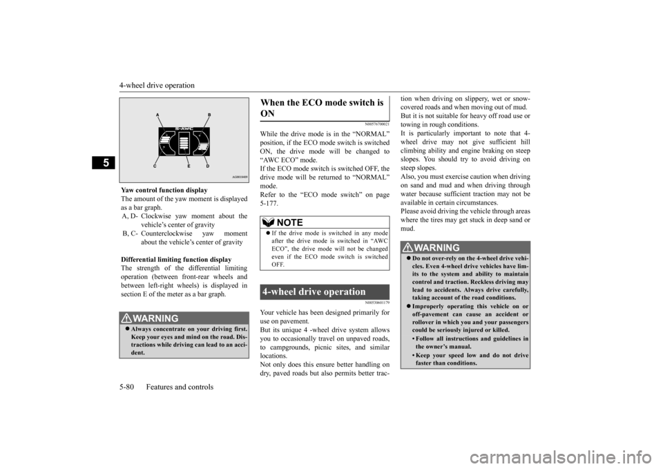
Yaw control function display The amount of the yaw moment is displayed as a bar graph. A, D- Clockwise yaw moment about the
vehicle’s center of gravity
B, C- Counterclockwise yaw moment
about the vehicle’s
center of gravity
Differential limiting
function display
The strength of the differential limitingoperation (between front-rear wheels and between left-right whee
ls) is displayed in
section E of the me
ter as a bar graph.
WA R N I N GAlways concentrate on
your driving first.
Keep your eyes and mi
nd on the road. Dis-
tractions while driving
can lead to an acci-
dent.
When the ECO mode switch is ON
NOTE
If the drive mode is switched in any mode after the drive mode is switched in “AWCECO”, the drive mode will not be changed even if the ECO mode switch is switched OFF.
4-wheel drive operation
WA R N I N G Do not over-rely on th
e 4-wheel drive vehi-
cles. Even 4-wheel drive vehicles have lim- its to the system and ability to maintaincontrol and traction.
Reckless driving may
lead to accidents. Al
ways drive carefully,
taking account of the road conditions. Improperly operating
this vehicle on or
off-pavement can cause an accident orrollover in which you
and your passengers
could be seriously
injured or killed.
• Follow all instructions and guidelines in the owner’s manual.• Keep your speed low and do not drivefaster than conditions.
BK0211800US.book 80 ページ 2014年3月12日 水曜日 午後2時42分
Page 244 of 446
Warning lights
Features and controls 5-167
5
N00520300147 N00520401536
This light comes on when the ignition switch is turned to the “ON” position (engine off) or the operation mode is put in ON.When the engine is started, the light should go off a few seconds later. A warning is also displayed in the multi information display. The warning light also illuminates after start- ing the engine under the following condi-tions. When the parking brake is still applied. When the brake fluid level is low. When the brake system circuit is not working properly.
When the vehicle is moving at more than 5 mph (8 km/h) and parking brake applied, a buzzer will sound to inform the driver that theparking brake is not properly release. Before driving, be sure
that the parking brake
is fully released and
brake warning light is
off.
N00520501814
This indicator is a part
of the onboard diag-
nostic (OBD) system which monitors the emissions, engine control system or auto- matic transaxle cont
rol system/continuously
variable transmission
(CVT) control system.
If a problem is detected in one of these sys- tems, this indicator illuminates or flashes. When the ignition switch is turned to the “ON” position or the operation mode is put inON, this indicator
normally comes on and
goes off after the engine has started. This indicator will come on if the fuel tank filler cap is not properly tightened. If thisindicator comes on and stays on after refuel- ing, stop the engine and check that the cap is properly tightened. (Turn the cap clockwiseuntil you hear clicking sounds.) If this indicator does not go off after several seconds or lights up while driving, have thesystem checked as soon as possible at an authorized Mitsubishi Motors dealer or a repair facility
of your choice.
Warning lights Brake warning light and buzzer
CAUTIONIf the brake warning light and the Anti-lock braking system warning
light are illuminated
at the same time, the braking force distribu-tion function will not ope
rate, so the vehicle
may be destabilized during sudden braking under the following conditions.• When the brake warning light does not goout even when the parking brake isreleased.• When the brake warning light stays onwhile driving.• If the above occurs, avoid sudden brakingand high-speed driving. Park the vehicle in a safe place, and contact an authorized Mit- subishi Motors dealer or a repair facility ofyour choice as soon as possible.
The vehicle should be brought to a halt in the following manner when brake performance is deteriorated.• Confirm that the vehicle slows down whenyou press down on the brake pedal harder than usual. In some cases, the brake pedalmay go all the way to the floor.• Should the brakes fail, use engine brakingto reduce your speed and slowly apply the parking brake. Depress the brake peda
l to illuminate the
stop lights to alert
the vehicles
behind you.
Engine malfunction indicator (“SERVICE ENGINE SOON” or “Check engine light”)
BK0211800US.book 167 ページ 2014年3月12日 水曜日 午後2時42分
Page 340 of 446
Operation Keys
Comfort controls 7-25
7
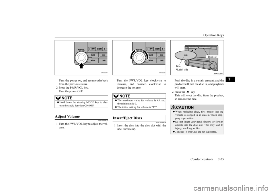
Turn the power on, and resume playback from the previous status.2. Press the PWR/VOL key. Turn the power OFF.
N00716500023
1. Turn the PWR/VOL key to adjust the vol-ume.
Turn the PWR/VOL key clockwise to increase, and counter- clockwise todecrease the volume.
N00716600024
1. Insert the disc into
the disc slot with the
label surface up.
Push the disc in a certain amount, and the product will pull the disc in, and playbackwill start. 2. Press the key. This will eject the disc from the product, so remove the disc.
NOTE
Hold down the steering MODE key to also turn the audio function ON/OFF.
Adjust Volume
NOTE
The maximum value for volume is 45, and the minimum is 0. The initial setting for volume is “17”.
Insert/Eject Discs
CAUTIONWhen replacing discs, first ensure that the vehicle is stopped in an
area in which stop-
ping is permitted. Do not insert your hand, fingers, or foreign objects into the disc slot. This may lead toinjury, smoking, or fire. 3 inches (8 cm) CDs are not supported.Disc * Label side
Disc slot
BK0211800US.book 25 ページ 2014年3月12日 水曜日 午後2時42分
Page 343 of 446
Listen to Radio 7-28 Comfort controls
7
N00716900027
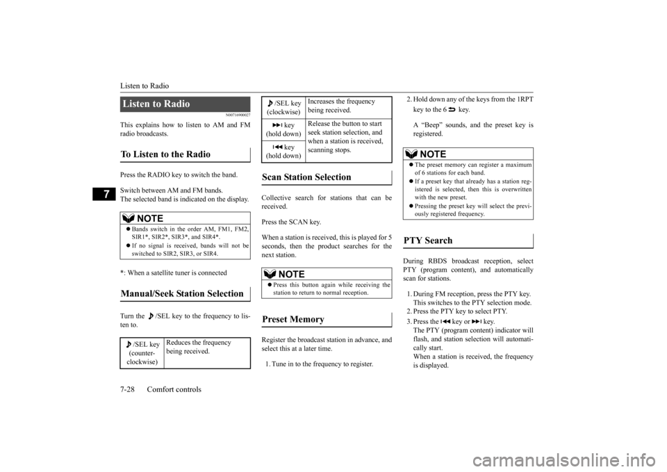
This explains how to listen to AM and FM radio broadcasts. Press the RADIO key to switch the band. Switch between AM and FM bands. The selected band is indicated on the display. *: When a satellite
tuner is connected
Turn the /SEL key to the frequency to lis- ten to.
Collective search for stations that can be received. Press the SCAN key.When a station is received, this is played for 5 seconds, then the product searches for the next station. Register the broadcast st
ation in advance, and
select this at a later time. 1. Tune in to the frequency to register.
2. Hold down any of the keys from the 1RPT key to the 6 key. A “Beep” sounds, and the preset key is registered.
During RBDS broadcast
reception,
select
PTY (program conten
t), and automatically
scan for stations. 1. During FM reception,
press the PTY key.
This switches to the PTY selection mode. 2. Press the PTY key to select PTY. 3. Press the key or key. The PTY (program cont
ent) indicator will
flash, and station selection will automati- cally start.When a station is received, the frequency is displayed.
Listen to Radio To Listen to the Radio
NOTE
Bands switch in the order AM, FM1, FM2, SIR1*, SIR2*, SIR3*, and SIR4*. If no signal is receiv
ed, bands will not be
switched to SIR2, SIR3, or SIR4.
Manual/Seek Station Selection
/SEL key (counter- clockwise)
Reduces the frequency being received.
/SEL key (clockwise)
Increases the frequency being received.
key
(hold down)
Release the button to start seek station selection, and when a station is received, scanning stops.
key
(hold down)Scan Station Selection
NOTE
Press this button again while receiving the station to return
to normal reception.
Preset Memory
NOTE
The preset memory can register a maximum of 6 stations for each band. If a preset key that al
ready has a station reg-
istered is selected, then this is overwritten with the new preset. Pressing the preset ke
y will select the previ-
ously registered frequency.
PTY Search
BK0211800US.book 28 ページ 2014年3月12日 水曜日 午後2時42分
Page 357 of 446
System Settings 7-42 Comfort controls
7
N00718500043
Change system settings
such as product time.
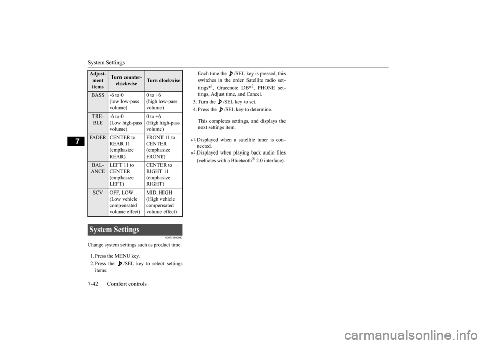
1. Press the MENU key. 2. Press the /SEL key to select settings items.
Each time the /SEL key is pressed, this switches in the order Satellite radio set- tings*
1, Gracenote DB*
2, PHONE set-
tings, Adjust time, and Cancel. 3. Turn the /SEL key to set.4. Press the /SEL key to determine. This completes settings, and displays the next setti
ngs item.
Adjust- ment items
Turn counter- clockwise
Turn clockwise
BASS -6 to 0
(low low-pass volume)
0 to +6 (high low-pass volume)
TRE- BLE
-6 to 0 (Low high-pass volume)
0 to +6 (High high-pass volume)
FADER CENTER to
REAR 11 (emphasize REAR)
FRONT 11 to CENTER (emphasize FRONT)
BAL- ANCE
LEFT 11 to CENTER (emphasize LEFT)
CENTER to RIGHT 11 (emphasize RIGHT)
SCV OFF, LOW
(Low vehicle compensated volume effect)
MID, HIGH (High vehicle compensated volume effect)
System Settings
*1: Displayed when a sate
llite tuner is con-
nected.
*2: Displayed when playi
ng back audio files
(vehicles with a Bluetooth
® 2.0 interface).
BK0211800US.book 42 ページ 2014年3月12日 水曜日 午後2時42分
Page 362 of 446
Antenna
Comfort controls 7-47
7
Here is a list of symptoms, causes and respons
es if you think something
is not working properly.
N00734201494
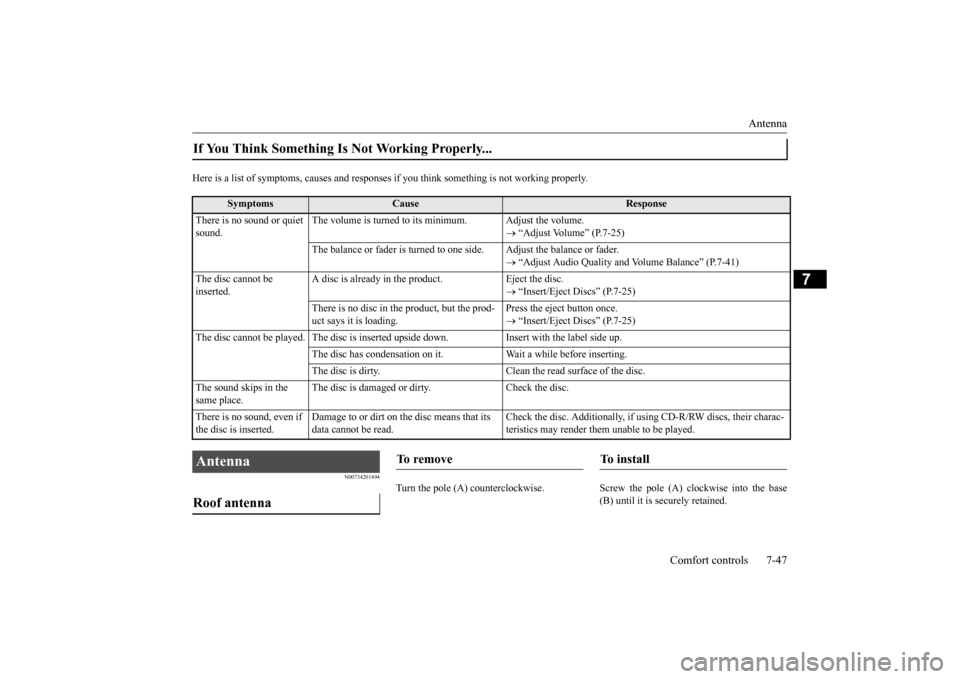
Turn the pole (A) countercl
ockwise. Screw the pole (A) clockwise into the base
(B) until it is securely retained.
If You Think Something Is Not Working Properly...
Symptoms
Cause
Response
There is no sound or quiet sound.
The volume is turned to its minimum. Adjust the volume.
“Adjust Volume” (P.7-25)
The balance or fader is turned to
one side. Adjust the balance or fader.
“Adjust Audio Quality and
Volume Balance” (P.7-41)
The disc cannot be inserted.
A disc is already in the product. Eject the disc.
“Insert/Eject Discs” (P.7-25)
There is no disc in
the product, but the prod-
uct says it is loading.
Press the eject button once. “Insert/Eject Discs” (P.7-25)
The disc cannot be played. The
disc is inserted up
side down. Insert with
the label side up.
The disc has condensation on it
. Wait a while before inserting.
The disc is dirty. Clean the
read surface of the disc.
The sound skips in the same place.
The disc is damaged or dirty. Check the disc.
There is no sound, even if the disc is inserted.
Damage to or dirt on the disc means that its data cannot be read.
Check the disc. Additionally, if using CD-R/RW discs, their charac- teristics may render them
unable to be played.
Antenna Roof antenna
To r e m o v e
To install
BK0211800US.book 47 ページ 2014年3月12日 水曜日 午後2時42分
Page 370 of 446
Jack and tools
For emergencies 8-5
8
6. When you do not see any more steam or spray, open the hood. Look for obviousleaks, such as a split radiator hose. Be careful as components will be hot. Any leak source must be repaired.7. If there is no obvious leak source, check the coolant level in the engine coolant reserve tank. If there is
none, or if it is too
low, slowly add coolant. 8. If the engine coolant reserve tank needs coolant, you will probably also need toadd coolant to the radiator. Do not loosen or remove the radiator cap until the engine has cooled down.
9. Start the engine, a
nd slowly add coolant,
up to the bottom of the filler neck. Use plain water if you have to (and replace itwith the right coolant as soon as possible).
10. Replace the radiator cap and tighten it
fully. Check the engine coolant tempera-ture display on the mu
lti information dis-
play (Color liquid crystal display type) or the high coolant temperature warninglight (Mono-color liqui
d crystal display
type). You can start driving again when the high coolant temperature warningdoes not come on.
11. Have the system inspected by your autho-
rized Mitsubishi Motors
dealer or a repair
facility of your choice.
N00836601389
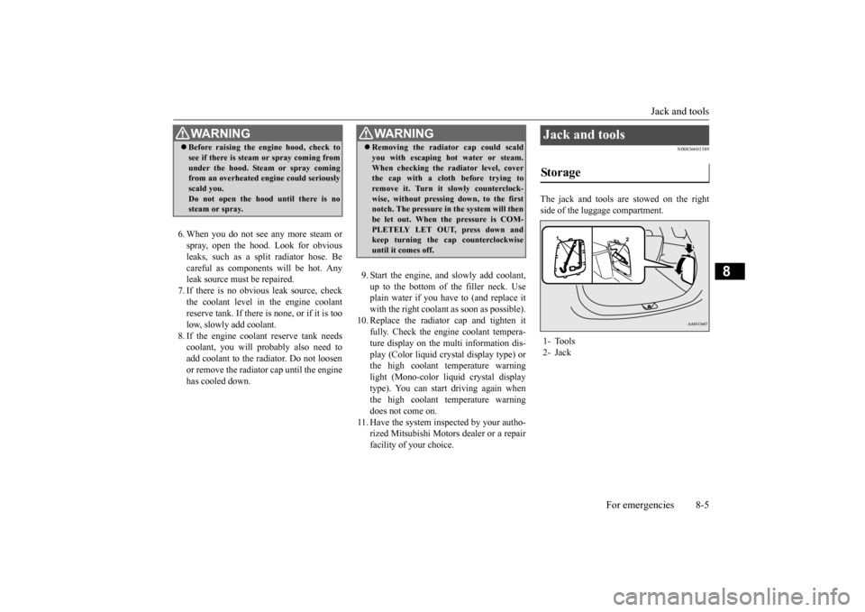
The jack and tools are stowed on the right side of the luggage compartment.
WA R N I N G Before raising the en
gine hood, check to
see if there is steam or spray coming fromunder the hood. Steam or spray comingfrom an overheated en
gine could seriously
scald you. Do not open the hood until there is nosteam or spray.
WA R N I N G Removing the radiat
or cap could scald
you with escaping hot water or steam.When checking the radiator level, coverthe cap with a cloth before trying to remove it. Turn it slowly counterclock- wise, without pressing down, to the firstnotch. The pressure in the system will then be let out. When the pressure is COM- PLETELY LET OUT, press down andkeep turning the cap counterclockwise until it comes off.
Jack and tools Storage 1- Tools 2- Jack
BK0211800US.book 5 ページ 2014年3月12日 水曜日 午後2時42分
Page 373 of 446
How to change a tire 8-8 For emergencies
8
N00849701296
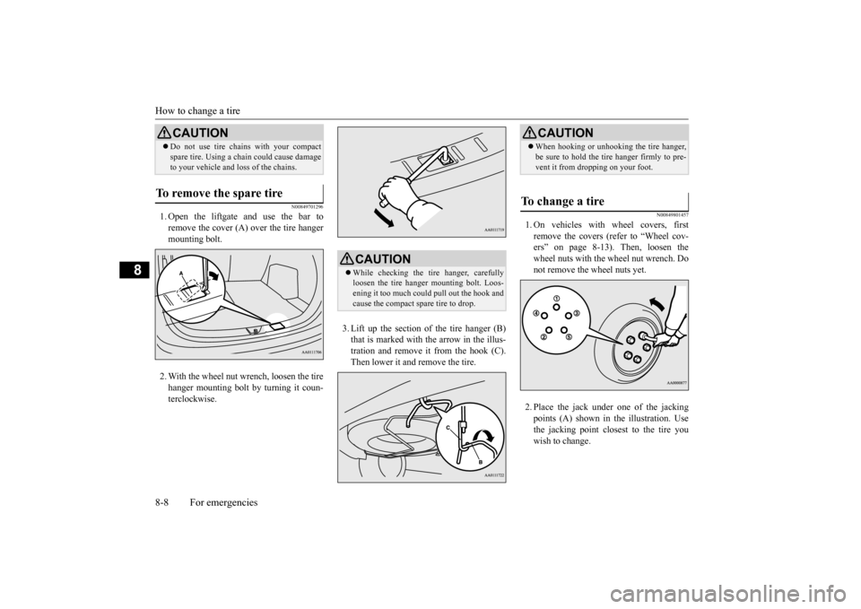
1. Open the liftgate and use the bar to remove the cover (A)
over the tire hanger
mounting bolt. 2. With the wheel nut wrench, loosen the tire hanger mounting bolt by turning it coun- terclockwise.
3. Lift up the section of the tire hanger (B) that is marked with the arrow in the illus-tration and remove it from the hook (C). Then lower it and remove the tire.
N00849801457
1. On vehicles with
wheel covers, first
remove the covers (re
fer to “Wheel cov-
ers” on page 8-13). Then, loosen thewheel nuts with the wheel nut wrench. Do not remove the wheel nuts yet. 2. Place the jack under one of the jacking points (A) shown in the illustration. Use the jacking point closest to the tire you wish to change.
Do not use tire chains with your compact spare tire. Using a ch
ain could cause damage
to your vehicle and loss of the chains.
To remove the spare tire
CAUTION
CAUTION While checking the tir
e hanger, carefully
loosen the tire hanger mounting bolt. Loos-ening it too much could pull out the hook and cause the compact spare tire to drop.
CAUTION When hooking or unhooking the tire hanger, be sure to hold the tire hanger firmly to pre-vent it from dropping on your foot.
To change a tire
BK0211800US.book 8 ページ 2014年3月12日 水曜日 午後2時42分