indicator MITSUBISHI OUTLANDER 2017 3.G Workshop Manual
[x] Cancel search | Manufacturer: MITSUBISHI, Model Year: 2017, Model line: OUTLANDER, Model: MITSUBISHI OUTLANDER 2017 3.GPages: 521, PDF Size: 14.91 MB
Page 204 of 521
Forward Collision Mitigation System (FCM) (if so equipped)
Features and controls 5-123
5
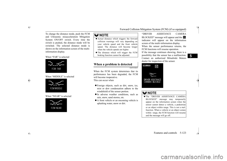
To change the distan
ce mode, push the FCM
and Ultrasonic misacc
eleration
Mitigation
System ON/OFF switch. Every time the switch is pushed, the
distance mode will be
switched. The selected distance mode isshown on the information screen of the multi- information display. When “FAR” is selected When “MIDDLE” is selected When “NEAR” is selected
N00593300035
When the FCM system determines that its performance has been degraded, the FCMwill become inoperative. This can occur when Foreign objects, such as dirt, snow, ice, mist or dew condensation adhere to thewindshield of the sensor portion. In adverse weather
conditions, such as
rain, snow, sand storms, etc. A front vehicle or an oncoming vehicle is splashing water, snow or dirt.
“DRIVER ASSISTANCE CAMERA BLOCKED” message will appear and the indicator will appear
on the information
screen of the multi-information display. When the sensor performance returns, the FCM functions will resume operation.If the message continue
s showing, there is a
possibility that the sensor has a malfunction. Contact an authorized Mitsubishi Motorsdealer for inspection of the sensor.
NOTE
Actual distance which
triggers the forward
collision warnings will vary depending onyour vehicle speed a
nd the front vehicle
speed. The distance
will become longer
when the vehicle speeds are higher. The distance which will trigger the FCM braking function cannot be adjusted.
When a problem is detected
NOTE
The “DRIVER ASSISTANCE CAMERA BLOCKED” message
may temporarily
appear on the information screen when the sensor cannot detect a
vehicle, a pedestrian
or an object within range. This is not a mal- function. When a vehicle or an object comes within range, the FCM function will resumeand the message will go off.
BK0239700US.book 123 ページ 2016年6月16日 木曜日 午前10時58分
Page 205 of 521
Forward Collision Mitigation System (FCM) (if so equipped) 5-124 Features and controls
5
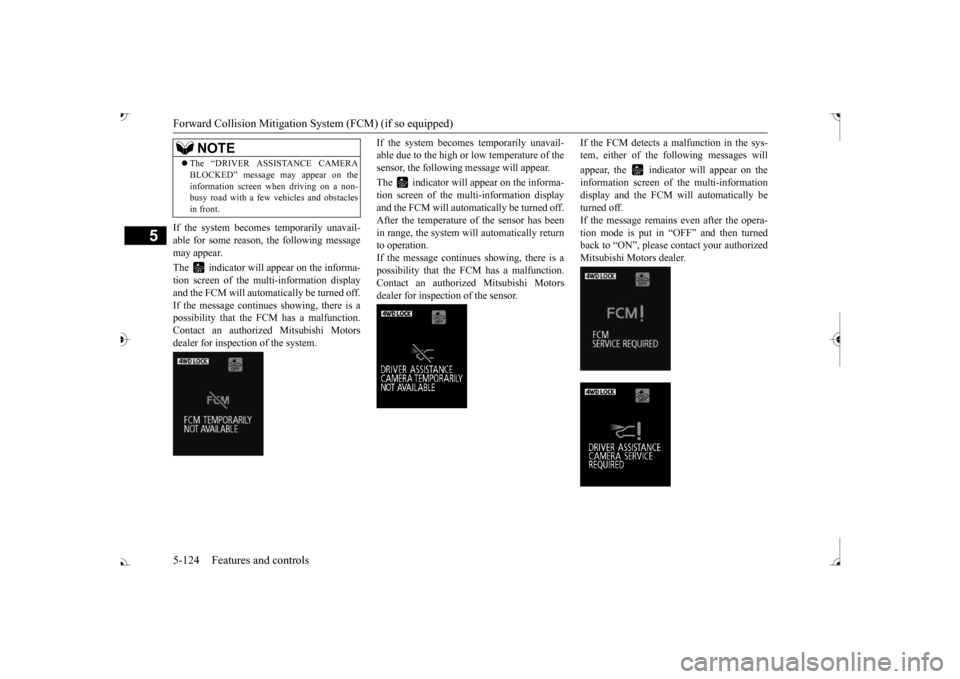
If the system becomes temporarily unavail- able for some reason, the following message may appear. The indicator will appear on the informa- tion screen of the mu
lti-information display
and the FCM will automa
tically be turned off.
If the message continues
showing, there is a
possibility that the FCM has a malfunction.Contact an authoriz
ed Mitsubishi Motors
dealer for inspection of the system.
If the system becomes temporarily unavail- able due to the high or low temperature of thesensor, the following
message will appear.
The indicator will appear on the informa- tion screen of the multi-information display and the FCM will automatically be turned off.After the temperature of
the sensor has been
in range, the system will automatically return to operation.If the message continues showing, there is a possibility that the
FCM has a malfunction.
Contact an authorized Mitsubishi Motors dealer for inspection of the sensor.
If the FCM detects a malfunction in the sys- tem, either of the following messages will appear, the indicator will appear on the information screen of the multi-information display and the FCM will automatically be turned off.If the message remains even after the opera- tion mode is put in “OFF” and then turned back to “ON”, please
contact your authorized
Mitsubishi Motors dealer.
The “DRIVER ASSI
STANCE CAMERA
BLOCKED” message
may appear on the
information screen when driving on a non-busy road with a few vehicles and obstacles in front.NOTE
BK0239700US.book 124 ページ 2016年6月16日 木曜日 午前10時58分
Page 214 of 521
Blind Spot Warning (BSW) (with Lane Change Assist) (if so equipped)
Features and controls 5-133
5
N00593500037
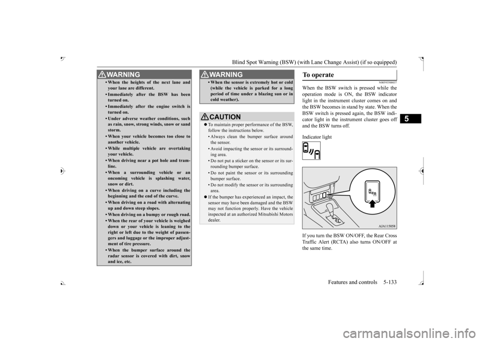
When the BSW switch is pressed while the operation mode is ON, the BSW indicator light in the instrument cluster comes on andthe BSW becomes in stand by state. When the BSW switch is pressed again, the BSW indi- cator light in the instrument cluster goes offand the BSW turns off. Indicator light If you turn the BSW ON/OFF, the Rear Cross Traffic Alert (RCTA) also turns ON/OFF atthe same time.
• When the heights of the next lane and your lane are different.• Immediately after the BSW has been turned on.• Immediately after the engine switch isturned on.• Under adverse weather conditions, suchas rain, snow, strong winds, snow or sand storm.• When your vehicle becomes too close toanother vehicle.• While multiple ve
hicle are overtaking
your vehicle.• When driving near a pot hole and tram-line.• When a surroundin
g vehicle or an
oncoming vehicle is splashing water,snow or dirt.• When driving on a
curve including the
beginning and the end of the curve.• When driving on a r
oad with alternating
up and down steep slopes.• When driving on a bumpy or rough road.• When the rear of your vehicle is weigheddown or your vehicle
is leaning to the
right or left due to the weight of passen- gers and luggage or th
e improper adjust-
ment of tire pressure. • When the bumper su
rface around the
radar sensor is covered with dirt, snowand ice, etc.WA R N I N G
• When the sensor is extremely hot or cold(while the vehicle is parked for a longperiod of time unde
r a blazing sun or in
cold weather).CAUTION To maintain proper performance of the BSW, follow the instructions below.• Always clean the bumper surface aroundthe sensor.• Avoid impacting the sensor or its surround-ing area.• Do not put a sticker on the sensor or its sur-rounding bumper surface.• Do not paint the sensor or its surroundingbumper surface.• Do not modify the sensor or its surroundingarea.
If the bumper has experienced an impact, the sensor may have been
damaged and the BSW
may not function properl
y. Have the vehicle
inspected at an authorized Mitsubishi Motorsdealer.WA R N I N G
To operate
BK0239700US.book 133 ページ 2016年6月16日 木曜日 午前10時58分
Page 215 of 521
Blind Spot Warning (BSW) (with Lane Change Assist) (if so equipped)
5
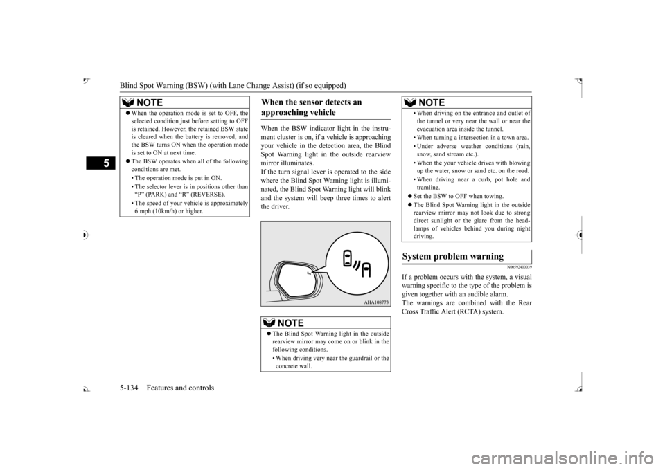
When the BSW indicator light in the instru- ment cluster is on, if
a vehicle is approaching
your vehicle in the detection area, the Blind Spot Warning light in
the outside rearview
mirror illuminates.If the turn signal lever is operated to the side where the Blind Spot Wa
rning light is illumi-
nated, the Blind Spot Wa
rning light will blink
and the system will beep three times to alert the driver.
N00592400039
If a problem occurs with the system, a visualwarning specific to the type of the problem isgiven together with an audible alarm. The warnings are combined with the Rear Cross Traffic Alert (RCTA) system.
NOTE
When the operation mode is set to OFF, the selected condition just before setting to OFFis retained. However, the retained BSW stateis cleared when the battery is removed, and the BSW turns ON when the operation mode is set to ON at next time. The BSW operates when all of the following conditions are met. • The operation mode
is put in ON.
• The selector lever is
in positions other than
Page 220 of 521
Lane Departure Warning System (LDW) (if so equipped)
Features and controls 5-139
5
N00577900059
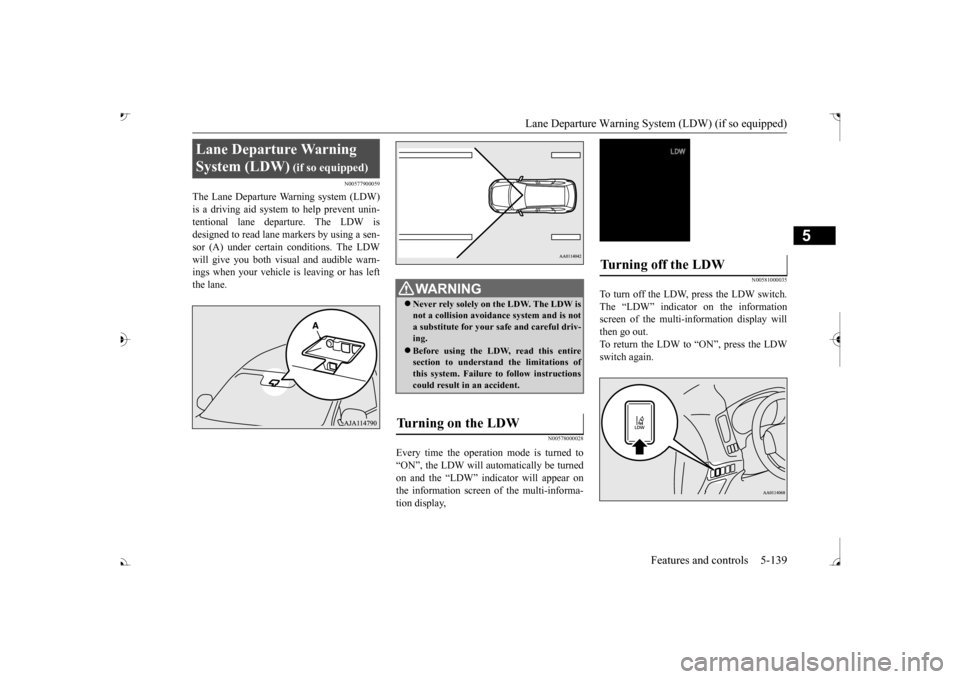
The Lane Departure Warning system (LDW) is a driving aid system to help prevent unin- tentional lane departure. The LDW isdesigned to read lane markers by using a sen- sor (A) under certain conditions. The LDW will give you both visual
and audible warn-
ings when your vehicle
is leaving or has left
the lane.
N00578000028
Every time the operation mode is turned to“ON”, the LDW will automatically be turned on and the “LDW” indica
tor will appear on
the information screen of the multi-informa- tion display,
N00581000035
To turn off the LDW, press the LDW switch. The “LDW” indicator on the informationscreen of the multi-in
formation display will
then go out. To return the LDW to “ON”, press the LDWswitch again.
Lane Departure Warning System (LDW)
WA R N I N G Never rely solely on the LDW. The LDW is not a collision avoidance system and is nota substitute for your safe and careful driv- ing. Before using the LDW, read this entire section to understand the limitations of this system. Failure to follow instructionscould result in an accident.
Turning on the LDW
Turning off the LDW
BK0239700US.book 139 ページ 2016年6月16日 木曜日 午前10時58分
Page 221 of 521
Lane Departure Warning System (LDW) (if so equipped) 5-140 Features and controls
5
N00581100036
The LDW, when turned ON, is capable of recognizing the lane in which your vehicle is travelling and issuing
an audible warning
when your vehicle begins to leave that travel lane. When operating, the “LDW” indicator on the multi-information display will be changed to indicator (green). The LDW
will not operate, however, and the “LDW”conditions have occurred: The vehicle speed is less than 38 mph (60 km/h). The turn signal lever
is being operated or
has been operated in the past 7 seconds. The hazard warning light is being oper- ated or has been operated in the past 7seconds.
N00581200040
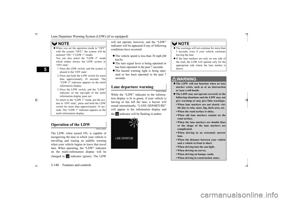
While the “LDW” indicator in the informa- tion display is lit in gr
een, if your vehicle is
leaving or has left the lane, a buzzer willsound intermittently, “LANE DEPARTURE” will appear in the information display and the indicator will be flashing in amber.
NOTE
When you set the operation mode to “OFF” with the system “OFF,” the system will berestored
Page 225 of 521
Tire pressure monitoring system 5-144 Features and controls
5
Each tire, including the spare (if provided), should be checked monthly when cold and inflated to the inflation pressure recom-mended by the vehicle manufacturer on the vehicle placard or tire
inflation pressure label.
(If your vehicle has tires of a different sizethan the size indicated on the vehicle placard or tire inflation pressure label, you should determine the proper ti
re inflation pressure
for those tires.) As an added safety feature, your vehicle has been equipped with a tire pressure monitoringsystem (TPMS) that illuminates a low tire pressure telltale when
one or more of your
tires is significant
ly under-inflated.
Accordingly, when the low tire pressure tell- tale illuminates, you should stop and check your tires as soon as possible, and inflatethem to the proper pressure. Driving on a sig- nificantly under-inflated
tire causes the tire to
overheat and can lead
to tire failure.
Under-inflation also reduces fuel efficiency and tire tread life, and may affect the vehi-cle’s handling and stoppi
ng ability. Please
note that the TPMS is
not a substitute for
proper tire maintenance,
and it is the driver’s
responsibility to
maintain corre
ct tire pres-
sure, even if under-inflation has not reached the level to trigger illumination of the TPMSlow tire pressure telltale. Your vehicle has also
been equipped with a
TPMS malfunction indica
tor to indicate when
the system is not operating properly. The TPMS malfunction indicator is combined with the low tire pressure telltale.When the system detects a malfunction, the telltale will flash for approximately one min- ute and then remain c
ontinuously illuminated.
This sequence will c
ontinue upon subsequent
vehicle start-ups as long as the malfunction exists.When the malfunction indicator is illumi- nated, the system may not
be able to detect or
signal low tire pr
essure as intended.
TPMS malfunctions may
occur for a variety
of reasons, including the installation of replacement or alternate tires or wheels on thevehicle that prevent the TPMS from function- ing properly. Always
check the TPMS mal-
function telltale after replacing one or moretires or wheels on your vehicle to ensure that the replacement or alternate tires and wheels
allow the TPMS to continue to function prop- erly.
N00532801511
1. If the tire pressure monitoring systemwarning light illuminates, avoiding hard braking, sharp steering maneuvers and high speeds. You should stop and adjust the tires to the proper inflation pressure as soon as possible. Adjust the spare tire atthe same time. Refer to “Tires” on page 9-15.
NOTE
In addition, the warni
ng display is displayed
on the information screen in the multi-infor-mation display.
If the warning light / display illuminates while driving
NOTE
In addition, the warni
ng display is displayed
on the information screen in the multi-infor- mation display. When inspecting or adjusting the tire pres- sure, do not apply excessive force to the valve stem to
avoid breakage.
After inspecting or adjusting the tire pres- sure, always reinstall the valve cap on thevalve stem. Without the valve cap, di
rt or moisture could
get into the valve, resulting in damage to thetire inflation pressure sensor. Do not use metal valve caps, which may cause a metal reaction,
resulting in corrosion
and damage of the tire
inflation pressure sen-
sors.
BK0239700US.book 144 ページ 2016年6月16日 木曜日 午前10時58分
Page 227 of 521
Tire pressure monitoring system 5-146 Features and controls
5
N00584300026
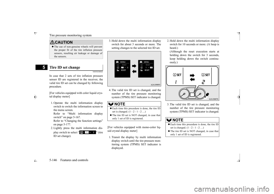
In case that 2 sets of tire inflation pressure sensor ID are registered in the receiver, the valid tire ID set can be changed by following procedure. [For vehicles equipped
with color liquid crys-
tal display meter] 1. Operate the multi information display switch to switch the information screen to the menu screen.Refer to “Multi in
formation display
switch” on page 5-167. Refer to “Changing the function settings”on page 5-177. 2. Lightly press the multi information dis- play switch to select “ ” (tire ID set change).
3. Hold down the multi information display switch for about 3 seconds or more. Thesetting changes to the selected tire ID set. 4. The valid tire ID se
t is changed, and the
number of the tire pressure monitoring system (TPMS) SET in
dicator is changed.
[For vehicles equipped
with mono-color liq-
uid crystal display meter] 1. Transit the display by multi information display switch until th
e tire pressure mon-
itoring system (TPMS) SET indicator isdisplayed.
2. Hold down the multi information display switch for 10 seconds or more. (A beep isheard.) (Although the reset execution starts at holding down the switch for 3 seconds,keep holding down the switch continu- ously.) 3. The valid tire ID set is changed, and the number of the tire
pressure monitoring
system (TPMS) SET i
ndicator is changed.
CAUTIONThe use of non-genuine wheels will prevent the proper fit of the tire inflation pressuresensors, resulting air
leakage or damage of
the sensors.
Tire ID set change
NOTE
Each time this procedure is done, the tire ID set is changed. (1 - 2 - 1 - 2 …) only 1 set of ID is registered.
NOTE
Each time this procedure is done, the tire ID set is changed. (1 - 2 - 1 - 2 …) only 1 set of ID is registered.
BK0239700US.book 146 ページ 2016年6月16日 木曜日 午前10時58分
Page 230 of 521
Parking sensors (Front/Rear) (if so equipped)
Features and controls 5-149
5
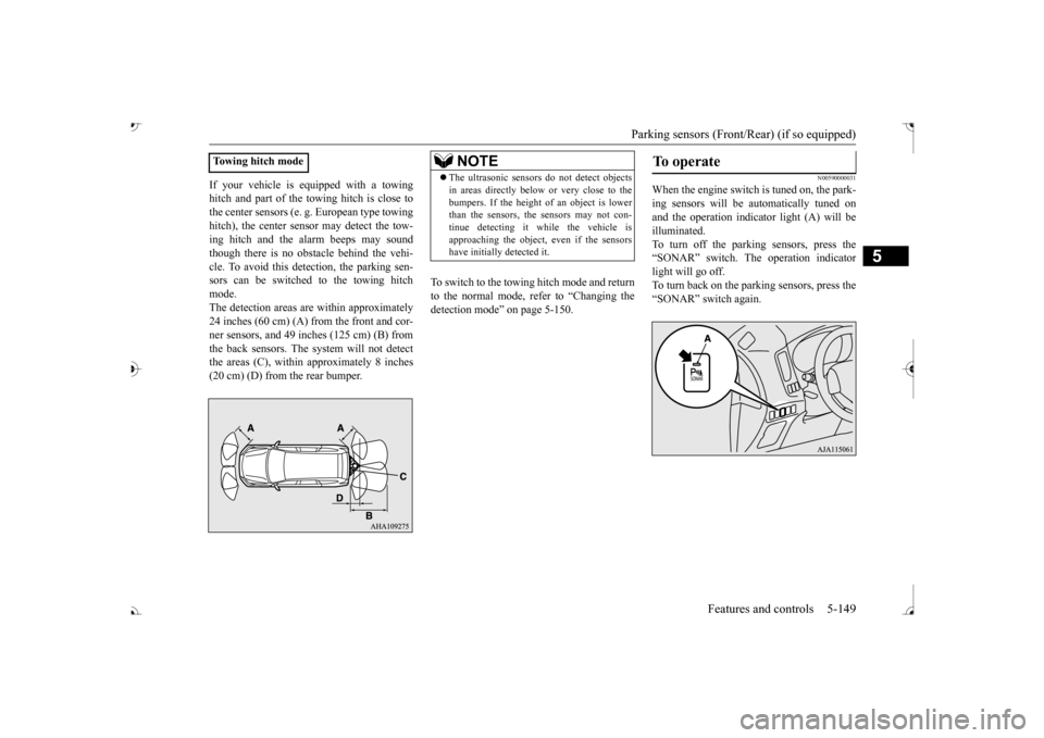
If your vehicle is equipped with a towing hitch and part of the towing hitch is close tothe center sensors (e. g.
European type towing
hitch), the center sens
or may detect the tow-
ing hitch and the alarm beeps may soundthough there is no obstacle behind the vehi- cle. To avoid this dete
ction, the parking sen-
sors can be switched to the towing hitchmode. The detection areas ar
e within approximately
24 inches (60 cm) (A) from the front and cor- ner sensors, and 49 inches (125 cm) (B) from the back sensors. The
system will not detect
the areas (C), within approximately 8 inches (20 cm) (D) from the rear bumper.
To switch to the towing hitch mode and return to the normal mode, refer to “Changing thedetection mode” on page 5-150.
N00590000031
When the engine switch is tuned on, the park- ing sensors will be
automatically tuned on
and the operation indica
tor light (A) will be
illuminated. To turn off the parking sensors, press the “SONAR” switch. The operation indicatorlight will go off. To turn back on the parking sensors, press the “SONAR” switch again.
Towing hitch mode
NOTE
The ultrasonic sensors
do not dete
ct objects
in areas directly below or very close to thebumpers. If the height of an object is lowerthan the sensors, the sensors may not con- tinue detecting it
while the vehicle is
approaching the object, even if the sensorshave initially detected it.
To operate
BK0239700US.book 149 ページ 2016年6月16日 木曜日 午前10時58分
Page 231 of 521
Parking sensors (Front/Rear) (if so equipped) 5-150 Features and controls
5
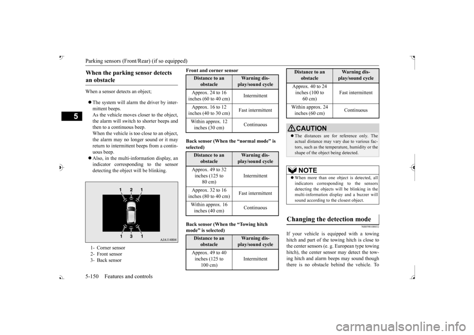
When a sensor detects an object; The system will alarm the driver by inter- mittent beeps.As the vehicle moves
closer to the object,
the alarm will switch to shorter beeps and then to a continuous beep.When the vehicle is too close to an object, the alarm may no longer sound or it may return to intermittent beeps from a contin- uous beep. Also, in the multi-information display, an indicator corresponding to the sensor detecting the objec
t will be blinking.
Front and corner sensor Back sensor (When the “normal mode” is selected) mode