remove seats MITSUBISHI OUTLANDER 2017 3.G Owners Manual
[x] Cancel search | Manufacturer: MITSUBISHI, Model Year: 2017, Model line: OUTLANDER, Model: MITSUBISHI OUTLANDER 2017 3.GPages: 521, PDF Size: 14.91 MB
Page 41 of 521
Head restraints 4-12 Seat and restraint systems
4
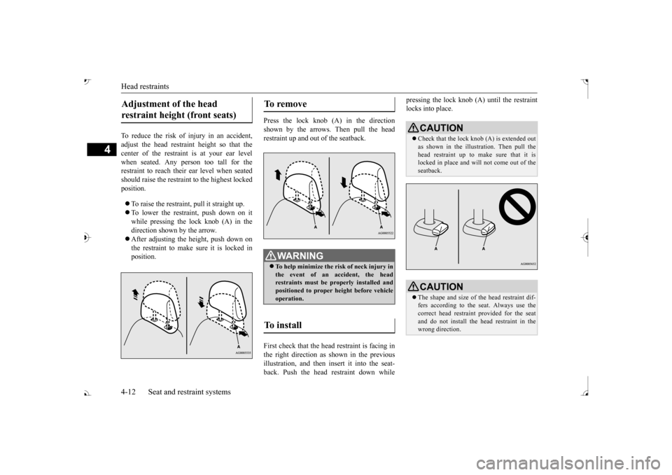
To reduce the risk of injury in an accident, adjust the head restraint height so that thecenter of the restrain
t is at your ear level
when seated. Any person too tall for the restraint to reach their ear level when seatedshould raise the restraint to the highest locked position. To raise the restraint, pull it straight up. To lower the restraint, push down on it while pressing the lock knob (A) in the direction shown by the arrow. After adjusting the height, push down on the restraint to make sure it is locked in position.
Press the lock knob (A) in the direction shown by the arrows. Then pull the head restraint up and out of the seatback. First check that the head restraint is facing in the right direction as shown in the previousillustration, and then insert it into the seat- back. Push the head restraint down while
pressing the lock knob (A) until the restraint locks into place.
Adjustment of the head restraint height (front seats)
To remove
WA R N I N G To help minimize the risk of neck injury in the event of an accident, the headrestraints must be properly installed and positioned to proper height before vehicle operation.
To install
CAUTION Check that the lock knob (A) is extended out as shown in the illustration. Then pull the head restraint up to make sure that it is locked in place and will
not come out of the
seatback.CAUTION The shape and size of the head restraint dif- fers according to the seat. Always use the correct head restraint provided for the seatand do not install the he
ad restraint in the
wrong direction.
BK0239700US.book 12 ページ 2016年6月16日 木曜日 午前10時58分
Page 45 of 521
Making a flat seat 4-16 Seat and restraint systems
4
N00409800021
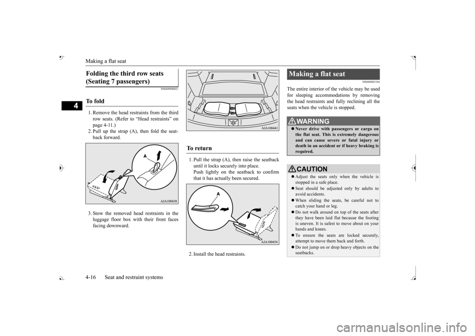
1. Remove the head restraints from the third row seats. (Refer to “Head restraints” on page 4-11.)2. Pull up the strap (A), then fold the seat- back forward. 3. Stow the removed head restraints in the luggage floor box with their front faces facing downward.
1. Pull the strap (A), then raise the seatback until it locks securely into place.Push lightly on the seatback to confirm that it has actually been secured. 2. Install the head restraints.
N00404801166
The entire interior of the vehicle may be used for sleeping accommoda
tions by removing
the head restraints and fully reclining all theseats when the vehicle is stopped.
Folding the third row seats (Seating 7 passengers) To f o l d
To r e t u r n
Making a flat seat
WA R N I N G Never drive with passengers or cargo on the flat seat. This is extremely dangerousand can cause severe or fatal injury or death in an accident
or if heavy braking is
required.CAUTION Adjust the seats only when the vehicle is stopped in a safe place. Seat should be adjusted only by adults to avoid accidents. When sliding the seat
s, be careful not to
catch your hand or leg. Do not walk around on top of the seats after they have been laid flat because the footingis uneven. It is safest to move about on your hands and knees. To ensure the seats are locked securely, attempt to move them back and forth. Do not jump on or drop heavy objects on the seatbacks.
BK0239700US.book 16 ページ 2016年6月16日 木曜日 午前10時58分
Page 46 of 521
Making a flat seat
Seat and restraint systems 4-17
4
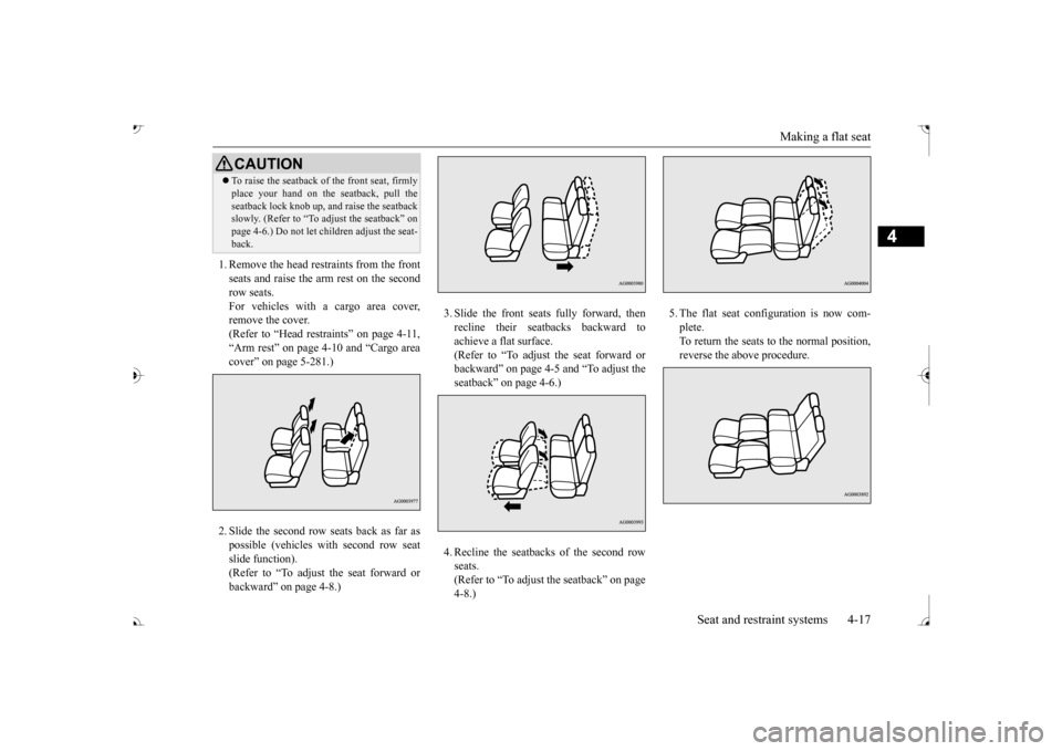
1. Remove the head restraints from the front seats and raise the arm rest on the secondrow seats. For vehicles with a cargo area cover, remove the cover.(Refer to “Head restraints” on page 4-11, “Arm rest” on page 4-10 and “Cargo area cover” on page 5-281.) 2. Slide the second row seats back as far as possible (vehicles with second row seat slide function).(Refer to “To adjust the seat forward or backward” on page 4-8.)
3. Slide the front seats fully forward, then recline their seatbacks backward toachieve a flat surface. (Refer to “To adjust the seat forward or backward” on page 4-5 and “To adjust theseatback” on page 4-6.) 4. Recline the seatbacks of the second row seats.(Refer to “To adjust the seatback” on page 4-8.)
plete.To return the seats to the normal position, reverse the above procedure.
To raise the seatback of the front seat, firmly place your hand on the
seatback, pull the
seatback lock knob up, and raise the seatbackslowly. (Refer to “To adjust the seatback” on page 4-6.) Do not let children adjust the seat- back.CAUTION
BK0239700US.book 17 ページ 2016年6月16日 木曜日 午前10時58分
Page 54 of 521
Seat belt use during pregnancy
Seat and restraint systems 4-25
4
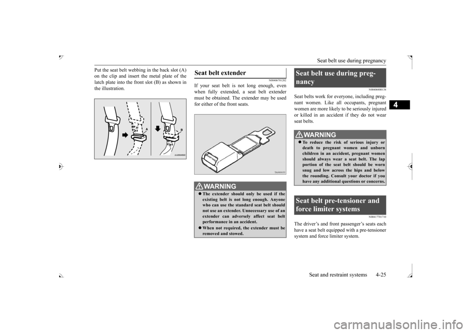
Put the seat belt webbing in the back slot (A) on the clip and insert the metal plate of thelatch plate into the front slot (B) as shown in the illustration.
N00406701202
If your seat belt is not long enough, evenwhen fully extended,
a seat belt extender
must be obtained. The extender may be usedfor either of the front seats.
N00406800134
Seat belts work for everyone, including preg- nant women. Like a
ll occupants, pregnant
women are more likely to be seriously injuredor killed in an accident if they do not wear seat belts.
N00417701710
The driver’s and front passenger’s seats each have a seat belt
equipped with a pre-tensioner
system and force limiter system.
Seat belt extender
WA R N I N G The extender should only be used if the existing belt is not long enough. Anyone who can use the standard seat belt shouldnot use an extender. Unnecessary use of an extender can adversel
y affect seat belt
performance in an accident. When not required, the extender must be removed and stowed.
Seat belt use during preg- nancy
WA R N I N G To reduce the risk of serious injury or death to pregnant women and unborn children in an accident, pregnant womenshould always wear
a seat belt. The lap
portion of the seat belt should be worn snug and low across the hips and belowthe rounding. Consult your doctor if you have any additional qu
estions or concerns.
Seat belt pre-tensioner and force limiter systems
BK0239700US.book 25 ページ 2016年6月16日 木曜日 午前10時58分
Page 59 of 521
Child restraint systems 4-30 Seat and restraint systems
4
N00418801167
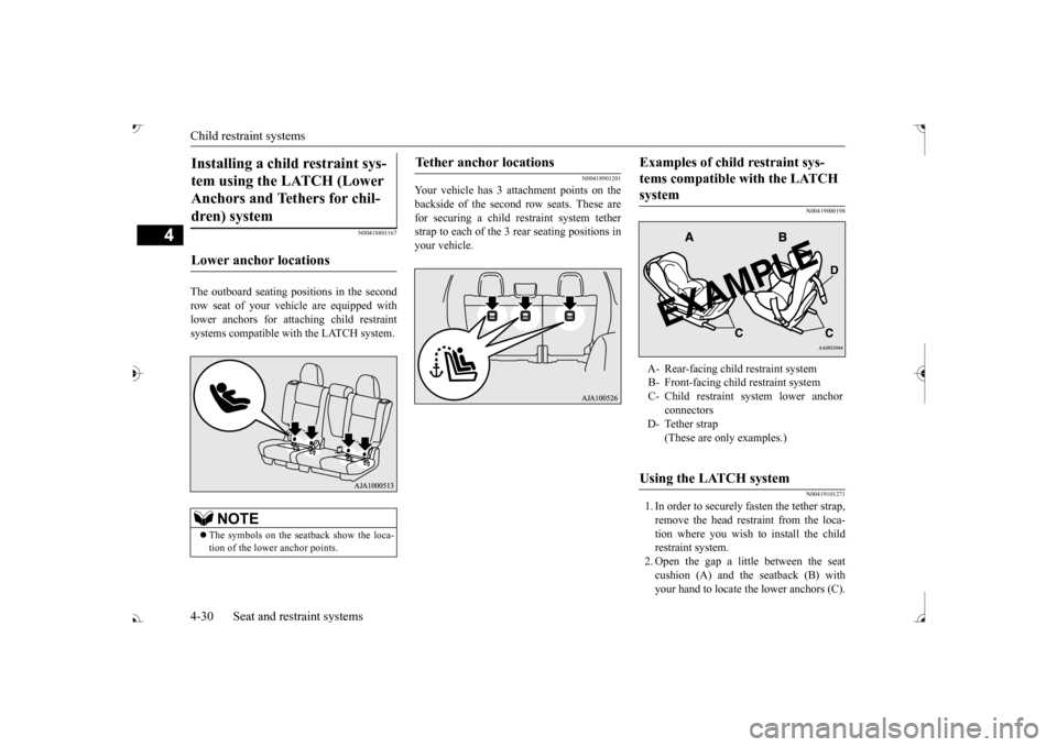
The outboard seating pos
itions in the second
row seat of your vehicle are equipped with lower anchors for attaching child restraint systems compatible with the LATCH system.
N00418901201
Your vehicle has 3 at
tachment points on the
backside of the second
row seats. These are
for securing a child restraint system tetherstrap to each of the 3 rear seating positions in your vehicle.
N00419000198 N00419101271
1. In order to securely
fasten the tether strap,
remove the head restraint from the loca- tion where you wish to install the child restraint system.2. Open the gap a little between the seat cushion (A) and the seatback (B) with your hand to locate the lower anchors (C).
Installing a child restraint sys- tem using the LATCH (Lower Anchors and Tethers for chil- dren) system Lower anchor locations
NOTE
The symbols on the seatback show the loca- tion of the lower anchor points.
Tether anchor locations
Examples of child restraint sys- tems compatible with the LATCH system A- Rear-facing child restraint system B- Front-facing child restraint system C- Child restraint system lower anchor
connectors
D- Tether strap
(These are only examples.)
Using the LATCH system
BK0239700US.book 30 ページ 2016年6月16日 木曜日 午前10時58分
Page 60 of 521
Child restraint systems
Seat and restraint systems 4-31
4
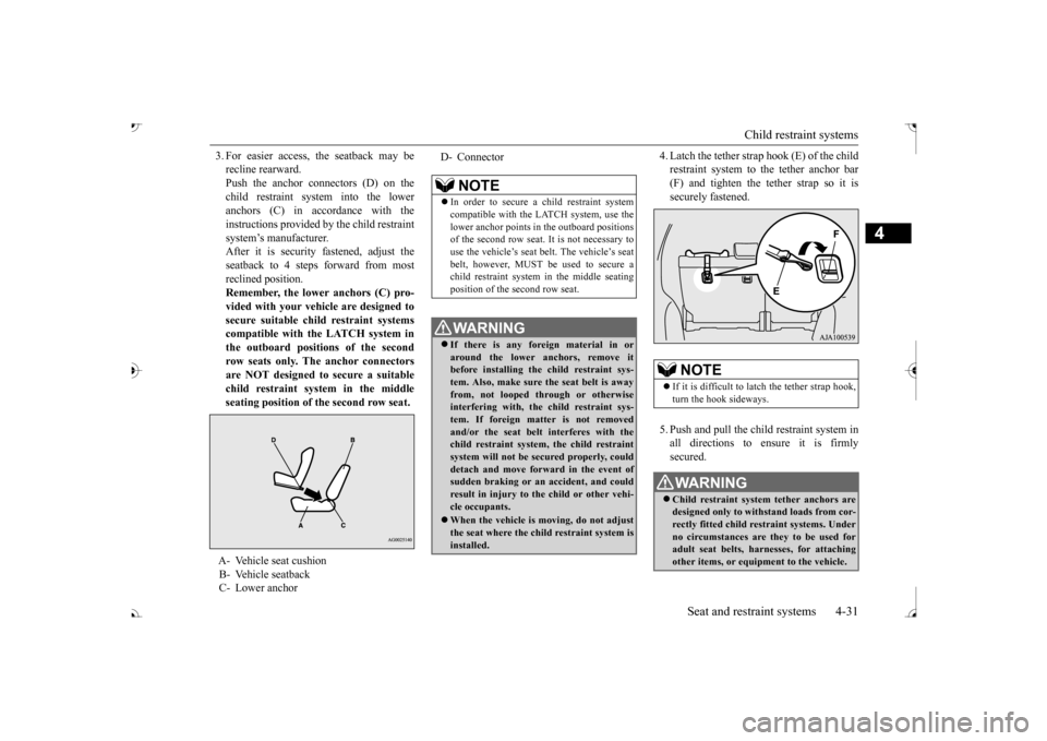
3. For easier access, the seatback may be recline rearward.Push the anchor connectors (D) on the child restraint system into the lower anchors (C) in accordance with theinstructions provided by the child restraint system’s manufacturer. After it is security fastened, adjust theseatback to 4 steps forward from most reclined position. Remember, the lower anchors (C) pro- vided with your vehi
cle are designed to
secure suitable child restraint systemscompatible with the LATCH system in the outboard positions of the second row seats only. The anchor connectorsare NOT designed to secure a suitable child restraint system in the middle seating position of the second row seat.
4. Latch the tether strap hook (E) of the child restraint system to the tether anchor bar(F) and tighten the tether strap so it is securely fastened. 5. Push and pull the chil
d restraint system in
all directions to ensure it is firmlysecured.
A- Vehicle seat cushion B- Vehicle seatback C- Lower anchor
D- Connector
NOTE
In order to secure a child restraint system compatible with the LATCH system, use thelower anchor points in the outboard positions of the second row seat. It is not necessary to use the vehicle’s seat
belt. The vehicle’s seat
belt, however, MUST be
used to secure a
child restraint system in the middle seating position of the second row seat.WA R N I N G If there is any foreign material in or around the lower an
chors, remove it
before installing the child restraint sys- tem. Also, make sure the seat belt is awayfrom, not looped through or otherwise interfering with, the child restraint sys- tem. If foreign matter is not removedand/or the seat belt
interferes with the
child restraint system, the child restraint system will not be secured properly, coulddetach and move forw
ard in the event of
sudden braking or an
accident, and could
result in injury to the child or other vehi-cle occupants. When the vehicle is
moving, do not adjust
the seat where the child restraint system isinstalled.
NOTE
If it is difficult to
latch the tether strap hook,
turn the hook sideways.WA R N I N G Child restraint system tether anchors are designed only to with
stand loads from cor-
rectly fitted child restraint systems. Underno circumstances are they to be used for adult seat belts, harnesses, for attaching other items, or equipment to the vehicle.
BK0239700US.book 31 ページ 2016年6月16日 木曜日 午前10時58分
Page 68 of 521
Supplemental Restraint System (SRS) - airbag
Seat and restraint systems 4-39
4
bag control unit controls deployment of the passenger’s front airbag in accordance withthe information it receives from this system. The passenger’s front ai
rbag will not deploy
in an impact when the system senses no occu-pant on the front passenger’s seat or a child in a child restraint system. In this case, the pas- senger airbag off indi
cator will come on.
Refer to “Passenger’s ai
rbag off indicator” on
page 4-39. If there is a problem involving the passen- ger’s seat occupant cl
assification sensor sys-
tem, the SRS warning light in the instrumentpanel will come on. Refer to “SRS warning light/display” on page 4-40.
N00418101346
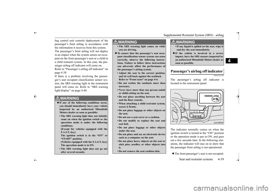
The passenger’s airbag off indicator is located in the instrument panel. The indicator normall
y comes on when the
ignition switch is turned to the “ON” position or the operation mode is put in ON, and goes out a few seconds later. In the following situ-ations, the indicator will stay on to show that the passenger front airb
ag is not operational.
The front passenger’s seat is not occupied.
WA R N I N GIf any of the following conditions occur, you should immediatel
y have your vehicle
inspected by an au
thorized Mitsubishi
Motors dealer as
soon as possible:
• The SRS warning light does not initially come on when the ignition switch or the operation mode is under the followingconditions. [Except for vehicles equipped with the F. A . S . T. - k e y ]The ignition switch is in the “ON” or “START” position. [Vehicles equipped with the F.A.S.T.-key]The operation mode is in ON.• The SRS warning light does not go outafter several seconds.
• The SRS warning li
ght comes on while
you are driving.
To ensure that the passenger’s seat occu- pant classification sensor system can sense correctly, observe the following instruc-tions. Failure to follow these instructions can adversely affect
the performance of
the passenger’s airbag system.• Adjust the seat to the correct position,and sit well back
against the seatback.
Refer to “Front seats” on page 4-4.• Do not recline the seatback more thannecessary.• Never have more than one person (adultor child) sitting
on the seat.
• Do not place anything between the seat and the floor console.• When attaching a chil
d restraint system,
secure it firmly.• Do not place luggage
or other objects on
the seat.• Do not use a seat cover or a cushion.• Do not modify or replace the seat andseat belt.• Do not place luggage or other objectsunder the seat.• Do not place and use
an electronic device
such as a computer on the seat.• Do not place heavy objects on the seat orstick pins, needles, or other objects intoit.• Do not remove the seat cushion skin.WA R N I N G
• If any liquid is spilled on the seat, wipe itand dry the seat
immediately.
If the vehicle is involved in a severe impact, have the SRS sensors inspected by an authorized
Mitsubishi Motors dealer as
soon as possible.
Passenger’s airbag off indicator
WA R N I N G
BK0239700US.book 39 ページ 2016年6月16日 木曜日 午前10時58分
Page 78 of 521
Supplemental Restraint System (SRS) - airbag
Seat and restraint systems 4-49
4
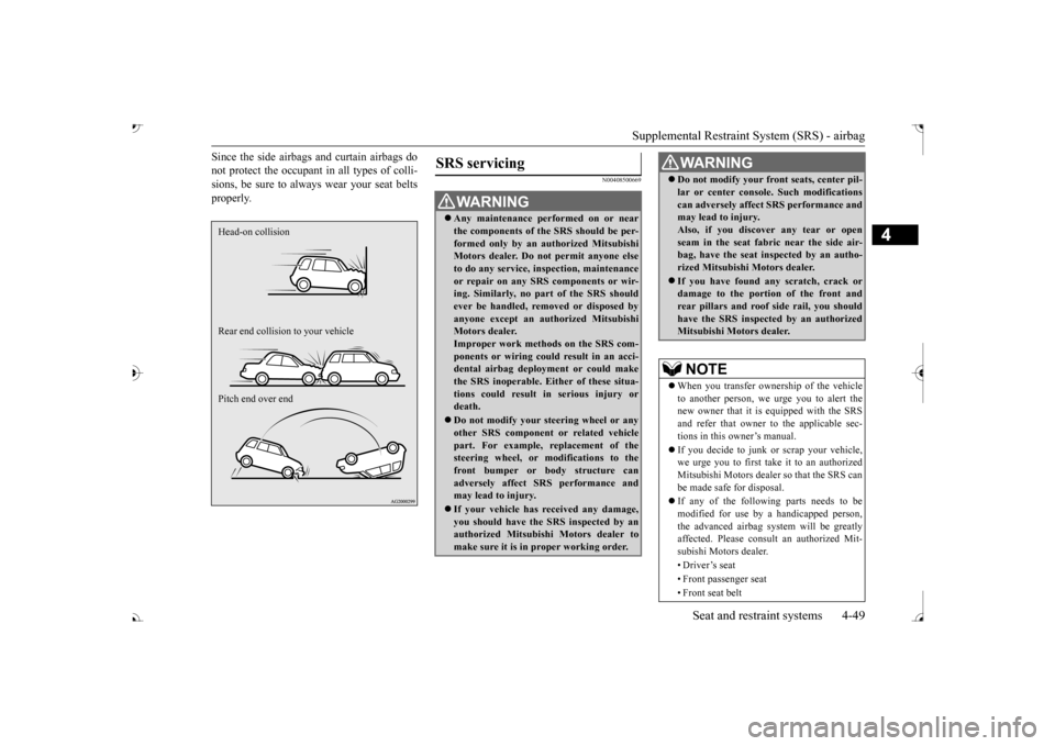
Since the side airbags and curtain airbags do not protect the occupant in all types of colli-sions, be sure to alwa
ys wear your seat belts
properly.
N00408500669
Head-on collision Rear end collision to your vehicle Pitch end over end
SRS servicing
WA R N I N G Any maintenance performed on or near the components of the SRS should be per-formed only by an
authorized Mitsubishi
Motors dealer. Do not permit anyone else to do any service, inspection, maintenanceor repair on any SRS components or wir- ing. Similarly, no part of the SRS should ever be handled, removed or disposed byanyone except an au
thorized Mitsubishi
Motors dealer. Improper work methods on the SRS com-ponents or wiring could result in an acci- dental airbag deployment or could make the SRS inoperable. Ei
ther of these situa-
tions could result in serious injury or death. Do not modify your steering wheel or any other SRS component
or related vehicle
part. For example, replacement of thesteering wheel, or modifications to the front bumper or body structure can adversely affect SR
S performance and
may lead to injury. If your vehicle has re
ceived any damage,
you should have the
SRS inspected by an
authorized Mitsubish
i Motors dealer to
make sure it is in proper working order.
Do not modify your fron
t seats, center pil-
lar or center console. Such modificationscan adversely affect
SRS performance and
may lead to injury. Also, if you discove
r any tear or open
seam in the seat fabr
ic near the side air-
bag, have the seat in
spected by an autho-
rized Mitsubishi Motors dealer. If you have found any scratch, crack or damage to the portion of the front and rear pillars and roof
side rail, you should
have the SRS inspecte
d by an authorized
Mitsubishi Motors dealer.NOTE
When you transfer ownership of the vehicle to another person, we urge you to alert the new owner that it is
equipped with the SRS
and refer that owner to the applicable sec- tions in this owner’s manual. If you decide to junk or scrap your vehicle, we urge you to first take it to an authorized Mitsubishi Motors dealer so that the SRS canbe made safe for disposal. If any of the following parts needs to be modified for use by
a handicapped person,
the advanced airbag sy
stem will be greatly
affected. Please consult an authorized Mit- subishi Motors dealer. •Driver’s seat • Front passenger seat • Front seat beltWA R N I N G
BK0239700US.book 49 ページ 2016年6月16日 木曜日 午前10時58分
Page 363 of 521
Cargo area cover (if so equipped) 5-282 Features and controls
5
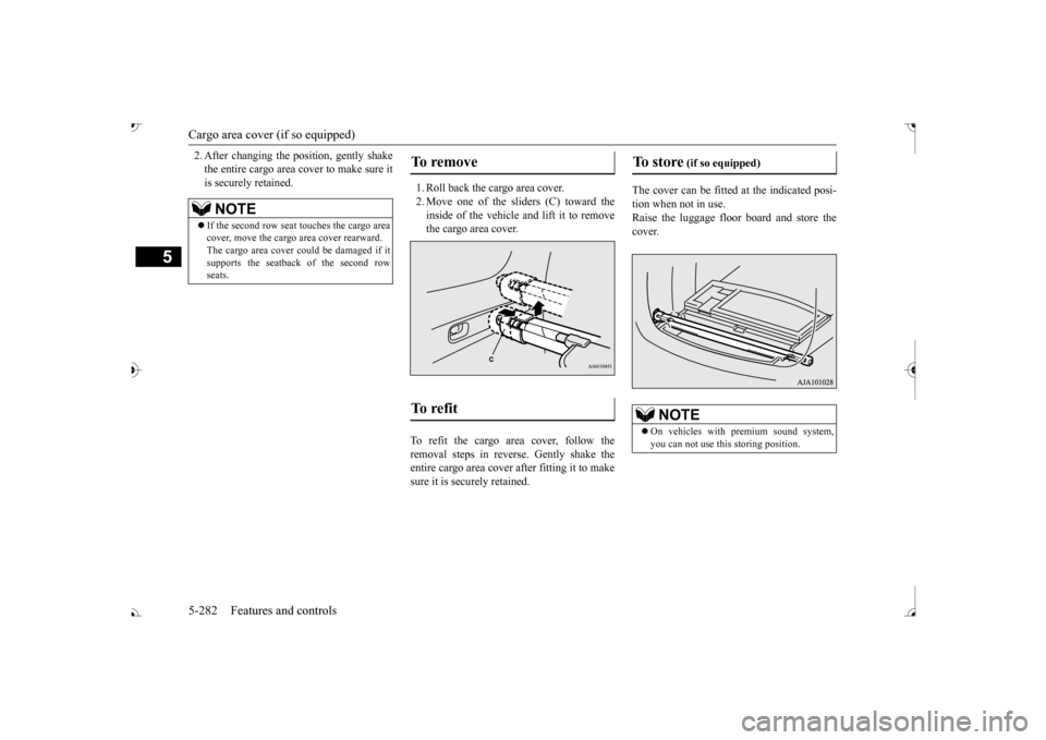
2. After changing the position, gently shake the entire cargo area cover to make sure itis securely retained.
1. Roll back the cargo area cover. 2. Move one of the sliders (C) toward the inside of the vehicle and lift it to remove the cargo area cover.
To refit the cargo area cover, follow the removal steps in reverse. Gently shake the entire cargo area cover
after fitting it to make
sure it is securely retained.
The cover can be fitted
at the indicated posi-
tion when not in use. Raise the luggage floor board and store thecover.
NOTE
If the second row seat
touches the cargo area
cover, move the cargo
area cover rearward.
The cargo area cover co
uld be damaged if it
supports the seatback of the second rowseats.
To remove To refit
To store
(if so equipped)
On vehicles with premium sound system, you can not use this storing position.
BK0239700US.book 282 ページ 2016年6月16日 木曜日 午前10時58分
Page 445 of 521
How to change a tire 8-10 For emergencies
8
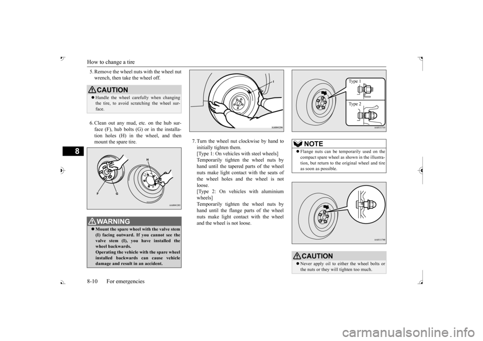
5. Remove the wheel nuts with the wheel nut wrench, then take the wheel off. 6. Clean out any mud, etc. on the hub sur- face (F), hub bolts (G)
or in the installa-
tion holes (H) in the wheel, and then mount the spare tire.
7. Turn the wheel nut clockwise by hand to initially tighten them. [Type 1: On vehicles
with steel wheels]
Temporarily tighten the wheel nuts by hand until the tapered parts of the wheel nuts make light contac
t with the seats of
the wheel holes and the wheel is not loose. [Type 2: On vehicles with aluminiumwheels] Temporarily tighten the wheel nuts by hand until the flange parts of the wheelnuts make light cont
act with the wheel
and the wheel is not loose.
CAUTION Handle the wheel carefully when changing the tire, to avoid scratching the wheel sur- face.WA R N I N G Mount the spare wheel with the valve stem (I) facing outward. If
you cannot see the
valve stem (I), you
have installed the
wheel backwards.Operating the vehicle with the spare wheel installed backwards can cause vehicle damage and result
in an ac
cident.
NOTE
Flange nuts can be te
mporarily used on the
compact spare wheel as shown in the illustra- tion, but return to the original wheel and tire as soon as possible.CAUTION Never apply oil to either the wheel bolts or the nuts or they will tighten too much.
Type 1 Type 2
BK0239700US.book 10 ページ 2016年6月16日 木曜日 午前10時58分