rear vent MITSUBISHI OUTLANDER 2020 (in English) User Guide
[x] Cancel search | Manufacturer: MITSUBISHI, Model Year: 2020, Model line: OUTLANDER, Model: MITSUBISHI OUTLANDER 2020Pages: 443, PDF Size: 60.03 MB
Page 58 of 443
Child restraint systems
Seat and restraint systems 4-29
4
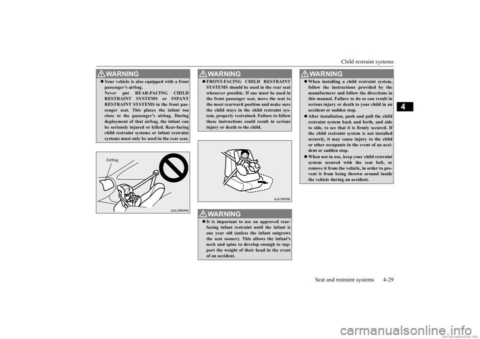
WA R N I N G Your vehicle is also
equipped with a front
passenger’s airbag.Never put REAR-FACING CHILDRESTRAINT SYSTEMS or INFANT RESTRAINT SYSTEMS in the front pas- senger seat. This pl
aces the infant too
close to the passenger’s airbag. During deployment of that airbag, the infant can be seriously injured or
killed. Rear-facing
child restraint systems or infant restraint systems must only be used in the rear seat.Airbag
WA R N I N G FRONT-FACING CHILD RESTRAINT SYSTEMS should be used in the rear seatwhenever possible. If one must be used inthe front passenger seat, move the seat to the most rearward po
sition and make sure
the child stays in the child restraint sys-tem, properly restrained. Failure to follow these instructions could result in serious injury or death to the child.WA R N I N G It is important to use an approved rear- facing infant restraint until the infant is one year old (unless
the infant outgrows
the seat sooner). This allows the infant’s neck and spine to de
velop enough to sup-
port the weight of their head in the eventof an accident.
When installing a child restraint system, follow the instructions provided by themanufacturer and follow the directions inthis manual. Failure to do so can result in serious injury or deat
h to your child in an
accident or
sudden stop.
After installation, push
and pull the child
restraint system back and forth, and sideto side, to see that it is firmly secured. If the child restraint system is not installed securely, it may cause injury to the childor other occupants in
the event of an acci-
dent or sudden stop. When not in use, keep your child restraint system secured with the seat belt, or remove it from the vehicle, in order to pre-vent it from being
thrown around inside
the vehicle during an accident.WA R N I N G
BK0278200US.book 29 ページ 2019年4月10日 水曜日 午前10時59分
Page 60 of 443
Child restraint systems
Seat and restraint systems 4-31
4
N00419000198 N00419101301
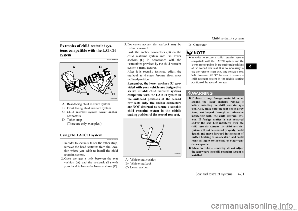
1. In order to securely fasten the tether strap, remove the head restraint from the loca- tion where you wish to install the child restraint system.2. Open the gap a little between the seat cushion (A) and the seatback (B) with your hand to locate the lower anchors (C).
3. For easier access, the seatback may be recline rearward.Push the anchor connectors (D) on the child restraint system into the lower anchors (C) in accordance with theinstructions provided by the child restraint system’s manufacturer. After it is security fastened, adjust theseatback to 4 steps forward from most reclined position. Remember, the lower anchors (C) pro- vided with your vehi
cle are designed to
secure suitable child restraint systemscompatible with the LATCH system in the outboard positions of the second row seats only. The anchor connectorsare NOT designed to secure a suitable child restraint system in the middle seating position of the second row seat.
Examples of child restraint sys- tems compatible with the LATCH system A- Rear-facing child
restraint system
B- Front-facing child restraint system C- Child restraint system lower anchor
connectors
D- Tether strap
(These are only examples.)
Using the LATCH system
A- Vehicle seat cushionB- Vehicle seatback C- Lower anchor
D- Connector
NOTE
In order to secure a child restraint system compatible with the LATCH system, use thelower anchor points in the outboard positions of the second row seat. It is not necessary to use the vehicle’s seat
belt. The vehicle’s seat
belt, however, MUST be
used to secure a
child restraint system in the middle seating position of the second row seat.WA R N I N G If there is any foreign material in or around the lower anchors, remove it before installing the child restraint sys- tem. Also, make sure the seat belt is awayfrom, not looped through or otherwise interfering with, the child restraint sys- tem. If foreign matter is not removedand/or the seat belt interferes with the child restraint system, the child restraint system will not be secured properly, coulddetach and move forward in the event of sudden braking or an
accident, and could
result in injury to the child or other vehi-cle occupants. When the vehicle is moving, do not adjust the seat where the child restraint system isinstalled.
BK0278200US.book 31 ページ 2019年4月10日 水曜日 午前10時59分
Page 77 of 443
Supplemental Restraint System (SRS) - airbag 4-48 Seat and restraint systems
4
N00408201591
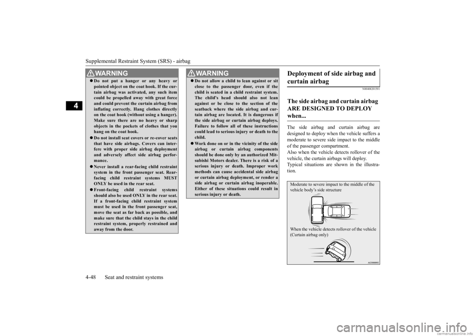
The side airbag and curtain airbag are designed to deploy when the vehicle suffers a moderate to seve
re side impact to the middle
of the passenger compartment.Also when the vehicle
detects rollover of the
vehicle, the curtain airbags will deploy. Typical situations are shown in the illustra-tion.
WA R N I N G Do not put a hanger or any heavy or pointed object on the coat hook. If the cur-tain airbag was activated, any such itemcould be propelled aw
ay with great force
and could prevent th
e curtain airbag from
inflating correctly. Hang clothes directlyon the coat hook (without using a hanger). Make sure there are no heavy or sharp objects in the pocket
s of clothes that you
hang on the coat hook. Do not install seat cove
rs or re-cover seats
that have side airbag
s. Covers can inter-
fere with proper si
de airbag deployment
and adversely affect
side airbag perfor-
mance. Never install a rear-facing child restraint system in the front passenger seat. Rear- facing child restraint systems MUST ONLY be used in the rear seat. Front-facing child restraint systems should also be used ON
LY in the rear seat.
If a front-facing child restraint system must be used in the front passenger seat, move the seat as far back as possible, andmake sure that the child stays in the child restraint system, properly restrained and away from the door.
Do not allow a child to lean against or sit close to the passenger door, even if thechild is seated in a child restraint system.The child’s head should also not lean against or be close to the section of the seatback where the side airbag and cur-tain airbag are located. It is dangerous if the side airbag or cu
rtain airbag deploys.
Failure to follow all of these instructionscould lead to serious in
jury or death to the
child. Work done on or in th
e vicinity of the side
airbag or curtain
airbag components
should be done only
by an authorized Mit-
subishi Motors dealer. There is a risk of a serious injury or death. Improper work methods can cause acci
dental side airbag
or curtain airbag depl
oyment, or render a
side airbag or curtai
n airbag inoperable.
Either of these situations could result inserious injury or death.WA R N I N G
Deployment of side airbag and curtain airbag The side airbag and curtain airbag ARE DESIGNED TO DEPLOY when... Moderate to severe impact to the middle of the vehicle body’s side structure When the vehicle detects rollover of the vehicle (Curtain airbag only)
BK0278200US.book 48 ページ 2019年4月10日 水曜日 午前10時59分
Page 112 of 443
Free-hand Advanced Securi
ty Transmitter (F.A.S.T.-key) (if so equipped)
Features and controls 5-31
5
7. Release in sequence the LOCK and UNLOCK buttons within 8 seconds ofpressing the LOCK button in step 6. The immobilizer display on the information screen in the multi-information displaywill blink. (Perform
the following step
within 20 seconds.) When registration of ID code is complete, the buzzer will s
ound 3 times and the
immobilizer display will come on for 30 seconds. If an error occurs, F.A.S.T.-key program-ming will be terminated and the buzzer will sound for 3 seconds. 8. If you wish to register another F.A.S.T.- key, repeat the proc
ess from step 1 after
the operation mode is put in OFF. 9. When all F.A.S.T.-keys are registered, remove the F.A.S.T.-key from the keyslot.
N00515501412
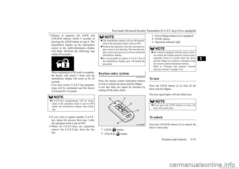
Press the remote control transmitter buttonsto lock or unlock the doors and the liftgate.It can also help you signal for attention by setting off the panic alarm.
Press the LOCK button (1) to lock all the doors and the liftgate. The turn signal lights
will also blink once.
Press the UNLOCK button (2) to unlock the driver’s door only.
NOTE
F.A.S.T.-key programming will be termi- nated if the operation mode is put in OFF before the immobilizer
display starts blink-
ing.
NOTE
The immobilizer displa
y will go off immedi-
ately if the operation
mode is put in OFF.
Perform the operation when the interrupt dis- play screen is not show
ing. The interrupt dis-
play screen may prevent you from seeing theimmobilizer display. It is not possible to register a F.A.S.T.-key if the immobilizer displa
y goes off during the
procedure.
Keyless entry system
1-
LOCK ( ) button
2-
UNLOCK ( ) button
3- Power liftgate button (if so equipped) 4- PANIC button 5- Operation indicator light
NOTE
On vehicles equipped wi
th the mirror retrac-
tor switch, the outside rearview mirrors auto- matically retract or extend when the doors and the liftgate are locked or unlocked usingthe remote control transmitter buttons. Refer to “Features and controls: Outside rearview mirrors” on page 5-63.
To l o c k
NOTE
If you press the LOCK button (1) twice, the horn will sound once.
To u n l o c k
BK0278200US.book 31 ページ 2019年4月10日 水曜日 午前10時59分
Page 121 of 443
Child safety locks for rear door 5-40 Features and controls
5
N00509401298
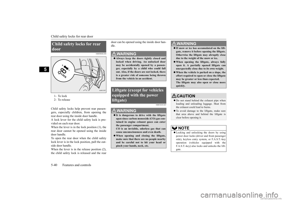
Child safety locks help prevent rear passen- gers, especially children, from opening therear door using the inside door handle. A lock lever for the child safety lock is pro- vided on each rear door.When the lever is in the lock position (1), the rear door cannot be opened using the inside door handle.To open the rear door when the child safety lock lever is in the lock position, pull the out- side door handle.When the lever is in the release position (2), the child safety lock is released and the rear
door can be opened using the inside door han- dle.
N00510101367
Child safety locks for rear door 1- To lock 2- To release
WA R N I N G Always keep the door
s tightly closed and
locked when driving. An unlocked door may be accidentally
opened by a passen-
ger, especially by
a child who could fall
out. Also, if the doors are not locked, there is a greater risk of
someone being thrown
from the vehicle in an accident.
Liftgate (except for vehicles equipped with the power liftgate)
WA R N I N G It is dangerous to drive with the liftgate open since carbon mo
noxide (CO) gas con-
tained in engine exhaust gases can enter the passenger compartment.CO is an invisible,
odorless gas that can
cause unconsciousness and even death. When opening and closing the liftgate, make sure that there are no people nearby and be careful not to hit your head or pinch your hands, neck, etc.
If snow or ice has ac
cumulated on the lift-
gate, remove it before
opening the liftgate.
Otherwise the liftgate may abruptly closedue to the weight of the snow or ice. When opening the lift
gate, always fully
open it. A partially opened liftgate can unexpectedly close due to its own weight. When the vehicle is parked on a slope, the effort required to open or close the liftgate may be greater or less than expected.The liftgate may also open or close more quickly.CAUTION Do not stand behind the exhaust pipe when loading and unloading
luggage. Heat from
the exhaust could lead to burns. To avoid damage to th
e liftgate, make sure
that area above and
behind the liftgate is
clear before opening it.NOTE
Locking and unlocking the doors by using power door locks (driver and front passenger side), keyless entry system, or F.A.S.T.-key operation (vehicles equipped with theF.A.S.T.-key) also locks and unlocks the lift- gate.WA R N I N G
BK0278200US.book 40 ページ 2019年4月10日 水曜日 午前10時59分
Page 122 of 443
Liftgate (except for
vehicles equipped w
ith the power liftgate)
Features and controls 5-41
5
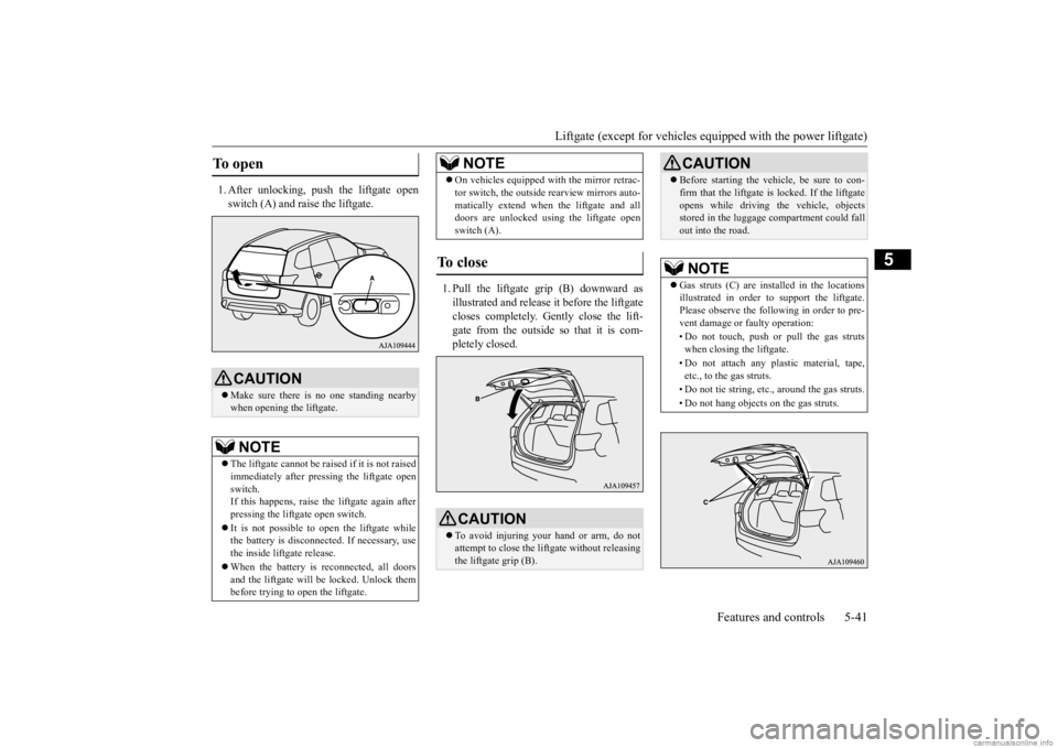
1. After unlocking, push the liftgate open switch (A) and raise the liftgate.
1. Pull the liftgate grip (B) downward as illustrated and release it before the liftgate closes completely. Gently close the lift- gate from the outside so that it is com-pletely closed.
To open
CAUTION Make sure there is no one standing nearby when opening the liftgate.NOTE
The liftgate cannot
be raised if it is not raised
immediately after pre
ssing the liftgate open
switch. If this happens, raise the liftgate again after pressing the liftgate open switch. It is not possible to open the liftgate while the battery is disconnected. If necessary, usethe inside liftgate release. When the battery is reconnected, all doors and the liftgate will be locked. Unlock them before trying to open the liftgate.
On vehicles e
quipped with the
mirror retrac-
tor switch, the outside rearview mirrors auto-matically extend when the liftgate and alldoors are unlocked using the liftgate open switch (A).
To close
CAUTION To avoid injuring your hand or arm, do not attempt to close the lift
gate without releasing
the liftgate grip (B).NOTE
Before starting the vehi
cle, be sure to con-
firm that the liftgate is locked. If the liftgateopens while driving the vehicle, objectsstored in the luggage compartment could fall out into the road.NOTE
Gas struts (C) are installed in the locations illustrated in order to
support the liftgate.
Please observe the following in order to pre-vent damage or faulty operation: • Do not touch, push or pull the gas struts when closing the liftgate. • Do not attach any pl
astic material, tape,
etc., to the gas struts. • Do not tie string, etc., around the gas struts.• Do not hang objects on the gas struts.CAUTION
BK0278200US.book 41 ページ 2019年4月10日 水曜日 午前10時59分
Page 131 of 443
Theft-alarm system 5-50 Features and controls
5
N00510401230
The alarm will be activated if any of the fol- lowing occur while the vehicle is parked andthe system is armed. One of the doors and the liftgate is opened without using the keyless entry system or the F.A.S.T.-key operation. The engine hood is opened.
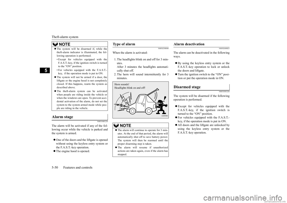
N00582500040
When the alarm is activated: 1. The headlights blink on and off for 3 min- utes. After 3 minutes the headlights automati-cally shut off. 2. The horn will sound intermittently for 3 minutes.
N00582600025
The alarm can be deactivated in the following ways. By using the keyless entry system or the F.A.S.T.-key operation to lock or unlockthe doors and liftgate. Turn the ignition switch to the “ON” posi- tion or put the operation mode in ON.
N00510501244
The system will be disarmed if the followingoperation is performed. Except for vehicles
equipped with the
F.A.S.T.-key, if the ignition switch is turned to the “ON” position. For vehicles equipped with the F.A.S.T.- key, if the operation mode is put in ON. All doors and the lift
gate are unlocked by
using the keyless entry system or the F.A.S.T.-key operation.
The system will be disarmed if, while the theft-alarm indicator is illuminated, the fol-lowing operation is performed. • Except for vehicles equipped with the F.A.S.T.-key, if the ignition switch is turnedto the “ON” position. • For vehicles equippe
d with the F.A.S.T.-
key, if the operation mode is put in ON.
The system will not be armed if a door, the liftgate or the engine
hood is not completely
closed. If this happens, rearm the system as described above. The theft-alarm system can be activated when people are riding inside the vehicle orwhen the windows are open. To prevent acci- dental activation of the alarm, do not set the system to the system armed mode while peo-ple are riding in the vehicle.
Alarm stage
NOTE
Type of alarm
NOTE
The alarm will continue to operate for 3 min- utes. At the end of that
period, the alarm will
automatically shut off
to save battery power.
The system will then
be rearmed until the
proper disarming step is taken. The alarm will resu
me if unauthorized
actions are taken again, even if the alarm has stopped.Horn sounds! Headlights blink on and off!
Alarm deactivation Disarmed stage
BK0278200US.book 50 ページ 2019年4月10日 水曜日 午前10時59分
Page 135 of 443
Sunroof (if so equipped) 5-54 Features and controls
5
N00551400014
Wind buffeting can be de
scribed as the per-
ception of pressure on the ears or a boomingor rumbling sound. Your
vehicle may exhibit
wind buffeting when driving with one or both rear door windows down or partially opened.This is a normal occurre
nce that can be mini-
mized. If the buffeting
occurs with the rear
door windows open, open the front door win-dows as well as the rear door windows to minimize the condition.
N00511001738
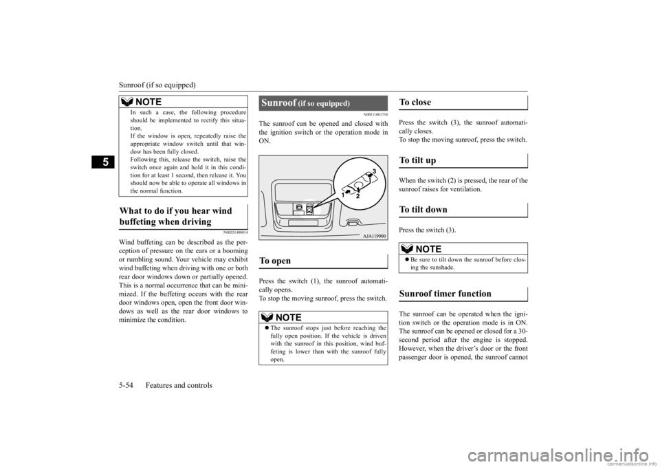
The sunroof can be opened and closed withthe ignition switch or the operation mode in ON. Press the switch (1), the sunroof automati- cally opens. To stop the moving sunroof, press the switch.
Press the switch (3), the sunroof automati- cally closes. To stop the moving sunroof, press the switch. When the switch (2) is pressed, the rear of the sunroof raises for ventilation. Press the switch (3). The sunroof can be operated when the igni- tion switch or the operation mode is in ON.The sunroof can be opened or closed for a 30- second period after th
e engine is stopped.
However, when the driver’s door or the frontpassenger door is opened, the sunroof cannot
In such a case, the
following procedure
should be implemented to rectify this situa-tion.If the window is open,
repeatedly raise the
appropriate wi
ndow switch until that win-
dow has been fully closed.Following this, release the switch, raise the switch once again and hold it in this condi- tion for at least 1 second, then release it. Youshould now be able to
operate all windows in
the normal function.
What to do if you hear wind buffeting when driving
NOTE
Sunroof
(if so equipped)
To open
NOTE
The sunroof stops just before reaching the fully open position. If the vehicle is drivenwith the sunroof in this position, wind buf- feting is lower than with the sunroof fully open.
To close
To t i l t u p
To t i l t d o w n
NOTE
Be sure to tilt down the sunroof before clos- ing the sunshade.
Sunroof timer function
BK0278200US.book 54 ページ 2019年4月10日 水曜日 午前10時59分
Page 141 of 443
Steering wheel height and reach adjustment 5-60 Features and controls
5
Warning light Warning display If there is a malfunction in the system, the warning light will come
on. In addition, the
warning display appears on the information screen in the multi information display.
Under normal conditions
, the warning light
only comes on when the operation mode isput in ON and goes off a few seconds later.
N00511501241
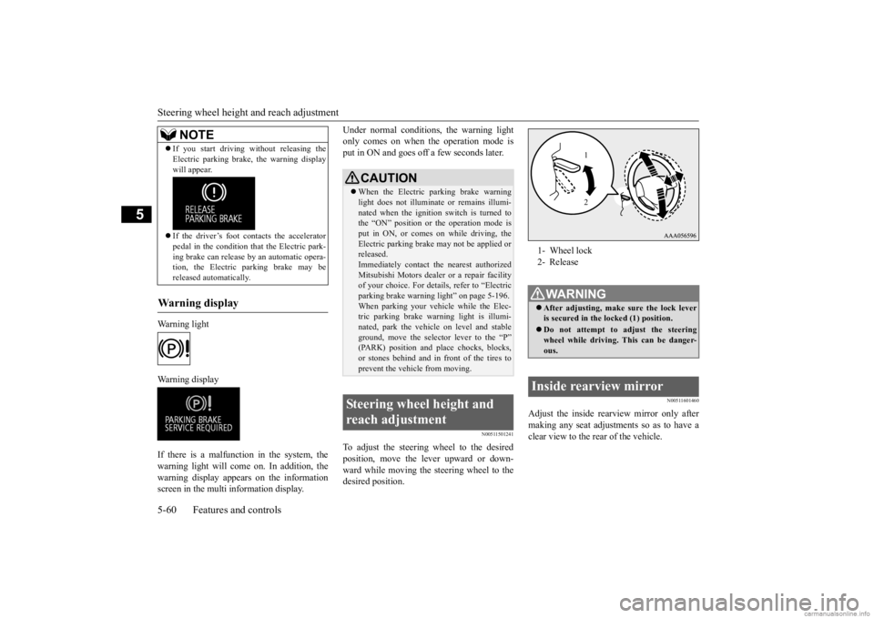
To adjust the steering wheel to the desiredposition, move the lever upward or down- ward while moving the steering wheel to the desired position.
N00511601460
Adjust the inside rearview mirror only after making any seat adjustme
nts so as to have a
clear view to the rear of the vehicle.
If you start driving without releasing the Electric parking brake,
the warning display
will appear. If the driver’s foot contacts the accelerator pedal in the condition th
at the Electric park-
ing brake can release
by an automatic opera-
tion, the Electric parking brake may be released automatically.
Warning display
NOTE
CAUTION When the Electric parking brake warning light does not i
lluminate or remains illumi-
nated when the ignition switch is turned to the “ON” position or
the operation mode is
put in ON, or comes on while driving, theElectric parking brake
may not be applied or
released. Immediately contact the nearest authorizedMitsubishi Motors dealer
or a repair facility
of your choice. For details, refer to “Electric parking brake warni
ng light” on page 5-196.
When parking your vehi
cle while
the Elec-
tric parking brake warning light is illumi- nated, park the vehicl
e on level and stable
ground, move the select
or lever to the “P”
(PARK) position and pl
ace chocks, blocks,
or stones behind and in front of the tires toprevent the vehicle from moving.
Steering wheel height and reach adjustment
1- Wheel lock 2- ReleaseWA R N I N G After adjusting, make
sure the lock lever
is secured in the locked (1) position. Do not attempt to adjust the steering wheel while driving. This can be danger-ous.
Inside rearview mirror
1 2
BK0278200US.book 60 ページ 2019年4月10日 水曜日 午前10時59分
Page 145 of 443

Outside rearview mirrors 5-64 Features and controls
5
N00549201256
The outside mirror can be retracted towards the side window to prevent damage when parking in tight locations. Push the mirror towards the back of the vehi- cle with your hand to retract it in. When extending the mirror, pull it out towards thefront of the vehicle until it clicks to lock in place.
With the ignition switch in the “ON” or “ACC” position or the operation mode in ON or ACC, push the mirror retractor switch to retract the mirrors. Push it again to extend the mirrors to their original positions. After placing the ignition switch in the“LOCK” position or the operation mode in OFF, it is possible to retract and extend the mirrors using the mirror retractor switch forapproximately 30 seconds.
4- Left
NOTE
After adjusting, return the lever to the “•”(OFF) position.
To retract the mirror Except for vehicles equipped with the mirror retractor switch
For vehicles equipped with the mirror retractor switchRetracting and extending the mir- rors using the mirror retractor switch
CAUTION It is possible to retract and extend the mirrors by hand. After retracti
ng a mirror using the
mirror retractor switch, however, you shouldextend it by using the switch again, not by hand. If you extended the mirror by hand after retracting it usi
ng the switch, it would
not properly lock in position. As a result, the mirror could move be
cause of the wind or
vibration while you are driving, and this mayprevent the driver’s rearward visibility.NOTE
Be careful not to get your hands trapped while a mirror is moving. If you move a mirror by hand or it moves after hitting a person or object, you may not be able to return it to its original positionusing the mirror retractor switch. If this hap- pens, push the mirror retractor switch to place the mirror in its retracted position andthen push the switch again to return the mir- ror to its original position. When freezing has occu
rred and mirrors fail
to operate as intended, please refrain from repeated pushing of the retractor switch asthis action can result
in burn-out of the mir-
ror motor circuits.
BK0278200US.book 64 ページ 2019年4月10日 水曜日 午前10時59分