instrument cluster MITSUBISHI OUTLANDER 2020 Owner's Manual (in English)
[x] Cancel search | Manufacturer: MITSUBISHI, Model Year: 2020, Model line: OUTLANDER, Model: MITSUBISHI OUTLANDER 2020Pages: 443, PDF Size: 60.03 MB
Page 5 of 443
Instruments and controls 1-1
1
Overview
N00100202919
Instruments and controls
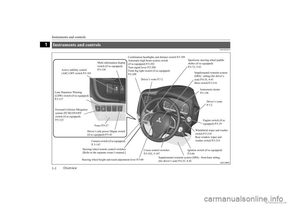
Combination headlights an
d dimmer switch P.5-199
Automatic high beam system switch (if so equipped) P.5-203 Turn signal lever P.5-208 Front fog light switc
h (if so equipped)
P.5-209
Steering wheel remote control switches [Refer to the separate owner’s manual.]
Active stability control (ASC) OFF switch P.5-101
Supplemental restraint system (SRS) - airbag (for driver’s seat) P.4-35, 4-41 Horn switch P.5-218
Instrument cluster P.5-156
Windshield wiper and washer switch P.5-210 Rear window wiper and washer switch P.5-214
Cruise control switches P.5-103, 5-107
Steering wheel height and reach adjustment lever P.5-60
Engine switch (if so equipped) P.5-19
Driver’s vents P. 7 - 2
Sportronic steering wheel paddle shifter (if so equipped) P.5-73, 5-81
Driver’s vents P.7-2
Multi information display switch (if so equipped) P.5-158
Driver’s side power liftgate switch (if so equipped) P.5-43
Fuses P.9-27
Lane Departure Warning (LDW) switch (if so equipped) P.5-137 Forward Collision Mitigation system (FCM) ON/OFF switch (if so equipped)P.5-123
Supplemental restraint system (SRS) - front knee airbag (for driver’s seat) P.4-35, 4-42
Ignition switch (if so equipped) P.5-66
Camera switch (if so equipped) P. 5-147
BK0278200US.book 1 ページ 2019年4月10日 水曜日 午前10時59分
Page 82 of 443
5
Features and controlsBreak-in recommendations ..............................................................5-3 Keys .................................................................................................5-3 Electronic immobilizer (Anti-theft starting system) ........................5-4Keyless entry system (if so equipped) ..............................................5-7 Free-hand Advanced Security
Transmitter (F.A.S.T.-key)
(if so equipped) ..........................................................................5-15Door locks ......................................................................................5-36 Power door locks ......
...........
...........
...........
...........
...........
.........
.....5-38
Child safety locks for rear door ..........
...........
.........
.........
.........
.....5-40
Liftgate (except for vehi
cles equipped with the
power liftgate) ....5-40
Power liftgate (if so equipped) .......................................................5-42 Inside liftgate release .....................................................................5-48Theft-alarm system ........................................................................5-49 Power window control ...................................................................5-51 Sunroof (if so equipped) .................................................................5-54Parking brake .................................................................................5-56 Steering wheel height and reach adjustment ..................................5-60 Inside rearview mirror ...................................................................5-60Outside rearview mirrors ...............................................................5-63 Ignition switch (if so equipped) ......................................................5-66 Steering wheel lock (if so equipped) ..............................................5-68Starting the engine .........................................................................5-68 Automatic transaxle (if so equipped)..............................................5-70 Continuously variable transmission
(CVT) (if so equipped)..........5-76
Electronically controlled
4WD system (if so equipped).................5-83
S-AWC (Super-All Wheel Control) (if
so equipped) .....................5-85
4-wheel drive operation .................................................................5-88Inspection and maintenance followi
ng rough road operation ........5-91
Cautions on the handling of 4-wheel dr
ive vehicles ..................... 5-91
Service brake ................................................................................. 5-92 Brake auto hold (if so equipped) .................................................... 5-93Hill start assist (if so equipped) ...................................................... 5-96 Brake assist system ........................................................................ 5-97 Anti-lock braking system .............................................................. 5-97Electric power steering system (EPS) ........................................... 5-99 Active stability control (ASC) ..................................................... 5-100 Cruise control (if so equipped) ..................................................... 5-103Adaptive Cruise Control System (ACC)
(if so equipped) ............ 5-107
Forward Collision Mitigation System
(FCM) (if so equipped) .... 5-118
Blind Spot Warning (BSW) (w
ith Lane Change Assist)
(if so equipped) ........................................................................ 5-127 Rear Cross Traffic Alert (RCTA) (if so equipped) ....................... 5-133 Lane Departure Warning System (LDW
) (if so equipped)........... 5-137
Tire pressure monitoring system ................................................. 5-140 Rear-view camera (if so equipped)............................................... 5-145 Multi Around Monitor (if so
equipped)..................
...........
........... 5-147
Instrument cluster ........................................................................ 5-156 Multi Information display ............................................................ 5-157 Indicator light, warning light, and information screen display list ..................................................................... 5-176 Indicators ..................................................................................... 5-195 Warning lights .............................................................................. 5-196Information screen display .......................................................... 5-198 Combination headlights and dimmer switch ............................... 5-199 Turn signal lever .......................................................................... 5-208Hazard warning flasher switch .................................................... 5-209
BK0278200US.book 1 ページ 2019年4月10日 水曜日 午前10時59分
Page 139 of 443
Parking brake 5-58 Features and controls
5
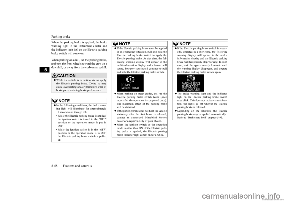
When the parking brake is applied, the brake warning light in the instrument cluster andthe indicator light (A) on the Electric parking brake switch will come on. When parking on a hill, set the parking brake, and turn the front wheels toward the curb on adownhill, or away from
the curb on an uphill.
CAUTIONWhile the vehicle is in
motion, do not apply
the Electric parking
brake. Doing so may
cause overheating and/or
premature wear of
brake parts, reducing brake performance. NOTE
In the following condi
tions, the brake warn-
ing light will illuminate for approximately15 seconds and then go off. • While the Electric pa
rking brake is applied,
the ignition switch is turned to the “OFF” position or the opera
tion mode is put in
OFF. • While the ignition switch is in the “OFF” position or the operation mode is in OFF,the Electric pa
rking brake switch is pulled
up.
If the Electric parking
brake must be applied
in an emergency situation, pull and hold theElectric parking brake
switch to apply the
Electric parking brake. At that time, the fol- lowing warning display will appear in the multi-information disp
lay and a buzzer will
sound, however you shoul
d continue to pull
and hold the Electric
parking brake switch.
When parking on steep grades, pull up the Electric parking brak
e switch twice (once
more after the operati
on is completed once).
The maximum effect of the parking brakewill be obtained. If the parking brake does not hold the vehicle stationary after the foot brake is released, contact an authorized Mitsubishi Motors dealer or a repair facility of your choice. When the ignition switch or the operation mode is other than ON, if the Electric park-ing brake is applied, the Electric parking brake indicator light comes on for a while.NOTE
If the Electric parking brake switch is repeat- edly operated in a short time, the followingwarning display will
appear in the multi-
information display and
the Electric parking
brake will temporarily
stop working. In such
case, wait for approxi
mately 1 minute until
the warning display di
sappears, and operate
the Electric parki
ng brake switch again.
The brake warning light
and the indicator
light on the Electric
parking brake switch
may blink. This does not
indicate a malfunc-
tion, the lights go off when/if the Electricparking brake is released. Depending on the situat
ion, the Electric
parking brake may be
applied automatically.
Refer to “Brake auto hold” on page 5-93.NOTE
BK0278200US.book 58 ページ 2019年4月10日 水曜日 午前10時59分
Page 175 of 443
Brake auto hold (if so equipped) 5-94 Features and controls
5
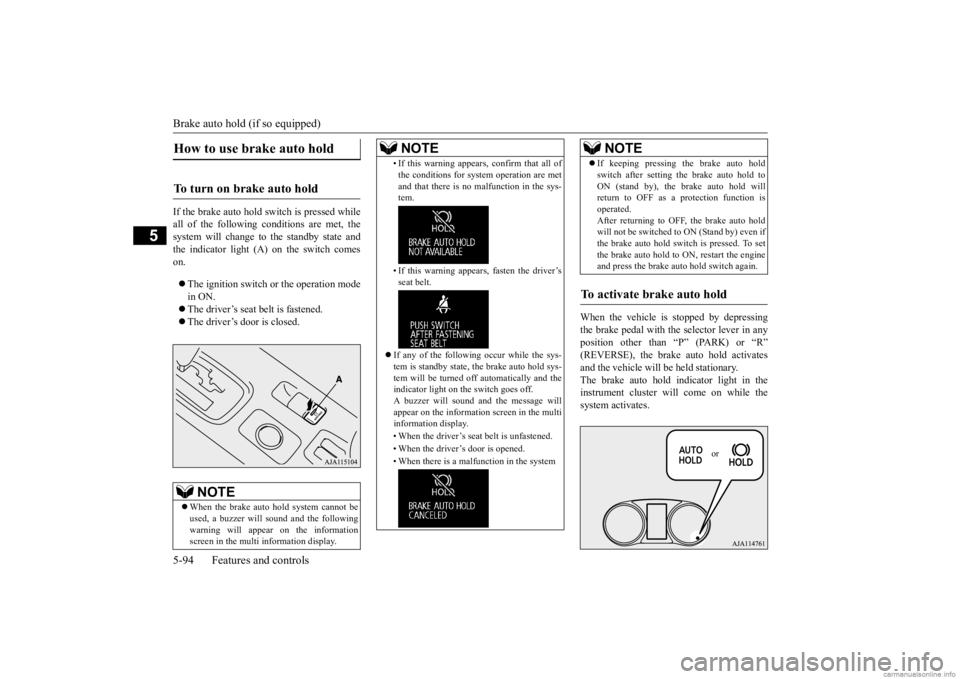
If the brake auto hold switch is pressed while all of the following conditions are met, the system will change to the standby state and the indicator light (A) on the switch comeson. The ignition switch or
the operation mode
in ON. The driver’s seat belt is fastened. The driver’s door is closed.
When the vehicle is
stopped by depressing
the brake pedal with the selector lever in any position other than “P” (PARK) or “R”(REVERSE), the brake auto hold activates and the vehicle will be
held stationary.
The brake auto hold indicator light in theinstrument cluster will come on while the system activates.
How to use brake auto hold
To turn on brake auto hold
NOTE
When the brake auto hold system cannot be used, a buzzer will sound and the following warning will appear on the information screen in the multi information display.
• If this warning appear
s, confirm that all of
the conditions for system operation are metand that there is no malfunction in the sys-tem. • If this warning appear
s, fasten the driver’s
seat belt.
If any of the following occur while the sys- tem is standby state, the brake auto hold sys-tem will be turned off automatically and the indicator light on the switch goes off. A buzzer will sound a
nd the message will
appear on the information screen in the multi information display. • When the driver’s seat
belt is unfastened.
• When the driver’s door is opened.• When there is a malfunction in the systemNOTE
If keeping pressing the brake auto hold switch after setting
the brake auto hold to
ON (stand by), the brake auto hold willreturn to OFF as a protection function is operated. After returning to OFF, the brake auto holdwill not be switched to
ON (Stand by) even if
the brake auto hold switch is pressed. To set the brake auto hold to
ON, restart the engine
and press the brake auto hold switch again.
To activate brake auto hold
NOTE
or
BK0278200US.book 94 ページ 2019年4月10日 水曜日 午前10時59分
Page 176 of 443
Brake auto hold (if so equipped)
Features and controls 5-95
5
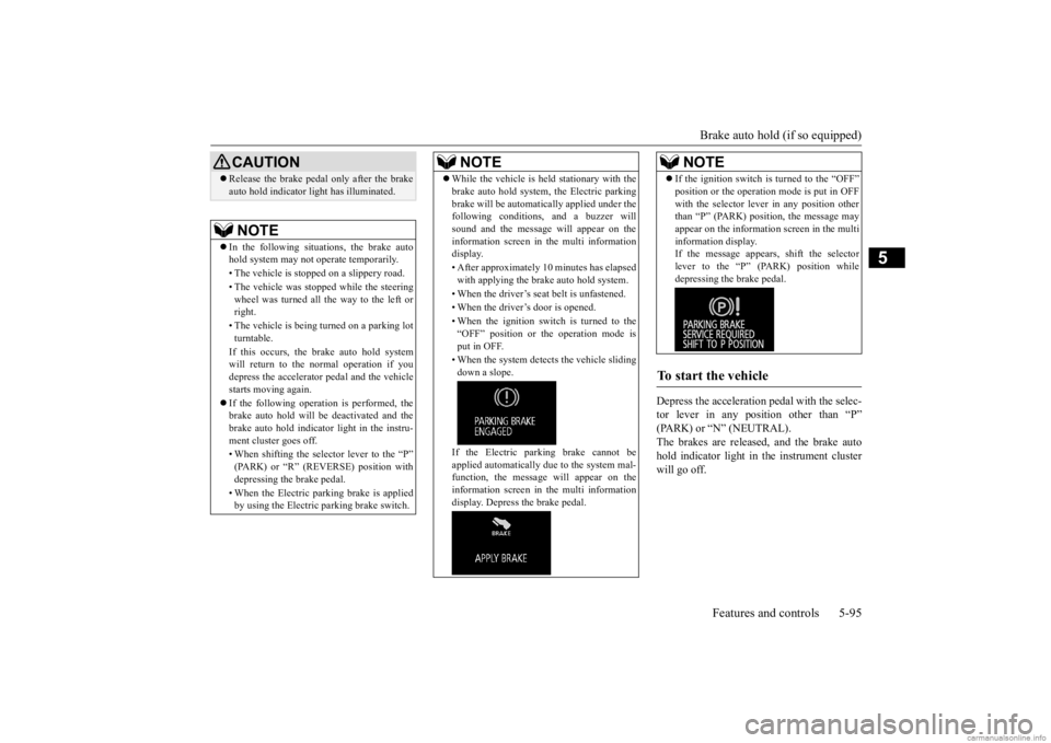
Depress the acceleration
pedal with the selec-
tor lever in any position other than “P” (PARK) or “N” (NEUTRAL). The brakes are released, and the brake autohold indicator light in
the instrument cluster
will go off.
CAUTION Release the brake pedal only after the brake auto hold indicator li
ght has illuminated.
NOTE
In the following situations, the brake auto hold system may not
operate temporarily.
• The vehicle is stoppe
d on a slippery road.
• The vehicle was stoppe
d while the steering
wheel was turned all the way to the left or right. • The vehicle is being turned on a parking lot turntable. If this occurs, the brake auto hold system will return to the normal operation if youdepress the accelerator
pedal and the vehicle
starts moving again. If the following operation is performed, the brake auto hold will be
deactivated and the
brake auto hold indicator light in the instru-ment cluster goes off. • When shifting the selector lever to the “P” (PARK) or “R” (REVERSE) position with depressing the brake pedal. • When the Electric park
ing brake is applied
by using the Electric
parking brake switch.
While the vehicle is held stationary with the brake auto hold system, the Electric parkingbrake will be automati
cally applied under the
following conditions, and a buzzer will sound and the message will appear on the information screen in the multi informationdisplay. • After approximately 10 minutes has elapsed with applying the brake auto hold system. • When the driver’s seat
belt is unfastened.
• When the driver’s door is opened. • When the ignition switch is turned to the “OFF” position or th
e operation mode is
put in OFF. • When the system detect
s the vehicle sliding
down a slope. If the Electric park
ing brake cannot be
applied automatically due to the system mal- function, the message
will appear on the
information screen in the multi informationdisplay. Depress the brake pedal.NOTE
If the ignition switch is turned to the “OFF” position or the operation mode is put in OFFwith the selector leve
r in any position other
than “P” (PARK) position, the message may appear on the information screen in the multi information display.If the message appears, shift the selector lever to the “P” (PARK) position while depressing the brake pedal.
To start the vehicle
NOTE
BK0278200US.book 95 ページ 2019年4月10日 水曜日 午前10時59分
Page 204 of 443
Forward Collision Mitigation System (FCM) (if so equipped)
Features and controls 5-123
5
N00577800117
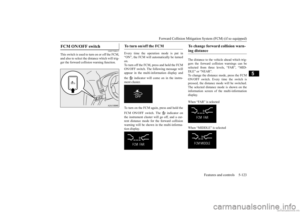
This switch is used to turn on or off the FCM, and also to select the distance which will trig- ger the forward collision warning function.
Every time the operation mode is put in “ON”, the FCM will automatically be turned on. To turn off the FCM, press and hold the FCMON/OFF switch. The following message will appear in the multi-information display and the indicator will come on in the instru- ment cluster. To turn on the FCM again, press and hold the FCM ON/OFF switch. The indicator on the instrument cluster will go off, and a cur- rent distance mode for the forward collisionwarning will be shown
in the multi-informa-
tion display.
The distance to the vehicle ahead which trig- gers the forward collision warnings can be selected from three levels, “FAR”, “MID- DLE” or “NEAR”.To change the distance mode, press the FCM ON/OFF switch. Every time the switch is pressed, the distance
mode will be switched.
The selected distance
mode is shown on the
information screen of
the multi-information
display. When “FAR” is selected When “MIDDLE” is selected
FCM ON/OFF switch
To turn on/off the FCM
To change forward collision warn- ing distance
BK0278200US.book 123 ページ 2019年4月10日 水曜日 午前10時59分
Page 205 of 443
Forward Collision Mitigation System (FCM) (if so equipped) 5-124 Features and controls
5
When “NEAR” is selected
N00594800037
If there is a malfunction in the system, a warning will appear on the information screen of the multi-information display depending on the situation.
N00594900041
When the FCM system determines that its performance has been degraded, the FCM will become inoperative.This can occur when
Foreign objects, such
as dirt, snow, ice,
mist or dew condensat
ion adhere to the
windshield of the sensor portion. In adverse weather conditions, such as rain, snow, sand storms, etc. A front vehicle or an oncoming vehicle is splashing water, snow or dirt.
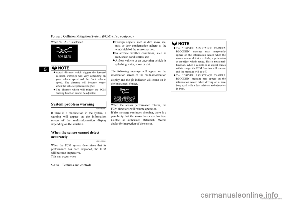
The following message will appear on the information screen of
the multi-information
display and the indicator will come on in the instrument cluster. When the sensor performance returns, the FCM functions will resume operation. If the message continues showing, there is apossibility that the se
nsor has a malfunction.
Contact an authorized Mitsubishi Motors dealer for inspection of the sensor.
NOTE
Actual distance which
triggers the forward
collision warnings wi
ll vary depending on
your vehicle speed a
nd the front vehicle
speed. The distance
will become longer
when the vehicle speeds are higher. The distance which will trigger the FCM braking function cannot be adjusted.
System problem warning
When the sensor cannot detect accurately
NOTE
The “DRIVER ASSISTANCE CAMERA BLOCKED” message may temporarilyappear on the information screen when thesensor cannot detect a
vehicle, a pedestrian
or an object within ra
nge. This is not a mal-
function. When a vehicle or an object comeswithin range, the FCM function will resume and the message will go off. The “DRIVER ASSISTANCE CAMERA BLOCKED” message
may appear on the
information screen when driving on a non-busy road with a few vehicles and obstacles in front.
BK0278200US.book 124 ページ 2019年4月10日 水曜日 午前10時59分
Page 206 of 443
Forward Collision Mitigation System (FCM) (if so equipped)
Features and controls 5-125
5
N00595100040
If the system becomes temporarily unavail- able for some reason, the following message will appear on the inform
ation screen of the
multi-information display, the indicator will come on in the instrument cluster, and the FCM will automatically be turned off. If the message continue
s showing, there is a
possibility that the FCM has a malfunction. Contact an authorized Mitsubishi Motors dealer for inspection of the system.
N00595200038
If the system becomes temporarily unavail- able due to the high or low temperature of the sensor, the following me
ssage will appear on
the information screen of the multi-informa- tion display, the indi
cator will come on in
the instrument cluster, and the FCM will automatically be turned off.After the temperature of the sensor has been in range, the system will automatically return to operation. If the message continues
showing, there is a
possibility that the FCM has a malfunction. Contact an authoriz
ed Mitsubishi Motors
dealer for inspection of the sensor.
N00595300042
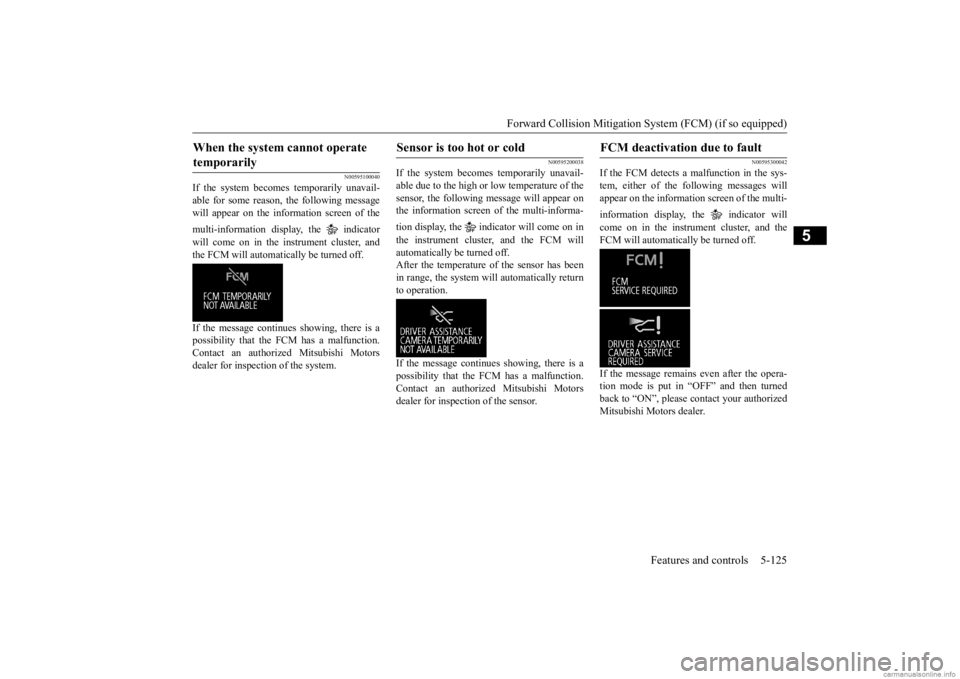
If the FCM detects a malfunction in the sys- tem, either of the following messages will appear on the informati
on screen of the multi-
information display, the indicator will come on in the instrument cluster, and the FCM will automatically be turned off. If the message remains even after the opera- tion mode is put in “OFF” and then turned back to “ON”, please contact your authorized Mitsubishi Motors dealer.
When the system cannot operate temporarily
Sensor is too hot or cold
FCM deactivation due to fault
BK0278200US.book 125 ページ 2019年4月10日 水曜日 午前10時59分
Page 210 of 443
Blind Spot Warning (BSW) (with Lane Change Assist) (if so equipped)
Features and controls 5-129
5
N00593500138
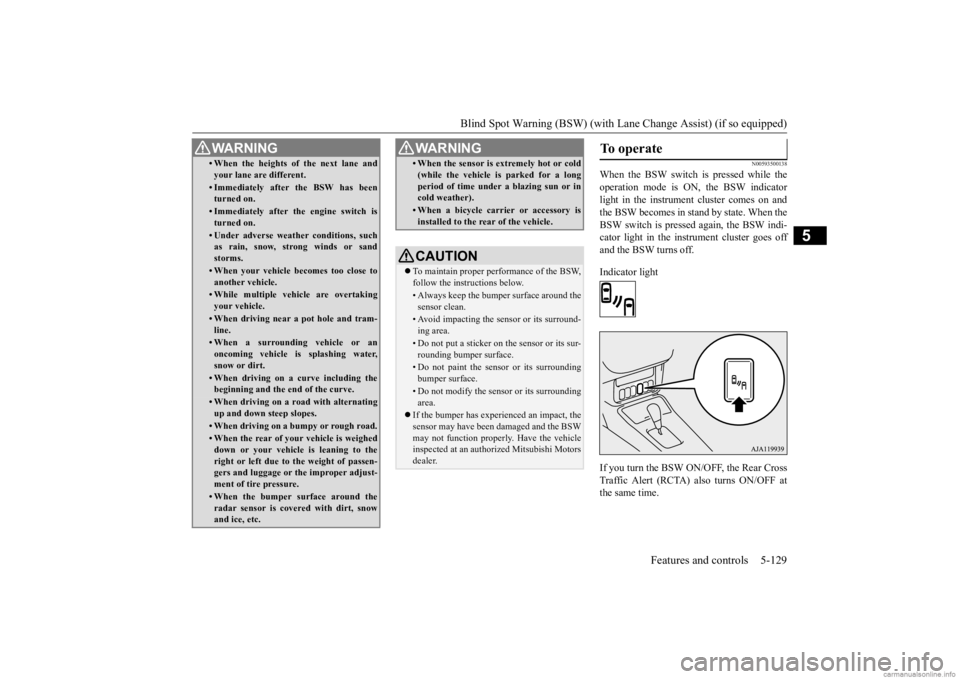
When the BSW switch is pressed while the operation mode is ON, the BSW indicator light in the instrument cluster comes on andthe BSW becomes in stand by state. When the BSW switch is pressed again, the BSW indi- cator light in the instrument cluster goes offand the BSW turns off. Indicator light If you turn the BSW ON/OFF, the Rear Cross Traffic Alert (RCTA) also turns ON/OFF atthe same time.
• When the heights of the next lane and your lane are different.• Immediately after the BSW has been turned on.• Immediately after the engine switch isturned on.• Under adverse weather conditions, suchas rain, snow, strong winds or sand storms.• When your vehicle becomes too close toanother vehicle.• While multiple ve
hicle are overtaking
your vehicle.• When driving near a pot hole and tram-line.• When a surroundin
g vehicle or an
oncoming vehicle is splashing water,snow or dirt.• When driving on a
curve including the
beginning and the end of the curve.• When driving on a r
oad with alternating
up and down steep slopes.• When driving on a bumpy or rough road.• When the rear of your vehicle is weigheddown or your vehicle
is leaning to the
right or left due to the weight of passen- gers and luggage or th
e improper adjust-
ment of tire pressure. • When the bumper su
rface around the
radar sensor is covered with dirt, snowand ice, etc.WA R N I N G
• When the sensor is extremely hot or cold(while the vehicle is parked for a longperiod of time unde
r a blazing sun or in
cold weather).• When a bicycle carrier or accessory isinstalled to the rear of the vehicle.CAUTION To maintain proper performance of the BSW, follow the instructions below.• Always keep the bumper surface around thesensor clean.• Avoid impacting the sensor or its surround-ing area.• Do not put a sticker on the sensor or its sur-rounding bumper surface.• Do not paint the sensor or its surroundingbumper surface.• Do not modify the sensor or its surroundingarea.
If the bumper has experienced an impact, the sensor may have been
damaged and the BSW
may not function properl
y. Have the vehicle
inspected at an authorized Mitsubishi Motorsdealer.WA R N I N G
To operate
BK0278200US.book 129 ページ 2019年4月10日 水曜日 午前10時59分
Page 237 of 443
Instrument cluster 5-156 Features and controls
5
N00519001473
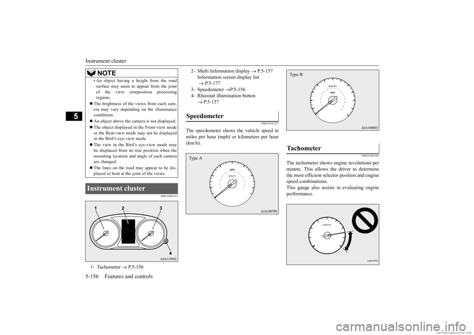
N00519101272
The speedometer shows the vehicle speed in miles per hour (mph) or kilometers per hour (km/h).
N00519201303
The tachometer shows e
ngine revolutions per
minute. This allows the driver to determine the most efficient selector position and engine speed combinations.This gauge also assists in evaluating engine performance.
• An object having a height from the road surface may seem to appear from the jointof the view composition processingregions.
The brightness of the views from each cam- era may vary depending on the illuminance conditions. An object above the came
ra is not displayed.
The object displayed in the Front-view mode or the Rear-view mode may not be displayed in the Bird’s eye-view mode. The view in the Bird’s eye-view mode may be displaced from its true position when the mounting location and a
ngle of each camera
are changed. The lines on the road may appear to be dis- placed or bent at th
e joint of the views.
Instrument cluster 1- Tachometer
P.5-156
NOTE
2- Multi Information display
P.5-157
Information screen display list P.5-177
3- Speedometer
P.5-156
4- Rheostat illu
mination button
P.5-157
Speedometer Type A
Tachometer Type B
BK0278200US.book 156 ページ 2019年4月10日 水曜日 午前10時59分