ABS MITSUBISHI OUTLANDER III 2016 Owners Manual
[x] Cancel search | Manufacturer: MITSUBISHI, Model Year: 2016, Model line: OUTLANDER III, Model: MITSUBISHI OUTLANDER III 2016Pages: 464, PDF Size: 60.77 MB
Page 67 of 464
Supplemental Restraint System (SRS) - airbag
Seat and restraint systems 4-41
4
N00408001616
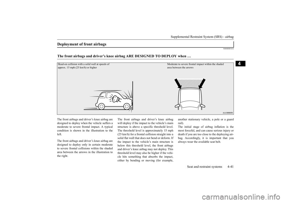
The front airbags and driver’s knee airbag are designed to deploy when
the vehicle suffers a
moderate to severe fro
ntal impact. A typical
condition is shown in th
e illustration to the
left. The front airbags and driver’s knee airbag are designed to deploy only in certain moderateto severe frontal collisions within the shaded area between the arrows in the illustration to the right.
The front airbags and driver’s knee airbag will deploy if the impact to the vehicle’s main structure is above a sp
ecific threshold level.
The threshold level is
approximately 15 mph
(25 km/h) for a frontal collision straight into a solid flat wall that does not bend or deform. Ifthe impact to the vehicle’s main structure is below this threshold le
vel, the front airbags
and driver’s knee airbag may not deploy. Thisthreshold level may also
be higher if the vehi-
cle hits something that absorbs the impact, either by bending or moving (for example,
another stationary vehi
cle, a pole or a guard
rail). The initial stage of airbag inflation is themost forceful, and can
cause serious injury or
death if you are too clos
e to the deploying air-
bag. Accordingly, it
is important that you
always wear the available seat belt.
Deployment of front airbags The front airbags and driver’s knee airb
ag ARE DESIGNED TO DEPLOY when …
Head-on collision with a solid wall at speeds of approx. 15 mph (25 km/h) or higher
Moderate to severe frontal
impact within the shaded
area between the arrows
BK0223400US.book 41 ページ 2015年2月13日 金曜日 午後12時15分
Page 68 of 464
Supplemental Restraint System (SRS) - airbag 4-42 Seat and restraint systems
4
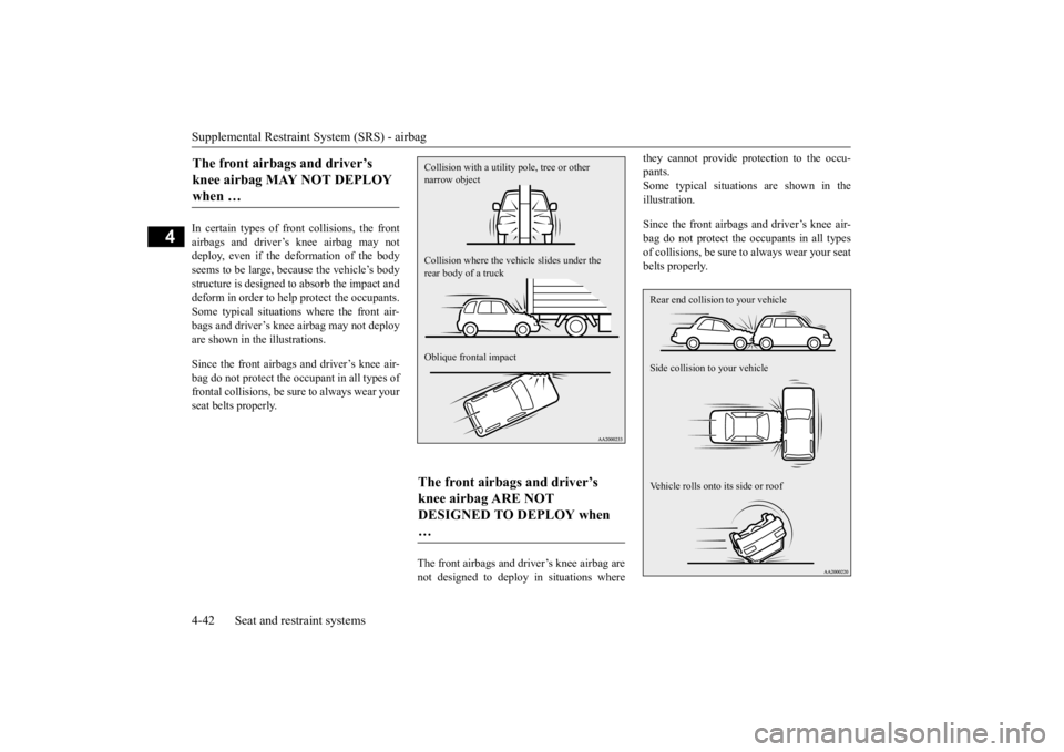
In certain types of front collisions, the front airbags and driver’s knee airbag may notdeploy, even if the deformation of the body seems to be large, because the vehicle’s body structure is designed to
absorb the impact and
deform in order to help
protect the occupants.
Some typical situations where the front air- bags and driver’s knee airbag may not deploy are shown in the illustrations. Since the front airbags and driver’s knee air- bag do not protect the oc
cupant in all types of
frontal collisions, be su
re to always wear your
seat belts properly.
The front airbags and driver’s knee airbag are not designed to deploy in situations where
they cannot provide protection to the occu- pants.Some typical situations are shown in the illustration. Since the front airbags and driver’s knee air- bag do not protect the oc
cupants in all types
of collisions, be sure
to always wear your seat
belts properly.
The front airbags and driver’s knee airbag MAY NOT DEPLOY when …
The front airbags and driver’s knee airbag ARE NOT DESIGNED TO DEPLOY when … Collision with a utility pole, tree or other narrow object Collision where the vehi
cle slides under the
rear body of a truck Oblique frontal impact
Rear end collision to your vehicle Side collision to your vehicle Vehicle rolls onto its side or roof
BK0223400US.book 42 ページ 2015年2月13日 金曜日 午後12時15分
Page 73 of 464
Supplemental Restraint System (SRS) - airbag
Seat and restraint systems 4-47
4
SRS side airbags and curtain airbags are designed to provide
additional protection.
Therefore, for your safety and the safety of all occupants, be sure to always wear your seat belts properly.
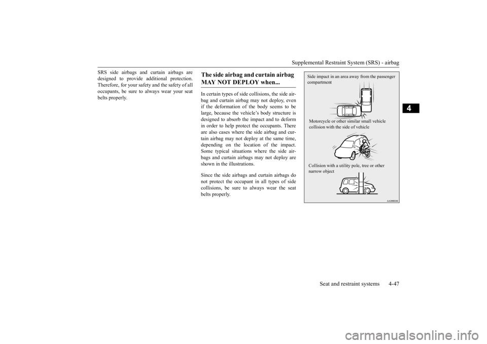
In certain types of side
collisions, the side air-
bag and curtain airbag may not deploy, evenif the deformation of the body seems to be large, because the vehicle’s body structure is designed to absorb the impact and to deformin order to help protect the occupants. There are also cases where the side airbag and cur- tain airbag may not de
ploy at the same time,
depending on the location of the impact. Some typical situations
where the side air-
bags and curtain airbags may not deploy are shown in the illustrations. Since the side airbags and curtain airbags do not protect the occupant in all types of sidecollisions, be sure to
always wear the seat
belts properly.The side airbag and curtain airbag MAY NOT DEPLOY when...
Side impact in an area away from the passenger compartment Motorcycle or other similar small vehicle collision with the side of vehicle Collision with a utility pole, tree or other narrow object
BK0223400US.book 47 ページ 2015年2月13日 金曜日 午後12時15分
Page 157 of 464
S-AWC (Super-All Wheel Co
ntrol) (if so equipped)
Features and controls 5-81
5
N00576600020
While the drive mode is in the “4WD AUTO” position, if the ECO mode switch is switched
ON, the drive mode will be changed to “4WD ECO” mode.If the ECO mode switch is switched OFF, the drive mode will be returned to “4WD AUTO” mode.Refer to the “ECO
mode switch” on page
5-184.
N00541301062
S-AWC is an integrat
ed vehicle dynamics
control system that helps enhance driving performance, cornering performance, and vehicle stability over a wide range of drivingconditions through integrated management of the electronically cont
rolled 4WD, the AYC
(Active Yaw Control), the ABS and the ASC.
CAUTION If the selected drive
mode indicator begins
blinking, the drive m
ode will automatically
switch to protect the drive-system compo-nents. A warning will
also be displayed in
the information screen in the multi informa- tion display. Warning display (color
liquid crystal dis-
play) Reduce speed and, if
the indicator stops
blinking, you may resume normal driving. For vehicles equipped with mono-color liq- uid crystal display mete
r, drive mode indica-
tor (“4WD-E”, “LOCK”) is blinking alternately
If the drive mode indi
cator (4WD) is blink-
ing, a problem has occurred with the elec-tronically controlled 4WD. A warning willalso be displayed in the information screen in the multi information display. Warning display (color liquid crystal dis- play) Have your vehicle in
spected by an autho-
rized Mitsubishi Motors dealer.For vehicles equipped
with mono-color liq-
uid crystal display mete
r, drive mode indica-
tor (“4WD-E”, “LOCK”) is blinking at thesame time. Make sure that all four tires are the same specified size, type, a
nd brand, and have no
significant difference
in the amount of wear.
Otherwise, the electronically controlled4WD system may not work properly, and the 4WD system warning (overheating or ser- vice required) may displayed.
When the ECO mode switch is ON
CAUTION
NOTE
If the drive mode is switched in any mode after the drive mode is switched in “4WD ECO”, the drive mode will not be changedeven if the ECO mode switch is switched OFF.
S-AWC (Super-All Wheel Control)
(if so equipped)
BK0223400US.book 81 ページ 2015年2月13日 金曜日 午後12時15分
Page 163 of 464
Inspection and maintenance following rough road operation
Features and controls 5-87
5
Your vehicle may not provide sufficient hill climbing ability and engine braking on steep slope. Avoid driving on steep slopes even though the vehicle is an 4-wheel drive vehi-cle.
N00537800085
If the electrical circuits become wet, furtheroperation of the vehi
cle will be impossible;
therefore, avoid drivi
ng through water unless
absolutely necessary. If driving through wateris unavoidable, use the following procedure:
Check the depth of the water and the terrain before attempting to drive through it. Driveslowly to avoid creating excessive water splashing.
N00530700085
After operating the vehicle in rough road con- ditions, be sure to perform the followinginspection and maintenance procedures:
Check that the vehicle has not been dam- aged by rocks, gravel, etc. Carefully wash the
vehicle with water.
Drive the vehicle sl
owly while lightly
depressing the brake pedal in order to dryout the brakes. If the brakes still do not function properly, contact an authorized Mitsubishi Motors dealer or a repair facil-ity of your choice as soon as possible to have the brakes checked. Remove the insects, dr
ied grass, etc. clog-
ging the radiator core. After driving through water, check the engine, transaxle and
differential oil. If
the oil or grease is milky or cloudy because of water cont
amination, it must
be replaced with new oil. Check the inside of the vehicle. If water entry is found, dry the carpet etc. Inspect the headlights. If water is in the headlight housing, have it drained at an authorized Mitsubishi Motors dealer or arepair facility of your choice.
NOTE
Avoid sudden braking,
sudden acceleration
and sharp turning; such operations couldresult in the vehicle becoming stuck. If the vehicle become
s stuck in sandy or
muddy roads, it can often be moved with arocking motion. Move the selector lever alternately between the “D” (DRIVE) and “R” (REVERSE) positi
ons while pressing
lightly on the ac
celerator pedal.
Driving on rough road can cause rust on the vehicle; wash the vehi
cle thoroughly as soon
as possible after such use.
Climbing/descending sharp grades Driving through water
CAUTION Never drive through water that is deep enough to cover wheel hubs, axles or exhaust pipe. Do not change th
e selector lever posi-
tion while driving through water. Frequent driving through water can adversely affect the life
span of the vehicle;
consult an authorized Mitsubishi Motors dealer or a repair facili
ty of your choice and
take the necessary measures to prepare,inspect, and repair the vehicle. After driving through water, apply the brakes to be sure they are
functioning properly. If
the brakes are wet a
nd not functioning prop-
erly, dry them out by driving slowly whilelightly depressing the brake pedal. Inspect each part of the vehicle carefully.
Inspection and maintenance following rough road opera-tion
BK0223400US.book 87 ページ 2015年2月13日 金曜日 午後12時15分
Page 180 of 464
Adaptive Cruise Control System (ACC) (if so equipped) 5-104 Features and controls
5
N00581300025
The speed of your vehicle will be maintained at the speed you have set. The speed can be set between approximately 25 mph (40 km/h) and 110 mph (180 km/h).
N00581400039
The ACC will maintain the distance to thefront vehicle and will apply the brakes auto-matically when the system judges braking is necessary. The distance
can be selected from
three levels. When the front vehicle stops, the ACC will automatically apply the brakes to stop yourvehicle. A few seconds after your vehicle has stopped, the ACC will release the brakes and yourvehicle will start to move or creep slowly. You must apply the brakes to keep your vehi- cle stationary.
When the ACC no longer detects a vehicle in front, the buzzer will sound, the vehicle sym-bol in the display will disappear and your
• While ABS, ASC or TCL is activated. • When the selector leve
r is in positions other
than “D” (DRIVE) and “Ds” (DOWN- SHIFT & SPORTY DRIVING). • While the brake pedal is depressed. • While the parking brake is engaged.• When the ACC system has judged that the performance for detect
ing a front vehicle is
degraded. • When an abnormality
in the ACC system
has been detected.
When ACC detects no vehicle in front within the set distance
NOTE
If the vehicle speed exceeds the set speed on a down slope, the system will automatically apply the brake to main
tain the vehicle set
speed.NOTE
When ACC detects a vehicle in front within the set distance
NOTE
If the brake pedal is not depressed within 2 seconds after your vehi
cle has been stopped
by the ACC, a warni
ng buzzer will sound,
the above warning will be shown in the multi information display to alert the driver, and the ACC control will be canceled. When depressing the brake pedal while the automatic brake is applied, the brake pedalwill feel firm. This is normal. Depress the brake pedal harder to apply greater braking force. During the automatic
braking, operation
sounds may be heard. This is normal.WA R N I N G Never leave the vehicle while it is being stopped by the ACC.
BK0223400US.book 104 ページ 2015年2月13日 金曜日 午後12時15分
Page 185 of 464
Adaptive Cruise Control System (ACC) (if so equipped)
Features and controls 5-109
5
When the ACC is canceled, the “SET” indi- cator goes off and the following distance indi-cator turns to the ‘standby’ display. The front vehicle indicator also turns to the ‘standby’ display when a front vehicle is detected. In any of the situations listed below, the ACC control is automatically canceled, a buzzer sounds and a message is shown in the multi-information display.
When your vehicle stops. When the ASC is turned off. While ABS, ASC or TCL is activated. When the selector lever is in a position other than “D” (DRIVE) and “Ds” (DOWNSHIFT & SPORTY DRIVING). When the parking brake is engaged.
When the ACC system determines that its performance has been degraded, a buzzer will sound and a message will
be displayed in the
multi information display.
This can occur when In adverse weather conditions, such as rain, snow or sand storms, etc. Foreign objects, such as dirt, snow or ice, adhere to the surface
of the radar sensor.
A front vehicle or an oncoming vehicle is splashing water, snow or dirt. Driving on a nonbusy road with a few vehicles and obsta
cles in front.
The brake pads are overheating.
If the display keeps showing the message, there is a possibility that the ACC has a mal-function. Contact your
authorized Mitsubishi
Motors dealer. When the ACC system detects an abnormal- ity in the system, th
e ACC system will be
turned off, a buzzer w
ill sound and a message
will be displayed in the multi information dis- play. If the message remains after the opera-tion mode has been turned to the “OFF” position and then turned back to the “ON” position, contact your
authorized Mitsubishi
Motors dealer.
NOTE
You can also cancel the ACC control by pressing the “ACC ON/OFF” switch. If thisswitch is pressed while the ACC is “ON”,the ACC will be turned off.
BK0223400US.book 109 ページ 2015年2月13日 金曜日 午後12時15分
Page 186 of 464
Adaptive Cruise Control System (ACC) (if so equipped) 5-110 Features and controls
5
N00581800033
After the ACC control has been canceled with the ACC turned on, the ACC control can beresumed by pushing up
and releasing the
“RES +” switch.
N00581900021
With the ACC turned on, the distance between your vehicle an
d a vehicle ahead can
be selected from thre
e levels by pushing the
ACC distance switch. Each time the ACC distance switch is pus
hed, the following dis-
tance will change from “Long” to “Middle”, to “Short”, and return to “Long” again.Every time the ACC is turned to ON, the followingdistance is reset to “Long”.
The following distance indicator shows the level of the following distance:“Long” “Middle” “Short”
N00582000029
Press and hold the “ACC ON/OFF” switch while the operation mode is in the “ON” posi- tion. A buzzer will s
ound and the multi infor-
mation display will show the following indicator.
To resume the control
NOTE
When any of the following conditions are present, the ACC cont
rol cannot be resumed.
• When your vehicle speed is lower than approximately 6 mph (10 km/h) or higherthan 110 mph (180 km/h). • When your vehicle is driven at speeds between approximately 6 mph (10 km/h) and 25 mph (40 km/h) and the ACC is not detecting a vehi
cle in front.
• When ASC is in the OFF position. • While ABS, ASC or TCL is activated. • When the selector leve
r is in positions other
than “D” (DRIVE) and “Ds” (DOWN- SHIFT & SPORTY DRIVING). • While the brake pedal is depressed.
• While the parking brake is engaged.• When the ACC system has judged that the performance for detec
ting a front vehicle is
degraded. • When an abnormality in the ACC system has been detected.
To change the following dis- tance
NOTE
NOTE
Actual distance will vary depending on your vehicle speed and the front vehicle speed.The distance will become longer when thevehicle speeds are higher.
To activate conventional cruise control
BK0223400US.book 110 ページ 2015年2月13日 金曜日 午後12時15分
Page 328 of 464

Trailer towing 6-16 Driving safety
6
1. Apply the brakes a
nd keep them applied.
2. Have someone plac
e chocks or blocks
under both the vehicle and trailer wheels. 3. When the chocks or blocks are in place, release your brakes slowly until thechocks or blocks absorb the load. 4. Apply the parking brake firmly. 5. Set the selector lever to the “P” (PARK)position and turn off the engine.
When restarting out after parking on a hill: 1. Check that the selector lever is set to the “P” (PARK) position.2. Start the engine. Be sure to keep the brake pedal depressed. 3. Set the selector lever to the “D” (DRIVE)position or “R” (REVERSE) position. 4. Release the parking brake and brake pedal and slowly pull or back away from thechocks or blocks. Stop and apply your brakes. 5. Have someone retrieve the chocks orblocks.
BK0223400US.book 16 ページ 2015年2月13日 金曜日 午後12時15分
Page 395 of 464
How to change a tire
For emergencies 8-13
8
N00849401235
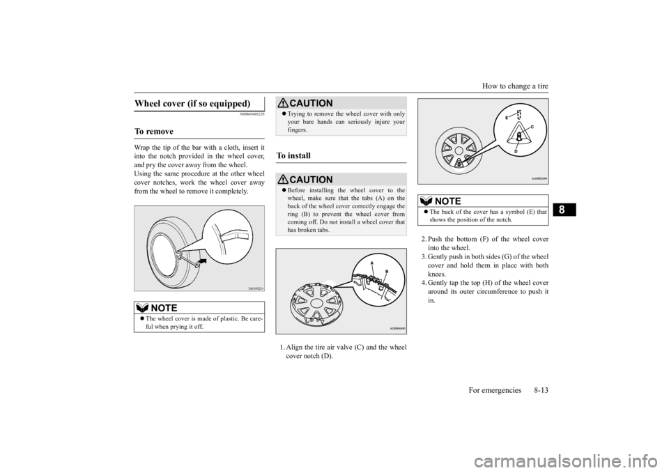
Wrap the tip of the bar with a cloth, insert it into the notch provided in the wheel cover, and pry the cover away from the wheel. Using the same procedur
e at the other wheel
cover notches, work the wheel cover away from the wheel to remove it completely.
1. Align the tire air valve (C) and the wheel cover notch (D).
2. Push the bottom (F) of the wheel cover into the wheel. 3. Gently push in both sides (G) of the wheel cover and hold them in place with both knees. 4. Gently tap the top (H) of the wheel coveraround its outer circumference to push it in.
Wheel cover (if so equipped) To remove
NOTE
The wheel cover is made
of plastic. Be care-
ful when prying it off.
CAUTION Trying to remove the
wheel cover with only
your bare hands can se
riously injure your
fingers.
To install
CAUTION Before installing the wheel cover to the wheel, make sure that the tabs (A) on the back of the wheel cove
r correctly engage the
ring (B) to prevent the wheel cover fromcoming off. Do not install a wheel cover that has broken tabs.
NOTE
The back of the cover has a symbol (E) that shows the position of the notch.
BK0223400US.book 13 ページ 2015年2月13日 金曜日 午後12時15分