light MITSUBISHI OUTLANDER PHEV 2016 (in English) Service Manual
[x] Cancel search | Manufacturer: MITSUBISHI, Model Year: 2016, Model line: OUTLANDER PHEV, Model: MITSUBISHI OUTLANDER PHEV 2016Pages: 490, PDF Size: 22.02 MB
Page 250 of 490
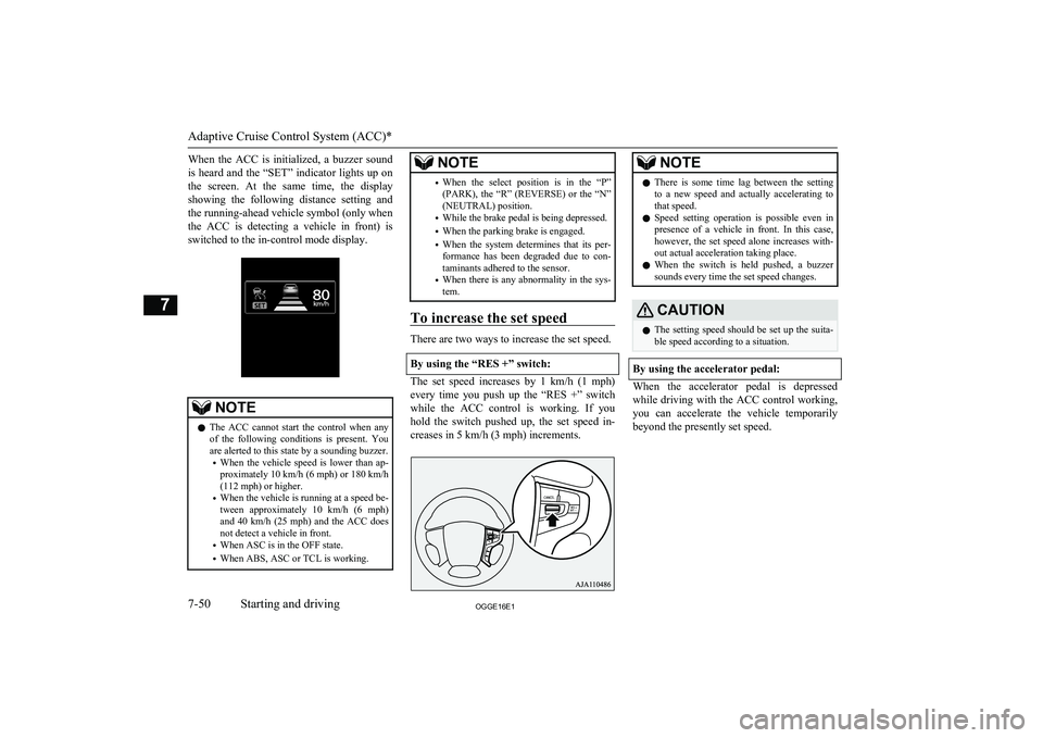
When the ACC is initialized, a buzzer soundis heard and the “SET” indicator lights up on the screen. At the same time, the display showing the following distance setting and
the running-ahead vehicle symbol (only when
the ACC is detecting a vehicle in front) is switched to the in-control mode display.NOTEl The ACC cannot start the control when any
of the following conditions is present. You
are alerted to this state by a sounding buzzer.
• When the vehicle speed is lower than ap-
proximately 10 km/h (6 mph) or 180 km/h
(112 mph) or higher.
• When the vehicle is running at a speed be-
tween approximately 10 km/h (6 mph)
and 40 km/h (25 mph) and the ACC does
not detect a vehicle in front.
• When ASC is in the OFF state.
• When ABS, ASC or TCL is working.NOTE•When the select position is in the “P”
(PARK), the “R” (REVERSE) or the “N”
(NEUTRAL) position.
• While the brake pedal is being depressed.
• When the parking brake is engaged.
• When the system determines that its per-
formance has been degraded due to con-
taminants adhered to the sensor.
• When there is any abnormality in the sys-
tem.
To increase the set speed
There are two ways to increase the set speed.
By using the “RES +” switch:
The set speed increases by 1 km/h (1 mph) every time you push up the “RES +” switch
while the ACC control is working. If you hold the switch pushed up, the set speed in-creases in 5 km/h (3 mph) increments.
NOTEl There is some time lag between the setting
to a new speed and actually accelerating tothat speed.
l Speed setting operation is possible even in
presence of a vehicle in front. In this case, however, the set speed alone increases with-
out actual acceleration taking place.
l When the switch is held pushed, a buzzer
sounds every time the set speed changes.CAUTIONl The setting speed should be set up the suita-
ble speed according to a situation.
By using the accelerator pedal:
When the accelerator pedal is depressed
while driving with the ACC control working,you can accelerate the vehicle temporarily
beyond the presently set speed.
Adaptive Cruise Control System (ACC)*
7-50OGGE16E1Starting and driving7
Page 253 of 490
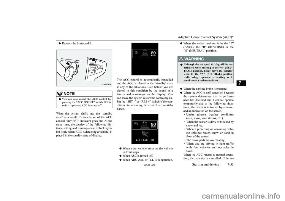
lDepress the brake pedal.NOTElYou can also cancel the ACC control by
pressing the “ACC ON/OFF” switch. If thisswitch is pressed, ACC is turned off.
When the system shifts into the ‘standby
state’ as a result of cancellation of the ACC
control, the“ SET” indicator goes out. At the same time, the display of the following dis-
tance setting and running-ahead vehicle sym- bol (only when ACC is detecting a vehicle) is
placed in the standby state of display.
The ACC control is automatically cancelled
and the ACC is placed in the ‘standby’ state
in any of the situations listed below; you are
alerted to this condition by the sound of a
buzzer and a message on the display. You can make the system restart the control by us-ing the “SET -” or “RES +” switch if the con-
ditions for resuming the control are reestab-
lished.
l When your vehicle stops as the vehicle
in front stops.
l When ASC is turned off.
l When ABS, ASC or TCL is in operation.
lWhen the select position is in the “P”
(PARK), the “R” (REVERSE) or the “N” (NEUTRAL) position.WARNINGl Although the set speed driving will be de-
activated when shifting to the “N” (NEU- TRAL) position, never move the selector
lever to the “N” (NEUTRAL) position
while using regenerative braking as it could cause a serious accident.
l When the parking brake is engaged.
l When the ACC is self-cancelled because
the system determines that its perform- ance has declined and it cannot operate
temporarily due to the following situa- tions, the driver is informed by a buzzer
and an indication on the screen. • Under adverse weather conditions
(rain, snow, sand storms, etc.).
• When the sensor is dirty or blocked by
snow and ice.
• When a preceding or oncoming vehi-
cle splashes water, snow or sand in front of the sensor.
• The brake pads are overheating.
• When you are driving in light traffic
with few vehicles and obstacles in front.
When the ACC returns to normal opera-
tion, the indicator is cancelled. If the in-
Adaptive Cruise Control System (ACC)*
7-53OGGE16E1Starting and driving7
Page 258 of 490
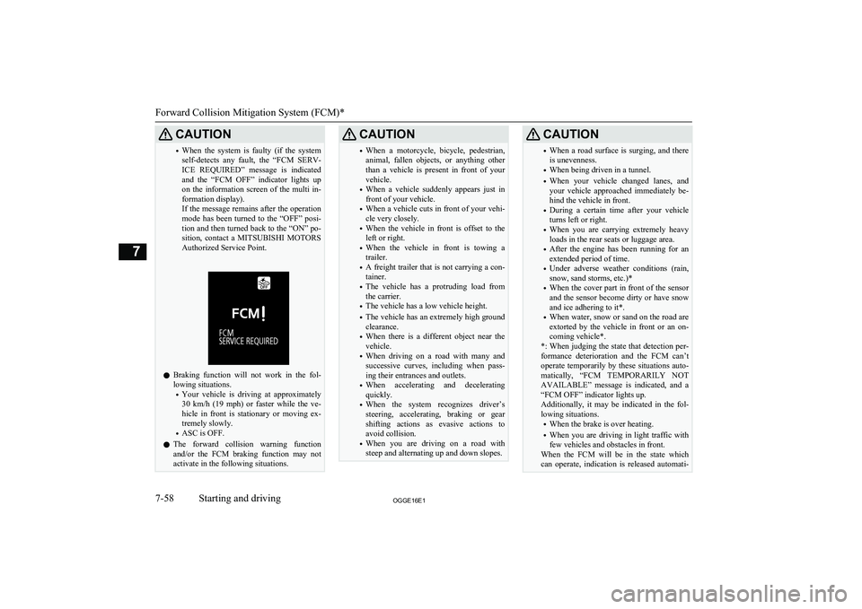
CAUTION•When the system is faulty (if the system
self-detects any fault, the “FCM SERV- ICE REQUIRED” message is indicated
and the “FCM OFF” indicator lights up on the information screen of the multi in- formation display).
If the message remains after the operation
mode has been turned to the “OFF” posi- tion and then turned back to the “ON” po-
sition, contact a MITSUBISHI MOTORS
Authorized Service Point.
l Braking function will not work in the fol-
lowing situations.
• Your vehicle is driving at approximately
30 km/h (19 mph) or faster while the ve-
hicle in front is stationary or moving ex- tremely slowly.
• ASC is OFF.
l The forward collision warning function
and/or the FCM braking function may not
activate in the following situations.
CAUTION• When a motorcycle, bicycle, pedestrian,
animal, fallen objects, or anything other
than a vehicle is present in front of your vehicle.
• When a vehicle suddenly appears just in
front of your vehicle.
• When a vehicle cuts in front of your vehi-
cle very closely.
• When the vehicle in front is offset to the
left or right.
• When the vehicle in front is towing a
trailer.
• A freight trailer that is not carrying a con-
tainer.
• The vehicle has a protruding load from
the carrier.
• The vehicle has a low vehicle height.
• The vehicle has an extremely high ground
clearance.
• When there is a different object near the
vehicle.
• When driving on a road with many and
successive curves, including when pass-
ing their entrances and outlets.
• When accelerating and decelerating
quickly.
• When the system recognizes driver’s
steering, accelerating, braking or gear
shifting actions as evasive actions to
avoid collision.
• When you are driving on a road with
steep and alternating up and down slopes.CAUTION• When a road surface is surging, and there
is unevenness.
• When being driven in a tunnel.
• When your vehicle changed lanes, and
your vehicle approached immediately be- hind the vehicle in front.
• During a certain time after your vehicle
turns left or right.
• When you are carrying extremely heavy
loads in the rear seats or luggage area.
• After the engine has been running for an
extended period of time.
• Under adverse weather conditions (rain,
snow, sand storms, etc.)*
• When the cover part in front of the sensor
and the sensor become dirty or have snow
and ice adhering to it*.
• When water, snow or sand on the road are
extorted by the vehicle in front or an on- coming vehicle*.
*: When judging the state that detection per- formance deterioration and the FCM can’t operate temporarily by these situations auto-
matically, “FCM TEMPORARILY NOT
AVAILABLE” message is indicated, and a “FCM OFF” indicator lights up.
Additionally, it may be indicated in the fol- lowing situations.
• When the brake is over heating.
• When you are driving in light traffic with
few vehicles and obstacles in front.
When the FCM will be in the state which
can operate, indication is released automati-
Forward Collision Mitigation System (FCM)*
7-58OGGE16E1Starting and driving7
Page 264 of 490
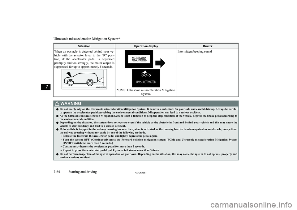
SituationOperation displayBuzzerWhen an obstacle is detected behind your ve-hicle with the selector lever in the “R” posi-
tion, if the accelerator pedal is depressed promptly and too strongly, the motor output is suppressed for up to approximately 5 seconds.
*UMS: Ultrasonic misacceleration Mitigation
System
Intermittent beeping soundWARNINGlDo not overly rely on the Ultrasonic misacceleration Mitigation System. It is never a substitute for your safe and careful driving. Always be careful
to operate the accelerator pedal perceiving the environmental conditions. Misoperation can lead to a serious accident.
l As the Ultrasonic misacceleration Mitigation System is not a function to keep the stop condition of the vehicle, depress the brake pedal according to
the environmental condition.
l Depending on the situation, the system does not operate even if the vehicle or the obstacle in front and behind your vehicle and this may cause the
vehicle to start suddenly and lead to a serious accident.
l If the vehicle is trapped in the railway crossing because the system is activated as the crossing barrier is misrecognised as an obstacle, escape from
the railway crossing without any panic by one of the following methods.
• Release the foot from the accelerator pedal and lightly depress the pedal again.
• Turn the system OFF. (Continuously press the Forward collision mitigation system (FCM) and Ultrasonic misacceleration Mitigation System
ON/OFF switch for more than 3 seconds.)
• Continuously depress the accelerator pedal for more than 5 seconds.
• Repeat to press the accelerator pedal quickly to its full stroke more than 3 times.
l Do not perform inspection of the system operation on your own. Depending on the situation, this may cause the system to not operate properly and
lead to a serious accident.
Ultrasonic misacceleration Mitigation System*
7-64OGGE16E1Starting and driving7
Page 267 of 490
CAUTIONlImproperly handling the system components may result in such problems as degraded sensor performance and ultimately in an accident.
Be sure to take the following precautions to keep the system in good operating conditions.
• Avoid application of strong shock loads to the sensor.
• The sensor should be kept clean.
• Do not cover the sensor with a sticker or anything.
• Do not modify the suspension of your vehicle.
l If the bumper has been exposed to an impact, the sensors may fail and prevent the system from functioning properly. Have the vehicle inspected a
MITSUBISHI MOTORS Authorized Service Point.
Obstacle detection areas
E00643500047
The detection areas of the sensors are limited.
Moreover, the sensors are unable to detect
low or thin objects or objects near the rear
bumper. Make sure to check the surroundings
as you operate the vehicle in a safe manner.
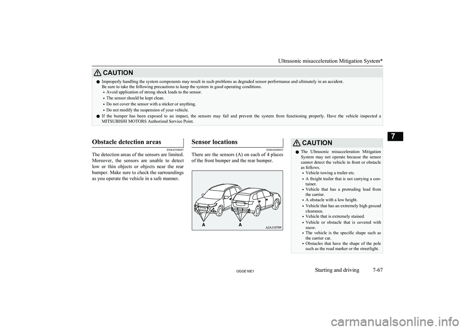
Sensor locations
E00643600035
There are the sensors (A) on each of 4 places
of the front bumper and the rear bumper.
CAUTIONl The Ultrasonic misacceleration Mitigation
System may not operate because the sensor
cannot detect the vehicle in front or obstacle as follows.
• Vehicle towing a trailer etc.
• A freight trailer that is not carrying a con-
tainer.
• Vehicle that has a protruding load from
the carrier.
• A obstacle with a low height.
• Vehicle that has an extremely high ground
clearance.
• Vehicle that is extremely stained.
• Vehicle or obstacle that is covered with
snow.
• The vehicle is the specific shape such as
the carrier car.
• Obstacles that have the shape of the pole
such as the road marker or the streetlight.
Ultrasonic misacceleration Mitigation System*
7-67OGGE16E1Starting and driving7
Page 271 of 490
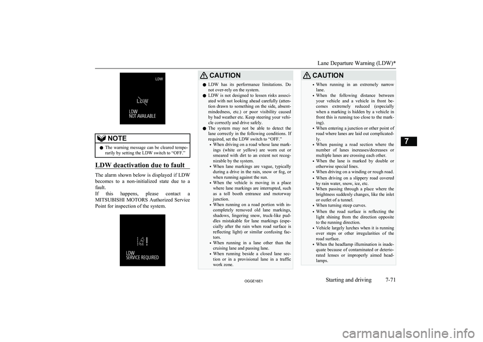
NOTElThe warning message can be cleared tempo-
rarily by setting the LDW switch to “OFF.”
LDW deactivation due to fault
The alarm shown below is displayed if LDW
becomes to a non-initialized state due to a
fault.
If this happens, please contact a
MITSUBISHI MOTORS Authorized Service
Point for inspection of the system.
CAUTIONl LDW has its performance limitations. Do
not over-rely on the system.
l LDW is not designed to lessen risks associ-
ated with not looking ahead carefully (atten-
tion drawn to something on the side, absent-
mindedness, etc.) or poor visibility caused
by bad weather etc. Keep steering your vehi-
cle correctly and drive safely.
l The system may not be able to detect the
lane correctly in the following conditions. If required, set the LDW switch to “OFF.”
• When driving on a road whose lane mark-
ings (white or yellow) are worn out or
smeared with dirt to an extent not recog- nizable by the system.
• When lane markings are vague, typically
during a drive in the rain, snow or fog, or when running against the sun.
• When the vehicle is moving in a place
where lane markings are interrupted, such
as a toll booth entrance and motorway junction.
• When running on a road portion with in-
completely removed old lane markings,
shadows, lingering snow, truck-like pud- dles mistakable for lane markings (espe-cially after the rain when road surface is
reflecting light) or similar confusing fac- tors.
• When running in a lane other than the
cruising lane and passing lane.
• When running beside a closed lane sec-
tion or in a provisional lane in a traffic
work zone.CAUTION• When running in an extremely narrow
lane.
• When the following distance between
your vehicle and a vehicle in front be-
comes extremely reduced (especially when a marking is hidden by a vehicle in
front this is running too close to the mark- ing).
• When entering a junction or other point of
road where lanes are laid out complicated-ly.
• When passing a road section where the
number of lanes increases/decreases or
multiple lanes are crossing each other.
• When the lane is marked by double or
otherwise special lines.
• When driving on a winding or rough road.
• When driving on a slippery road covered
by rain water, snow, ice, etc.
• When passing through a place where the
brightness suddenly changes, like the inlet or outlet of a tunnel.
• When turning steep curves.
• When the road surface is reflecting the
light shining from the direction opposite
to the running direction.
• Vehicle largely lurches when it is running
over steps or other irregularities of the
road surface.
• When the headlamp illumination is inade-
quate because of contaminated or deterio-
rated lenses or improperly aimed head- lamps.
Lane Departure Warning (LDW)*
7-71OGGE16E1Starting and driving7
Page 276 of 490
1.Operate the multi-information display
switch to switch the information screen
to the menu screen.
Refer to “Multi information display switch” on page 6-05.
Refer to “Changing the function set- tings” on page 6-16.
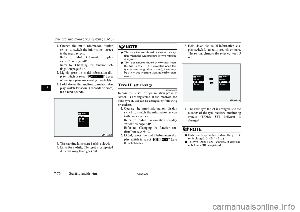
2. Lightly press the multi-information dis-
play switch to select “
” (reset
of low tyre pressure warning threshold).
3. Hold down the multi-information dis-
play switch for about 3 seconds or more, the buzzer sounds.
4. The warning lamp start flashing slowly.
5. Drive for a while. The reset is completed
if the warning lamp goes out.
NOTEl The reset function should be executed every
time when the tyre pressure or tyre rotationis adjusted.
l The reset function should be executed when
the tyre is cold. If it is executed when the
tyre is warm (e.g. after driving), there may be a low tyre pressure warning earlier than
usual.Tyre ID set change
E00637600072
In case that 2 sets of tyre inflation pressure
sensor ID are registered in the receiver, the
valid tyre ID set can be changed by following
procedure. 1. Operate the multi-information display
switch to switch the information screen
to the menu screen.
Refer to “Multi information display switch” on page 6-05.
Refer to “Changing the function set- tings” on page 6-16.
2. Lightly press the multi-information dis-
play switch to select “
” (tyre
ID set change).
3. Hold down the multi-information dis-
play switch for about 3 seconds or more. The setting changes the selected tyre ID set.
4. The valid tyre ID set is changed, and the
number of the tyre pressure monitoring
system (TPMS) SET indicator is changed.
NOTEl Each time this procedure is done, the tyre ID
set is changed. (1 - 2 - 1 - 2 …)
l The tyre ID set is NOT changed, in case that
only 1 set of ID is registered.
Tyre pressure monitoring system (TPMS)
7-76OGGE16E1Starting and driving7
Page 286 of 490
NOTElBecause the rear-view camera has a special
lens, the lines on the ground between park-
ing spaces may not look parallel on the screen.
l In the following situations, the screen indi-
cation may be difficult to see. There is no abnormality.
• Low light (nighttime)
• When the light of the sun or the light from
a vehicle’s headlamps shines directly into the lens
l If the camera is hot and is then cooled by
rain or a car wash, the lens can mist up. This phenomenon does not indicate a malfunc-
tion.
l It is not possible to fully see obstacles when
the lens is dirty. If the lens becomes conta-
minated by water droplets, snow, mud or oil, wipe off the contamination, taking care not
to scratch the lens.
l Please observe the following cautions. Ig-
noring them could lead to a camera malfunc-tion.
• Do not subject the camera to physical
shock.
• Do not apply wax to the camera.
• Do not splash the camera with boiling wa-
ter.
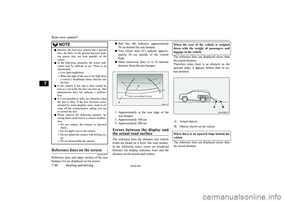
• Do not disassemble the camera.Reference lines on the screen
E00649100029
Reference lines and upper surface of the rear
bumper (A) are displayed on the screen.
l Red line (B) indicates approximately
50 cm behind the rear bumper.
l Two Green lines (C) indicate approxi-
mately 20 cm outside of the vehicle
body.
l Short transverse lines (1 to 3) indicate
distance from the rear bumper.Check surroundings for safety.
1. Approximately at the rear edge of the
rear bumper
2. Approximately 100 cm
3. Approximately 200 cm
Errors between the display and the actual road surface
The reference lines for distance and vehicle
width are based on a level, flat road surface. In the following cases, errors are produced between the display reference lines and the distance on the actual road surface.
When the rear of the vehicle is weighed
down with the weight of passengers and luggage in the vehicle
The reference lines are displayed closer than
the actual distance.
Therefore when there is an obstacle on the
upward slope, it appears farther than its ac- tual position.
A:Actual objectsB:Objects shown on the screen
When there is an upward slope behind the
vehicle
The reference lines are displayed closer than the actual distance.
Rear-view camera*
7-86OGGE16E1Starting and driving7
Page 290 of 490
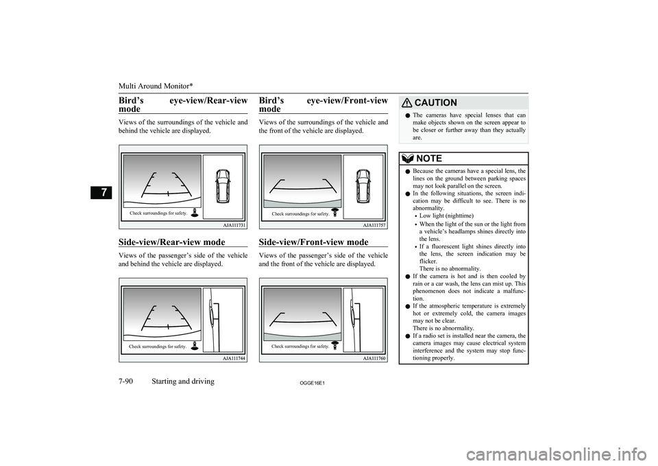
Bird’s eye-view/Rear-viewmode
Views of the surroundings of the vehicle and
behind the vehicle are displayed.
Side-view/Rear-view mode
Views of the passenger’s side of the vehicle and behind the vehicle are displayed.
Bird’s eye-view/Front-view
mode
Views of the surroundings of the vehicle and
the front of the vehicle are displayed.
Side-view/Front-view mode
Views of the passenger’s side of the vehicle and the front of the vehicle are displayed.
CAUTIONl The cameras have special lenses that can
make objects shown on the screen appear to be closer or further away than they actually
are.NOTEl Because the cameras have a special lens, the
lines on the ground between parking spaces
may not look parallel on the screen.
l In the following situations, the screen indi-
cation may be difficult to see. There is no abnormality.
• Low light (nighttime)
• When the light of the sun or the light from
a vehicle’s headlamps shines directly into
the lens.
• If a fluorescent light shines directly into
the lens, the screen indication may be
flicker.
There is no abnormality.
l If the camera is hot and is then cooled by
rain or a car wash, the lens can mist up. This
phenomenon does not indicate a malfunc- tion.
l If the atmospheric temperature is extremely
hot or extremely cold, the camera images
may not be clear.
There is no abnormality.
l If a radio set is installed near the camera, the
camera images may cause electrical system interference and the system may stop func-tioning properly.
Multi Around Monitor*
7-90OGGE16E1Starting and driving7Check surroundings for safety. Check surroundings for safety. Check surroundings for safety. Check surroundings for safety.
Page 298 of 490
If you tow a trailer at an altitude of more than
1,000 m above sea-level, reduce your weight by 10 % of the gross combination weight for
every increase of 1,000 m above sea-level, as
the engine output is lowered owing to de-
crease in atmospheric pressure.
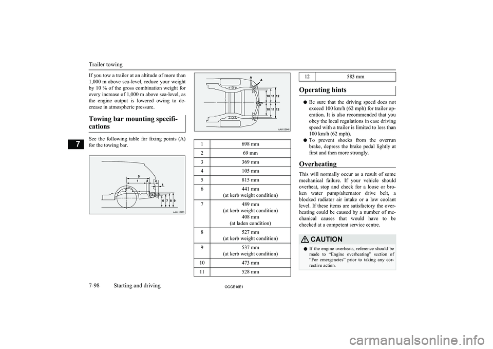
Towing bar mounting specifi- cations
See the following table for fixing points (A) for the towing bar.
1698 mm269 mm3369 mm4105 mm5815 mm6441 mm
(at kerb weight condition)7489 mm
(at kerb weight condition) 408 mm
(at laden condition)8527 mm
(at kerb weight condition)9537 mm
(at kerb weight condition)10473 mm11528 mm12583 mm
Operating hints
l Be sure that the driving speed does not
exceed 100 km/h (62 mph) for trailer op-
eration. It is also recommended that you obey the local regulations in case driving speed with a trailer is limited to less than
100 km/h (62 mph).
l To prevent shocks from the overrun
brake, depress the brake pedal lightly at first and then more strongly.
Overheating
This will normally occur as a result of some
mechanical failure. If your vehicle should overheat, stop and check for a loose or bro-ken water pump/alternator drive belt, a
blocked radiator air intake or a low coolant level. If these items are satisfactory the over-
heating could be caused by a number of me-
chanical causes that would have to be
checked at a competent service centre.
CAUTIONl If the engine overheats, reference should be
made to “Engine overheating” section of
“For emergencies” prior to taking any cor- rective action.
Trailer towing
7-98OGGE16E1Starting and driving7