phone MITSUBISHI OUTLANDER PHEV 2017 Owner's Manual (in English)
[x] Cancel search | Manufacturer: MITSUBISHI, Model Year: 2017, Model line: OUTLANDER PHEV, Model: MITSUBISHI OUTLANDER PHEV 2017Pages: 548, PDF Size: 25.5 MB
Page 5 of 548
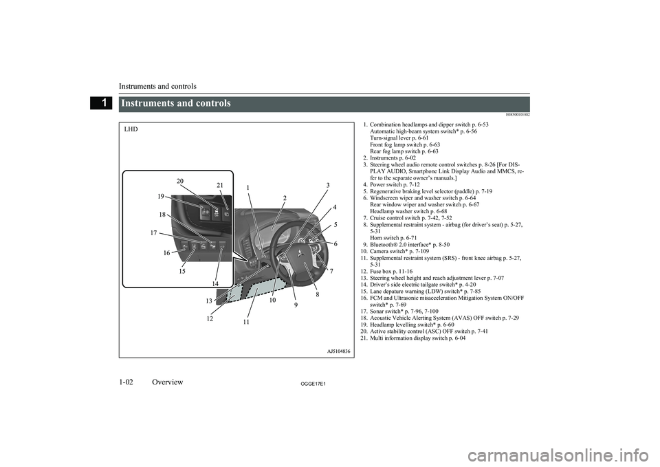
Instruments and controlsE085001018821. Combination headlamps and dipper switch p. 6-53Automatic high-beam system switch* p. 6-56
Turn-signal lever p. 6-61
Front fog lamp switch p. 6-63
Rear fog lamp switch p. 6-63
2. Instruments p. 6-02
3. Steering wheel audio remote control switches p. 8-26 [For DIS- PLAY AUDIO, Smartphone Link Display Audio and MMCS, re-
fer to the separate owner’s manuals.]
4. Power switch p. 7-12
5. Regenerative braking level selector (paddle) p. 7-19
6. Windscreen wiper and washer switch p. 6-64 Rear window wiper and washer switch p. 6-67
Headlamp washer switch p. 6-68
7. Cruise control switch p. 7-42, 7-52
8. Supplemental restraint system - airbag (for driver’s seat) p. 5-27, 5-31
Horn switch p. 6-71
9. Bluetooth® 2.0 interface* p. 8-50
10. Camera switch* p. 7-109
11. Supplemental restraint system (SRS) - front knee airbag p. 5-27, 5-31
12. Fuse box p. 11-16
13. Steering wheel height and reach adjustment lever p. 7-07
14. Driver’s side electric tailgate switch* p. 4-20
15. Lane depature warning (LDW) switch* p. 7-85
16. FCM and Ultrasonic misacceleration Mitigation System ON/OFF switch* p. 7-69
17. Sonar switch* p. 7-96, 7-100
18. Acoustic Vehicle Alerting System (AVAS) OFF switch p. 7-29
19. Headlamp levelling switch* p. 6-60
20. Active stability control (ASC) OFF switch p. 7-41
21. Multi information display switch p. 6-04
Instruments and controls
1-02OGGE17E1Overview1LHD
Page 6 of 548
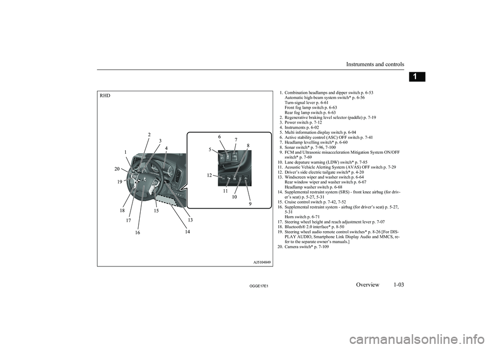
1. Combination headlamps and dipper switch p. 6-53Automatic high-beam system switch* p. 6-56
Turn-signal lever p. 6-61
Front fog lamp switch p. 6-63
Rear fog lamp switch p. 6-63
2. Regenerative braking level selector (paddle) p. 7-19
3. Power switch p. 7-12
4. Instruments p. 6-02
5. Multi information display switch p. 6-04
6. Active stability control (ASC) OFF switch p. 7-41
7. Headlamp levelling switch* p. 6-60
8. Sonar switch* p. 7-96, 7-100
9. FCM and Ultrasonic misacceleration Mitigation System ON/OFF switch* p. 7-69
10. Lane depature warning (LDW) switch* p. 7-85
11. Acoustic Vehicle Alerting System (AVAS) OFF switch p. 7-29
12. Driver’s side electric tailgate switch* p. 4-20
13. Windscreen wiper and washer switch p. 6-64 Rear window wiper and washer switch p. 6-67
Headlamp washer switch p. 6-68
14. Supplemental restraint system (SRS) - front knee airbag (for driv- er’s seat) p. 5-27, 5-31
15. Cruise control switch p. 7-42, 7-52
16. Supplemental restraint system - airbag (for driver’s seat) p. 5-27, 5-31
Horn switch p. 6-71
17. Steering wheel height and reach adjustment lever p. 7-07
18. Bluetooth® 2.0 interface* p. 8-50
19. Steering wheel audio remote control switches* p. 8-26 [For DIS- PLAY AUDIO, Smartphone Link Display Audio and MMCS, re-
fer to the separate owner’s manuals.]
20. Camera switch* p. 7-109
Instruments and controls
1-03OGGE17E1Overview1RHD
Page 7 of 548
![MITSUBISHI OUTLANDER PHEV 2017 Owners Manual (in English) 1. Audio* p. 8-14MITSUBISHI Multi-Communication System (MMCS)*
Multi Around Monitor* p. 7-106
[For DISPLAY AUDIO, Smartphone Link Display Audio and
MMCS,
refer to the separate owner’s manuals.]
2. H MITSUBISHI OUTLANDER PHEV 2017 Owners Manual (in English) 1. Audio* p. 8-14MITSUBISHI Multi-Communication System (MMCS)*
Multi Around Monitor* p. 7-106
[For DISPLAY AUDIO, Smartphone Link Display Audio and
MMCS,
refer to the separate owner’s manuals.]
2. H](/img/19/34889/w960_34889-6.png)
1. Audio* p. 8-14MITSUBISHI Multi-Communication System (MMCS)*
Multi Around Monitor* p. 7-106
[For DISPLAY AUDIO, Smartphone Link Display Audio and
MMCS,
refer to the separate owner’s manuals.]
2. Hazard warning flasher switch p. 6-62
3. ECO mode switch p. 6-62
4. Front passenger’s airbag indicator p. 5-30
5. Passenger’s ventilators p. 8-02
6. Accessory socket* p. 8-75 Cigarette lighter* p. 8-74
7. Electric tailgate power switch* p. 4-20
8. Key slot p. 7-15
9. 220-240 V AC power supply switch* p. 8-76
10. Blind Spot Warning (BSW) switch* p. 7-80
11. Heated steering wheel switch* p. 6-71
12. Heated windscreen switch* p. 6-70
13. Cup holder p. 8-83
14. Selector lever (Joystick type) p. 7-16
15. 220-240 V AC power supply* p. 8-76
16. Floor console box p. 8-82 Arm rest
Accessory socket p. 8-75
USB input terminal p. 8-70
17. Fuel tank filler door release lever p. 2-15
18. Bonnet release lever p. 11-04
19. Rear window demister switch p. 6-69 Wiper de-icer switch* p. 6-69
20. Air conditioner p. 8-04
21. Seat belt reminder p. 5-11
Instruments and controls
1-04OGGE17E1Overview1LHD
Page 8 of 548
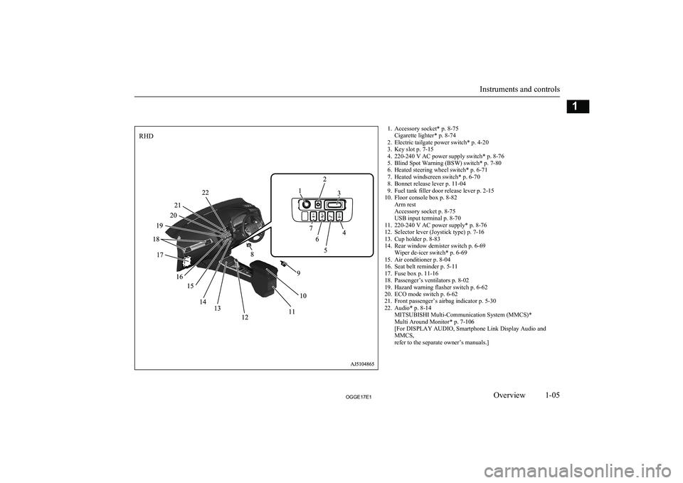
1. Accessory socket* p. 8-75Cigarette lighter* p. 8-74
2. Electric tailgate power switch* p. 4-20
3. Key slot p. 7-15
4. 220-240 V AC power supply switch* p. 8-76
5. Blind Spot Warning (BSW) switch* p. 7-80
6. Heated steering wheel switch* p. 6-71
7. Heated windscreen switch* p. 6-70
8. Bonnet release lever p. 11-04
9. Fuel tank filler door release lever p. 2-15
10. Floor console box p. 8-82 Arm rest
Accessory socket p. 8-75
USB input terminal p. 8-70
11. 220-240 V AC power supply* p. 8-76
12. Selector lever (Joystick type) p. 7-16
13. Cup holder p. 8-83
14. Rear window demister switch p. 6-69 Wiper de-icer switch* p. 6-69
15. Air conditioner p. 8-04
16. Seat belt reminder p. 5-11
17. Fuse box p. 11-16
18. Passenger’s ventilators p. 8-02
19. Hazard warning flasher switch p. 6-62
20. ECO mode switch p. 6-62
21. Front passenger’s airbag indicator p. 5-30
22. Audio* p. 8-14 MITSUBISHI Multi-Communication System (MMCS)*
Multi Around Monitor* p. 7-106
[For DISPLAY AUDIO, Smartphone Link Display Audio and
MMCS,
refer to the separate owner’s manuals.]
Instruments and controls
1-05OGGE17E1Overview1RHD
Page 13 of 548
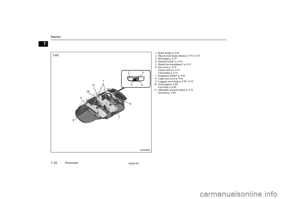
1. Bottle holder p. 8-84
2. Map & room lamps (front) p. 8-79, 11-25
3. Downlight p. 8-79
4. Sunroof switch* p. 4-36
5. Hands-free microphone* p. 8-51
6. Sun visors p. 8-73 Vanity mirror p. 8-73
Card holder p. 8-73
7. Sunglasses holder* p. 8-83
8. Cargo area cover p. 8-85
9. Luggage room lamp p. 8-80, 11-25
10. Assist grips p. 8-86 Coat hook p. 8-86
11. Adjustable seat belt anchor p. 5-12 Seat belts p. 5-09
Interior
1-10OGGE17E1Overview1LHD
Page 14 of 548
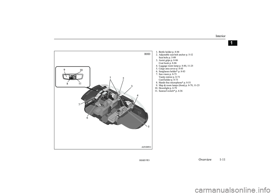
1. Bottle holder p. 8-84
2. Adjustable seat belt anchor p. 5-12 Seat belts p. 5-09
3. Assist grips p. 8-86 Coat hook p. 8-86
4. Luggage room lamp p. 8-80, 11-25
5. Cargo area cover p. 8-85
6. Sunglasses holder* p. 8-83
7. Sun visors p. 8-73 Vanity mirror p. 8-73
Card holder p. 8-73
8. Hands-free microphone* p. 8-51
9. Map & room lamps (front) p. 8-79, 11-25
10. Downlight p. 8-79
11. Sunroof switch* p. 4-36
Interior
1-11OGGE17E1Overview1RHD
Page 42 of 548
Installation of accessoriesE00200302361
We recommend you to consult your MITSUBISHI MOTORS Authorized Service
Point.CAUTIONl Your vehicle is equipped with a diagnosis
connector for checking and servicing theelectronic control system.
Do not connect a device other than a diagno-
sis tool for inspections and service to this connector. Otherwise, the auxiliary battery
could be discharged, the electronic devices
of the vehicle could malfunction, or other unexpected problems could result.
In addition, malfunctions caused by connect-
ing a device other than a diagnosis tool may not be covered under warranty.
l The installation of accessories, optional
parts, etc., should only be carried out
within the limits prescribed by law in your country, and in accordance with the
guidelines and warnings contained with-
in the documents accompanying this ve- hicle.
l Installing electric components incorrect-
ly could lead to a fire. Refer to the “Modification/alterations to the electri-
cal or fuel systems” section within this
owner’s manual.
l When installing the radio, for the re-
quired information (frequency, transmis-
sion output, installing procedure), con- sult a MITSUBISHI MOTORS Author-
ized Service Point.
If the frequency, transmission output and installing condition are not appropriate,
it can adversely affect the electronic de- vices and could lead to unsafe vehicle operation.
l Using a cellular phone or radio set inside
the vehicle without an external antenna
may cause electrical system interference,
which could lead to unsafe vehicle oper-ation.
l Tyres and wheels which do not meet
specifications must not be used.
Refer to the “Specifications” section for information regarding wheel and tyre
sizes.
Important points!
Due to large number of accessory and re- placement parts of different manufactures available in the market, it is not possible, not
only for MITSUBISHI MOTORS , but also
for a MITSUBISHI MOTORS Authorized
Service Point, to check whether the attach- ment or installation of such parts affects the
overall safety of your MITSUBISHI-vehicle.
Even when such parts are officially author-
ized, for example by a “general operators
permit” (an appraisal for the part) or through the execution of the part in an officially ap-
proved manner of construction, or when a single operation permit following the attach- ment or installation of such parts, it cannot be
deduced from that alone, that the driving safety of your vehicles has not been affected.
Consider also that there basically exists no li- ability on the part of the appraiser or the offi-
cial. Maximum safety can only be ensured
with parts recommended, sold and fitted or
installed by a MITSUBISHI MOTORS au-
thorized Service Point ( MITSUBISHI
MOTORS GENUINE replacement parts and
MITSUBISHI MOTORS accessories). The
same also pertains to modifications of
MITSUBISHI vehicles with respect to the
production specifications. For safety reasons, do not attempt any modifications other than
those that follow the recommendations of a MITSUBISHI MOTORS authorized Service
Point.
Installation of accessories
2-17OGGE17E1General information2
Page 69 of 548
For the operation method of theMITSUBISHI Remote Control, please visit
the MITSUBISHI MOTORS Web site:
http://www.mitsubishi-motors.com/en/prod-
ucts/ outlander_phev2/app/remote/
l If you need further information, please
contact a MITSUBISHI MOTORS Au-
thorized Service Point.WARNINGl Do not use the
MITSUBISHI Remote
Control if children, persons in need of care, pets, etc. are in the vehicle. Even if the remote climate control is used, thecabin may become hot or cold due to somereasons such as automatic stop of the sys-
tem. The cabin temperature may quickly
rise in sunshine, which poses a risk of heat
stroke and dehydration. In cold weather, on the other hand, the cabin temperature
may quickly drop. Either of which could lead to death in the worst case.
In addition, children can activate switches and controls, resulting in injury or a fatal
accident.
l The cooling fan in the engine compart-
ment may operate automatically when
charging or when operating air condition- er. Do not bring your hand close to the
cooling fan during charging.CAUTIONl Do not use a car cover except for the
MITSUBISHI MOTORS GENUINE car
cover, when using the charging timer or the remote climate control.NOTEl Keep the following points in mind when us-
ing a wireless LAN device:
• Communication speed and range vary de-
pending on the wireless LAN devices and the surrounding conditions (radio environ-
ment, obstacles, parking area environ- ment, etc.).
• Due to the characteristics of radio waves,
communication speed tends to decrease as the communication distance increases.
Use your wireless LAN device at a short
distance from the vehicle for better re- sponse.
• When a microwave oven or ISM (indus-
trial, scientific and medical) equipment is being used, the communication speed andrange of wireless LAN devices may de-crease. Use your wireless LAN device
away from these appliances and equip-
ment.NOTE• If a wireless LAN device and Bluetooth
(registered trademark of Bluetooth SIG, Inc.) are used simultaneously, the com-
munication speed and range of each de- vice may decrease. Use your wireless
LAN device away from Bluetooth devi- ces.
l Wireless LAN devices may not communi-
cate with the vehicle, or may not operate
normally or stably in the following environ- ment or situations. Check that the device cancommunicate with your vehicle before use.
• There is an obstruction such as a concrete
or metal wall between the vehicle and
wireless LAN device.
• The vehicle is surrounded by tall vehicles
in a parking lot.
• There are facilities nearby that emit strong
radio waves, such as a TV tower, trans-
former substation, broadcasting station or airport.
• There is a communication device such as
a mobile phone or radio, or an electric de- vice such as a personal computer near thewireless LAN device.
• The wireless LAN device is in contact
with or covered by a metal object.
• The battery of the wireless LAN device
has run down.
l The
MITSUBISHI Remote Control cannot
be used under the following conditions:
• The wireless LAN device is turned off.
MITSUBISHI Remote Control*
3-26OGGE17E1Charging3
Page 73 of 548
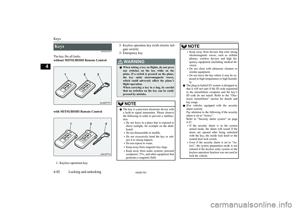
KeysE00300103817
The key fits all locks.
without MITSUBISHI Remote Control
with MITSUBISHI Remote Control
1- Keyless operation key
2- Keyless operation key (with electric tail-
gate switch)
3- Emergency keyWARNINGl When taking a key on flights, do not press
any switches on the key while on the plane. If a switch is pressed on the plane,
the key emits electromagnetic waves, which could adversely affect the plane’s flight operation.
When carrying a key in a bag, be careful that no switches on the key can be easily
pressed by mistake.NOTEl The key is a precision electronic device with
a built-in signal transmitter. Please observe
the following in order to prevent a malfunc- tion.
• Do not leave in a place that is exposed to
direct sunlight, for example on the dash- board.
• Do not disassemble or modify.
• Do not excessively bend the key or sub-
ject it to strong impacts.
• Do not expose to water.
• Keep away from magnetic key rings.
• Keep away from audio systems, personal
computers, TVs, and other equipment that generates a magnetic field.NOTE• Keep away from devices that emit strong
electromagnetic waves, such as cellular
phones, wireless devices and high fre- quency equipment (including medical de-
vices).
• Do not clean with ultrasonic cleaners or
similar equipment.
• Do not leave the key where it may be ex-
posed to high temperature or high humidi- ty.
l The plug-in hybrid EV system is designed so
that it will not start if the ID code registered
in the immobilizer computer and the key’s ID code do not match. Refer to the “Elec-
tronic immobilizer” section for details and key usage.
l [For vehicles equipped with the security
alarm system]
Pay attention to the following if the security
alarm is set to “Active”.
Refer to “Security alarm system” on page 4-27.
• If the security alarm is in the system
armed mode, the alarm will sound if the
doors are opened after being unlocked with the key, the inside lock knob or the
central door lock switch.
• Even if the security alarm is set to “Ac-
tive”, the system preparation mode is not entered if the keyless entry system or thekeyless operation function was not used to
lock the vehicle.
Keys
4-02OGGE17E1Locking and unlocking4
Page 75 of 548
To lock
Press the LOCK switch (1). All the doors andthe tailgate will be locked. The turn-signal
lamps will blink once when the doors and the
tailgate are locked.
To unlock
Press the UNLOCK switch (2). All the doors
and the tailgate will be unlocked. If the doors and tailgate are unlocked when the frontroom lamp switch is in the “DOOR” positionor the rear room lamp switch is in the middle
(•) position, the room lamp will illuminate for
approximately 15 seconds and the turn-signal lamps will blink twice.
The position and tail lamps can also be set to
turn on for approximately 30 seconds. Refer to “Instruments and controls: Welcome light”
on page 6-59.
NOTEl For the operation of the Electric tailgate
switch (3), refer to “Electric tailgate” onpage 4-20.
l For the operation of the Charging timer can-
cel switch (5), refer to “MITSUBISHI Re-
mote Control” on page 3-24.NOTEl The door and tailgate unlock function can be
set so that only the driver’s door unlocks
when the UNLOCK switch (2) is pressed once.
If the door and tailgate unlock function is set
to work as described above, all the doors and
the tailgate unlock when the UNLOCK switch is pressed two times in succession.
Refer to “Setting of door and tailgate unlock
function” on page 4-05.
l If the UNLOCK switch (2) is pressed and no
door or tailgate is opened within approxi-mately 30 seconds, relocking will automati-
cally occur.
l If either of the following problems occurs,
the battery may be exhausted.
• The remote control switch is operated at
the correct distance from the vehicle, but
the doors and tailgate are not locked/
unlocked in response.
• The indication lamp (4) is dim or does not
come on.
For further information, please consult your MITSUBISHI MOTORS Authorized
Service Point.
If you replace the battery yourself, refer to
“Procedure for replacing the remote con-
trol switch battery” on page 4-06.
l It is possible to modify functions as follows:
For further information, please contact your MITSUBISHI MOTORS Authorized Serv-
ice Point.
On vehicles equipped with the Smartphone Link Display Audio or the MITSUBISHINOTEMulti-Communication System (MMCS),
screen operations can be used to make theadjustment. Refer to the separate owner’s
manual for details.
• The time for automatic relocking can be
changed.
• The confirmation function (flashing of the
turn-signal lamps) can be set to operateonly when the doors and backdoor arelocked or only when the doors and back-
door are unlocked.
• The confirmation function (this indicates
locking or unlocking of the doors and tail-
gate with the blink of the turn-signal lamps) can be deactivated.
• The number of times the turn-signal
lamps are flashed by the confirmation function can be changed.Operation of the outside rear-
view mirrors (Vehicles equip- ped with mirror retractorswitch)
E00310801581
To fold
Within 30 seconds of locking the doors and tailgate using the LOCK switch (1), press the LOCK switch twice rapidly to fold the out-
side rear-view mirrors.
Keyless entry system
4-04OGGE17E1Locking and unlocking4