seat adjustment MITSUBISHI OUTLANDER PHEV 2017 Owner's Manual (in English)
[x] Cancel search | Manufacturer: MITSUBISHI, Model Year: 2017, Model line: OUTLANDER PHEV, Model: MITSUBISHI OUTLANDER PHEV 2017Pages: 548, PDF Size: 25.5 MB
Page 5 of 548
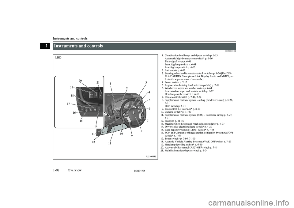
Instruments and controlsE085001018821. Combination headlamps and dipper switch p. 6-53Automatic high-beam system switch* p. 6-56
Turn-signal lever p. 6-61
Front fog lamp switch p. 6-63
Rear fog lamp switch p. 6-63
2. Instruments p. 6-02
3. Steering wheel audio remote control switches p. 8-26 [For DIS- PLAY AUDIO, Smartphone Link Display Audio and MMCS, re-
fer to the separate owner’s manuals.]
4. Power switch p. 7-12
5. Regenerative braking level selector (paddle) p. 7-19
6. Windscreen wiper and washer switch p. 6-64 Rear window wiper and washer switch p. 6-67
Headlamp washer switch p. 6-68
7. Cruise control switch p. 7-42, 7-52
8. Supplemental restraint system - airbag (for driver’s seat) p. 5-27, 5-31
Horn switch p. 6-71
9. Bluetooth® 2.0 interface* p. 8-50
10. Camera switch* p. 7-109
11. Supplemental restraint system (SRS) - front knee airbag p. 5-27, 5-31
12. Fuse box p. 11-16
13. Steering wheel height and reach adjustment lever p. 7-07
14. Driver’s side electric tailgate switch* p. 4-20
15. Lane depature warning (LDW) switch* p. 7-85
16. FCM and Ultrasonic misacceleration Mitigation System ON/OFF switch* p. 7-69
17. Sonar switch* p. 7-96, 7-100
18. Acoustic Vehicle Alerting System (AVAS) OFF switch p. 7-29
19. Headlamp levelling switch* p. 6-60
20. Active stability control (ASC) OFF switch p. 7-41
21. Multi information display switch p. 6-04
Instruments and controls
1-02OGGE17E1Overview1LHD
Page 6 of 548
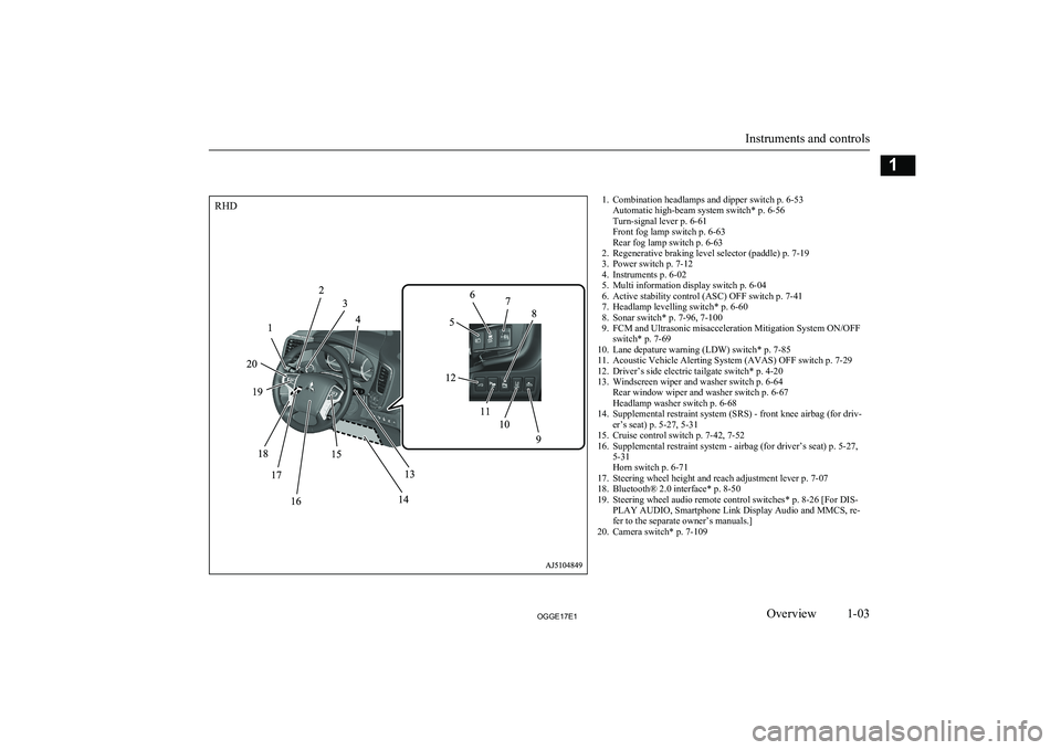
1. Combination headlamps and dipper switch p. 6-53Automatic high-beam system switch* p. 6-56
Turn-signal lever p. 6-61
Front fog lamp switch p. 6-63
Rear fog lamp switch p. 6-63
2. Regenerative braking level selector (paddle) p. 7-19
3. Power switch p. 7-12
4. Instruments p. 6-02
5. Multi information display switch p. 6-04
6. Active stability control (ASC) OFF switch p. 7-41
7. Headlamp levelling switch* p. 6-60
8. Sonar switch* p. 7-96, 7-100
9. FCM and Ultrasonic misacceleration Mitigation System ON/OFF switch* p. 7-69
10. Lane depature warning (LDW) switch* p. 7-85
11. Acoustic Vehicle Alerting System (AVAS) OFF switch p. 7-29
12. Driver’s side electric tailgate switch* p. 4-20
13. Windscreen wiper and washer switch p. 6-64 Rear window wiper and washer switch p. 6-67
Headlamp washer switch p. 6-68
14. Supplemental restraint system (SRS) - front knee airbag (for driv- er’s seat) p. 5-27, 5-31
15. Cruise control switch p. 7-42, 7-52
16. Supplemental restraint system - airbag (for driver’s seat) p. 5-27, 5-31
Horn switch p. 6-71
17. Steering wheel height and reach adjustment lever p. 7-07
18. Bluetooth® 2.0 interface* p. 8-50
19. Steering wheel audio remote control switches* p. 8-26 [For DIS- PLAY AUDIO, Smartphone Link Display Audio and MMCS, re-
fer to the separate owner’s manuals.]
20. Camera switch* p. 7-109
Instruments and controls
1-03OGGE17E1Overview1RHD
Page 19 of 548
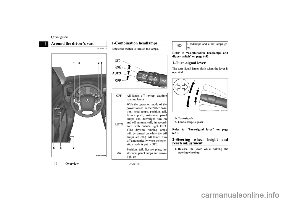
Around the driver’s seat
E08500801557
1-Combination headlamps
Rotate the switch to turn on the lamps.
OFFAll lamps off {except daytimerunning lamps}
AUTO
With the operation mode of the
power switch in the “ON” posi- tion, head-lamps, position, tail,
licence plate, instrument panel lamps and downlight turn on and off automatically in accord-
ance with outside light level. {The daytime running lamps
will be turned on while the tail lamps are off.} All lamps turn
off automatically when the oper- ation mode is put in OFF.Position, tail, licence plate, in-
strument panel lamps and down- light onHeadlamps and other lamps go
on
Refer to “Combination headlamps and dipper switch” on page 6-53.
1-Turn-signal lever
The turn-signal lamps flash when the lever is
operated
1- Turn-signals
2- Lane-change signals
Refer to “Turn-signal lever” on page 6-61.
2-Steering wheel height and
reach adjustment
1. Release the lever while holding the
steering wheel up.
Quick guide
1-16OGGE17E1Overview1
Page 110 of 548
Seat arrangement................................................................................. 5-02
Seat adjustment................................................................................... 5-02 Front seats........................................................................................... 5-03
Rear seats............................................................................................ 5-05
Head restraints.....................................................................................5-05
Making a luggage area........................................................................ 5-07
Making a flat seat................................................................................ 5-08
Seat belts............................................................................................. 5-09 Pregnant women restraint....................................................................5-15
Seat belt pretensioner system and force limiter system...................... 5-15
Child restraint......................................................................................5-16 Seat belt inspection............................................................................. 5-26Supplemental restraint system (SRS)-airbag...................................... 5-27Seats and seat belts
OGGE17E15
Page 111 of 548
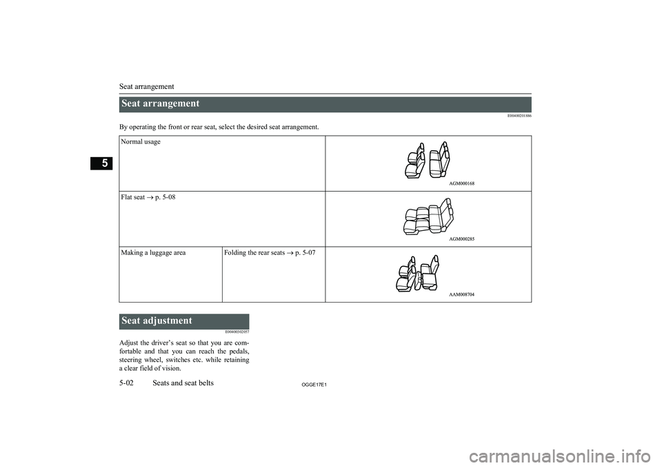
Seat arrangementE00400201886
By operating the front or rear seat, select the desired seat arrangement.Normal usageFlat seat ® p. 5-08Making a luggage areaFolding the rear seats ® p. 5-07
Seat adjustment
E00400302057
Adjust the driver’s seat so that you are com- fortable and that you can reach the pedals,
steering wheel, switches etc. while retaining a clear field of vision.
Seat arrangement
5-02OGGE17E1Seats and seat belts5
Page 114 of 548
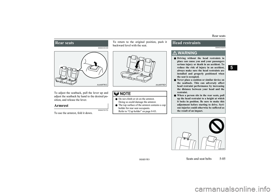
Rear seatsE00401301549
To adjust the seatback, pull the lever up andadjust the seatback by hand to the desired po-
sition, and release the lever.
Armrest
E00401701732
To use the armrest, fold it down.
To return to the original position, push it
backward level with the seat.NOTEl Do not climb or sit on the armrest.
Doing so could damage the armrest.
l The top surface of the armrest contains a cup
holder for rear seat occupants.
Refer to “Cup holder” on page 8-83.Head restraints
E00403302654WARNINGlDriving without the head restraints in
place can cause you and your passengers serious injury or death in an accident. Toreduce the risk of injury in an accident,
always make sure the head restraints are installed and properly positioned when
the seat is occupied.
l Never place a cushion or similar device on
the seatback. This can adversely affect
head restraint performance by increasing the distance between your head and the
restraint.
l When a person sits in the rear seats, pull
up the head restraint to a height at which it locks in position. Be sure to make thisadjustment before starting to drive. Seri-
ous injuries could otherwise be suffered as
the result of an impact.
Rear seats
5-05OGGE17E1Seats and seat belts5
Page 115 of 548
To adjust height
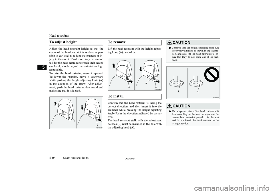
Adjust the head restraint height so that thecentre of the head restraint is as close as pos- sible to ear level to reduce the chances of in-
jury in the event of collision. Any person too
tall for the head restraint to reach their seated ear level, should adjust the restraint as highas possible.
To raise the head restraint, move it upward. To lower the restraint, move it downward while pushing the height adjusting knob (A)
in the direction of the arrow. After adjust- ment, push the head restraint downward and
make sure that it is locked.
To remove
Lift the head restraint with the height adjust-
ing knob (A) pushed in.
To install
Confirm that the head restraint is facing the
correct direction, and then insert it into the seatback while pressing the height adjusting
knob (A) in the direction indicated by the ar-
row.
The head restraint stalk with the adjustment notches (B) must be installed in the hole withthe adjusting knob (A).
CAUTIONl Confirm that the height adjusting knob (A)
is correctly adjusted as shown in the illustra- tion, and also lift the head restraints to en- sure that they do not come out of the seat-back.CAUTIONl The shape and size of the head restraint dif-
fers according to the seat. Always use the
correct head restraint provided for the seat and do not install the head restraint in the
wrong direction.
Head restraints
5-06OGGE17E1Seats and seat belts5
Page 135 of 548
NOTElIf it is difficult to latch the tether strap hook
in the rear seat, turn the hook sideways.
6. Push and pull the child restraint system in
all directions to be sure it is secure.
To remove
Remove the child restraint system in accord-ance with the instructions provided by the
child restraint system’s manufacturer.
Installing a child restraint sys-
tem to a 3-point type seat belt (with emergency locking mech-anism)
E00408701816
Installation:
1. Put a child restraint system on the seat in
which you wish to install it, and remove
the head restraint from the seat.
Refer to “Head restraints” on page 5-05.
2. When installing a child restraint system
in the front passenger seat, adjust seat slide to its most rearward position and
adjust the front seatback angle to 2 steps
rearward from the first locking position.
3. Route the belt through the child restraint
according to the child restraint system manufacturer’s instructions, then insert
the latch plate into the buckle.
4. Remove all slack of a lap belt by pulling
the webbing through the belt’s adjust-
ment feature.
3-point type seat belt requires no length adjustment, remove all slack by usingthe locking clip.
5. If your child restraint system has a sup-
port leg, make sure that there is a sup-
port leg at the stable position on the
floor.
6. Before putting the child in the restraint,
push and pull the restraint in all direc- tions to be sure it is secure. Do this be-
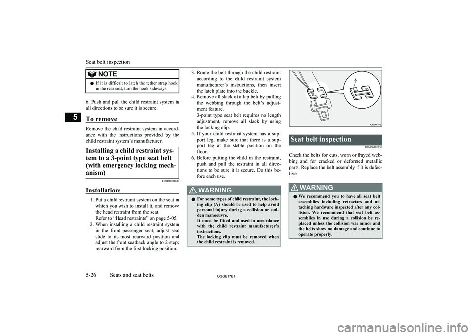
fore each use.WARNINGl For some types of child restraint, the lock-
ing clip (A) should be used to help avoid
personal injury during a collision or sud- den manoeuvre.
It must be fitted and used in accordance with the child restraint manufacturer’s
instructions.
The locking clip must be removed when the child restraint is removed.Seat belt inspection
E00406301850
Check the belts for cuts, worn or frayed web-bing and for cracked or deformed metallic
parts. Replace the belt assembly if it is defec-
tive.
WARNINGl We recommend you to have all seat belt
assemblies including retractors and at-
taching hardware inspected after any col- lision. We recommend that seat belt as-
semblies in use during a collision be re- placed unless the collision was minor and
the belts show no damage and continue to operate properly.
Seat belt inspection
5-26OGGE17E1Seats and seat belts5
Page 226 of 548
WARNINGlLeaving the engine running risks injury
or death from accidentally moving the se-
lector lever or the accumulation of toxic
exhaust fumes on the passenger compart- ment.
Where you park
WARNINGl Do not park your vehicle in areas where
combustible materials such as dry grass
or leaves can come in contact with a hot exhaust, since a fire could occur.
When leaving the vehicle
Always carry the key and lock all doors and
the tailgate when leaving the vehicle unatten-
ded.
Always try to park your vehicle in a well lit
area.
CAUTIONl When you leave the vehicle, be sure that you
have stopped the Plug-in Hybrid EV System.
The engine may start suddenly by a remain-
ing amount decline of the drive battery.Steering wheel height and
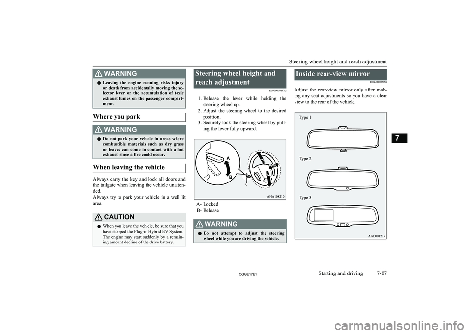
reach adjustment E00600701652
1. Release the lever while holding the
steering wheel up.
2. Adjust the steering wheel to the desired
position.
3. Securely lock the steering wheel by pull-
ing the lever fully upward.
A- Locked B- Release
WARNINGl Do not attempt to adjust the steering
wheel while you are driving the vehicle.Inside rear-view mirror
E00600802168
Adjust the rear-view mirror only after mak-
ing any seat adjustments so you have a clear
view to the rear of the vehicle.
Steering wheel height and reach adjustment
7-07OGGE17E1Starting and driving7 Type 1
Type 2
Type 3
Page 233 of 548
NOTElIt is possible to modify functions as follows:
• The time until the power cuts out can be
changed to approximately 60 minutes.
• The ACC power auto-cutout function can
be deactivated.
For details, we recommend you to consult
a MITSUBISHI MOTORS Authorized
Service Point.
On vehicles equipped with the Smart-
phone Link Display Audio or the
MITSUBISHI Multi-Communication Sys- tem (MMCS), screen operations can be used to make the adjustment.
Refer to the separate owner’s manual for
details.Operation mode OFF reminder
system
E00632201041
When the operation mode is in any mode oth- er than OFF; if you close all the doors and the tailgate, and then try to lock the doors and
tailgate by pressing the driver’s or front pas- senger’s door lock/unlock switch, or the tail-
gate LOCK switch, a warning lamp will blink or warning display will appear, and the outer
buzzer will sound preventing you from lock-
ing the doors and tailgate.Operation mode ON reminder
system
E00632301068
If the driver’s door is opened while the Plug- in Hybrid EV System is stopped and the op-
eration mode in any mode other than OFF, the operation mode ON reminder inner buz-
zer sounds intermittently to remind you to put
the operation mode in OFF.
Starting and stopping the
Plug-in Hybrid EV System E00620601295Starting the Plug-in Hybrid EV
System
E00620701661
CAUTIONl When the Plug-in Hybrid EV System warn-
ing lamp comes on while the READY indi- cator is on, avoid high-speed driving and
have your vehicle inspected by a
MITSUBISHI MOTORS Authorized Serv-
ice Point as soon as possible. (Refer to “Plug-in Hybrid EV System warning lamp” on page 6-52.)
l Never attempt to start the engine by pushing
or pulling the vehicle.
1. Check that the EV charging cable is not
connected to your vehicle.
2. Fasten the seat belt.
3. Make sure the parking brake is applied.
4. Press and hold the brake pedal down
firmly with your right foot.
5. When you press the power switch while
depressing the brake pedal, the READY indicator in the meter blinks and the acti-
vation of Plug-in Hybrid EV System
starts.
Starting and stopping the Plug-in Hybrid EV System
7-14OGGE17E1Starting and driving7