fuel cap MITSUBISHI OUTLANDER SPORT 2015 3.G Owners Manual
[x] Cancel search | Manufacturer: MITSUBISHI, Model Year: 2015, Model line: OUTLANDER SPORT, Model: MITSUBISHI OUTLANDER SPORT 2015 3.GPages: 384, PDF Size: 61.37 MB
Page 18 of 384
Filling the fuel tank
General information 3-3
3
Use of gasolines blended with MMT may adversely affect performance, and cause the malfunction indicator on your instrument panel to come on. If this happens, contact anauthorized Mitsubishi Motors dealer or a repair facility of your choice for assistance. Your vehicle may have been designed to sat- isfy California’s low-emission regulations based on clean-burning low-sulfur gasoline. Gasoline sold in parts of the country otherthan California is allowed to have a higher sulfur content. Using such gasoline could adversely affect the vehicle’s catalytic con-verter and cause the engine malfunction indi- cator (“SERVICE ENGINE SOON” or “Check engine light”) to come on. Illumina-tion of this indicator while you are using high-sulfur gasoline does not necessarily mean the vehicle’s emission-control system ismalfunctioning. Your authorized Mitsubishi Motors dealer may suggest you try using a different, lower-sulfur brand of unleaded gas-oline to determine whether the problem is fuel-related.
N00301101923
Sulfur in gasoline
NOTE
Poor-quality gasoline can cause problems such as poor starting,
stalling during idling,
abnormal engine noise, and poor accelera- tion. If you experience any of these prob- lems, try using a different brand of gasoline.If the engine malfunction indicator (“SER- VICE ENGINE SOON” or “Check engine light”) flashes, have the vehicle inspected assoon as possible by the nearest authorized Mitsubishi Motors dealer or a repair facility of your choice. Repeatedly driving short distances at low speeds can cause deposits to form in the fuelsystem and engine, resulting in poor starting and poor acceleration. If these problems occur, you are advised to add a detergentadditive to the gasoline when you refuel the vehicle. The additive will remove the depos- its, thereby returning the engine to a normalcondition. Be sure to use a Mitsubishi Motors Genuine cleaning additive. Using an unsuitable additive could make the enginemalfunction. For details, please contact the nearest authorized Mitsubishi Motors dealer.
Filling the fuel tank
WA R N I N G Gasoline is highly flammable and explo- sive. You could be burned, seriously injured or killed when handling it. When refueling your vehicle, always turn theengine off and keep away from flames, sparks, and smoking materials. Always handle fuel in well-ventilated outdoorareas. Before removing the fuel tank filler cap, be sure to get rid of your body’s static electricity by touching a metal part of the car or fuel pump. Any static electricity onyour body could create a spark that ignites fuel vapor. Perform the whole refueling process (opening the fuel tank filler door, remov- ing the fuel cap, etc.) by yourself; do notlet any other person near the fuel tank filler. If you allowed a person to help you and that person was carrying static elec-tricity, fuel vapor could be ignited. Do not move away from the fuel tank filler until refueling is finished. If you moved away and did something else (for example, sitting on a seat) part-way through the refueling process, you could pick up a fresh charge of static electricity. Be careful not to inhale fuel vapor. Fuel contains toxic substances.
BK0206700US.bo
ok 3 ページ 2014年3月25日 火曜日 午後4時42分
Page 19 of 384
Filling the fuel tank 3-4 General information
3
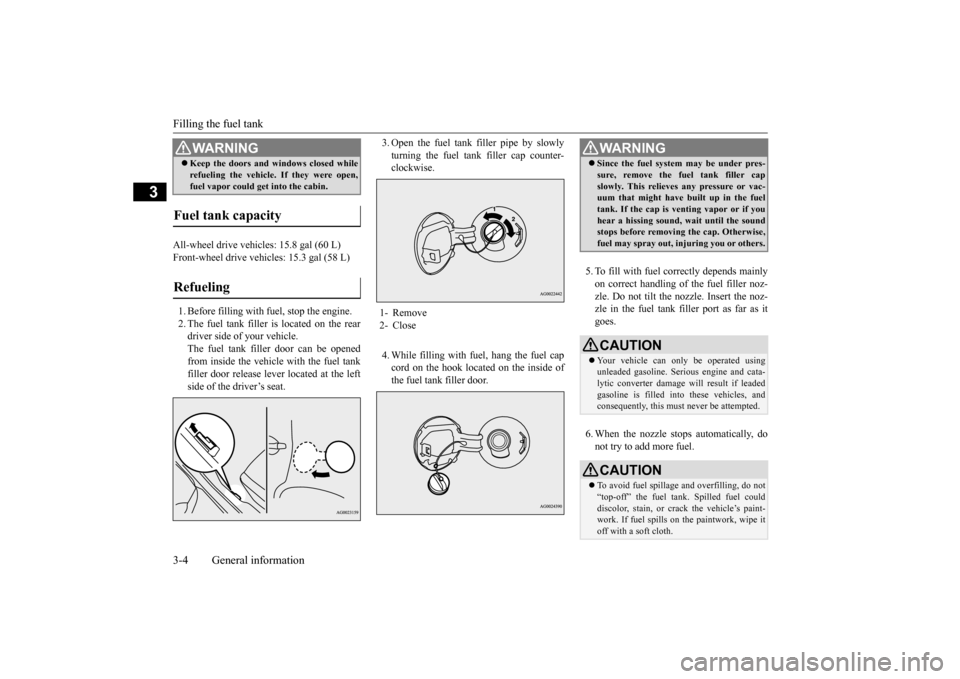
All-wheel drive vehicles: 15.8 gal (60 L) Front-wheel drive vehicles: 15.3 gal (58 L) 1. Before filling with fuel, stop the engine. 2. The fuel tank filler is located on the rear driver side of your vehicle. The fuel tank filler door can be openedfrom inside the vehicle with the fuel tank filler door release le
ver located at the left
side of the driver’s seat.
3. Open the fuel tank filler pipe by slowly turning the fuel tank filler cap counter- clockwise. 4. While filling with fuel, hang the fuel cap cord on the hook located on the inside of the fuel tank filler door.
5. To fill with fuel correctly depends mainly on correct handling of the fuel filler noz-zle. Do not tilt the nozzle. Insert the noz- zle in the fuel tank filler port as far as it goes. 6. When the nozzle stops automatically, do not try to add more fuel.
Keep the doors and windows closed while refueling the vehicle. If they were open, fuel vapor could get into the cabin.
Fuel tank capacity Refueling
WA R N I N G
1- Remove 2- Close
WA R N I N G Since the fuel system may be under pres- sure, remove the fuel tank filler cap slowly. This relieves any pressure or vac- uum that might have built up in the fuel tank. If the cap is venting vapor or if youhear a hissing sound, wait until the sound stops before removing the cap. Otherwise, fuel may spray out, injuring you or others.CAUTION Your vehicle can only be operated using unleaded gasoline. Serious engine and cata-lytic converter damage will result if leaded gasoline is filled into these vehicles, and consequently, this must never be attempted.CAUTION To avoid fuel spillage
and overfilling, do not
“top-off” the fuel tank. Spilled fuel could discolor, stain, or crack the vehicle’s paint- work. If fuel spills on the paintwork, wipe itoff with a soft cloth.
BK0206700US.bo
ok 4 ページ 2014年3月25日 火曜日 午後4時42分
Page 20 of 384
Modifications to and racing of your vehicle
General information 3-5
3
7. To close, turn the fuel tank filler pipe cap slowly clockwise until you hear clicking sounds, then gently push the fuel tank filler door closed.
N00301600149
This vehicle should not be modified withnon-Mitsubishi Motors genuine parts.Mitsubishi Motors designs and manufactures high quality vehicles
with an emphasis on
safety and durability. Modifications usingnon-Mitsubishi Motors genuine parts may affect the performance, safety and/or durabil- ity of your vehicle, and may violate applica-ble state and/or federal regulations. DAMAGE OR PERFORMANCE PROB- LEMS RESULTING FROM MODIFICA- TIONS TO OR RACING OF YOUR VEHICLE ARE NOT COVEREDUNDER WARRANTY. Examples of modifications to your vehicle that can cause damage or performance prob- lems include the following: Failure to use Mitsubishi Motors genuine parts Failure to use required fuel and fluids Failure to use proper size tires and wheels Modification of the fuel, intake, exhaust, emission, suspension, engine, drive train or electrical wiring systems
Modification of any onboard com- puter/control module, including repro- gramming, or replacing/adding chips to any onboard computer/control module
Review the Warranty and Maintenance Man- ual for further details regarding warranty cov- erage.
N00301700166
The installation of accessories, optional parts, etc., should only be carried outwithin the limits prescribed by law, and in accordance with the guidelines and warn- ings contained within the documentsaccompanying this vehicle. Only Mitsubishi Motors approved acces- sories should be fitted to your vehicle. Improper installation of electrical parts could cause fire. Refer to the “Modifica- tion/alterations to the electrical or fuelsystems” section within this owner’s man- ual.
WA R N I N G Make sure the fuel tank filler cap is securely closed. If the fuel cap were loose, fuel could leak, resulting in a fire.CAUTION If you need to replace the fuel tank filler cap, use only the cap specified for your model vehicle.NOTE
If the fuel tank filler cap
is not tight while
driving, the engine malfunction indicator (“SERVICE ENGINE SOON” or “Checkengine light”) may come on when the onboard diagnostic (OBD) system performs a self check. Always tighten the fuel tank filler cap until you hear at least 3 clicks.The indicator will go off after driving several times. If the indicator does not go off, con- tact your authorized Mitsubishi Motorsdealer or a repair f
acility of your choice as
soon as possible.
Modifications to and racing of your vehicle
Installation of accessories
CAUTION Before any electrical or electronic accesso- ries are installed, consult an authorized Mitsubishi Motors dealer.
BK0206700US.bo
ok 5 ページ 2014年3月25日 火曜日 午後4時42分
Page 66 of 384
Break-in recommendations
Features and controls 5-3
5
N00508700330
Advanced automobile manufacturing tech- niques permit you to operate your new vehi-cle without requiring a long break-in period of low-speed driving. However, you can add to the future perfor-mance and economy of your vehicle by observing the following precautions during the first 300 miles (500 km).Drive your vehicle at moderate speeds duringthe break-in period. Avoid revving the engine. Avoid rough driving such as sudden starts, sudden acceleration, prolonged high-speed driving and sudden braking. These would have a detrimental effect on the engine and also cause increased fuel andoil consumption, which could result in malfunction of the engine components. Be particularly careful to avoid full accelera-tion while in low shift position (low gears). Do not overload the vehicle. Stay within the seating capacity. (Refer to “Cargo load precautions” on page 6-10.) Do not use this vehicle for trailer towing.
N00508800562
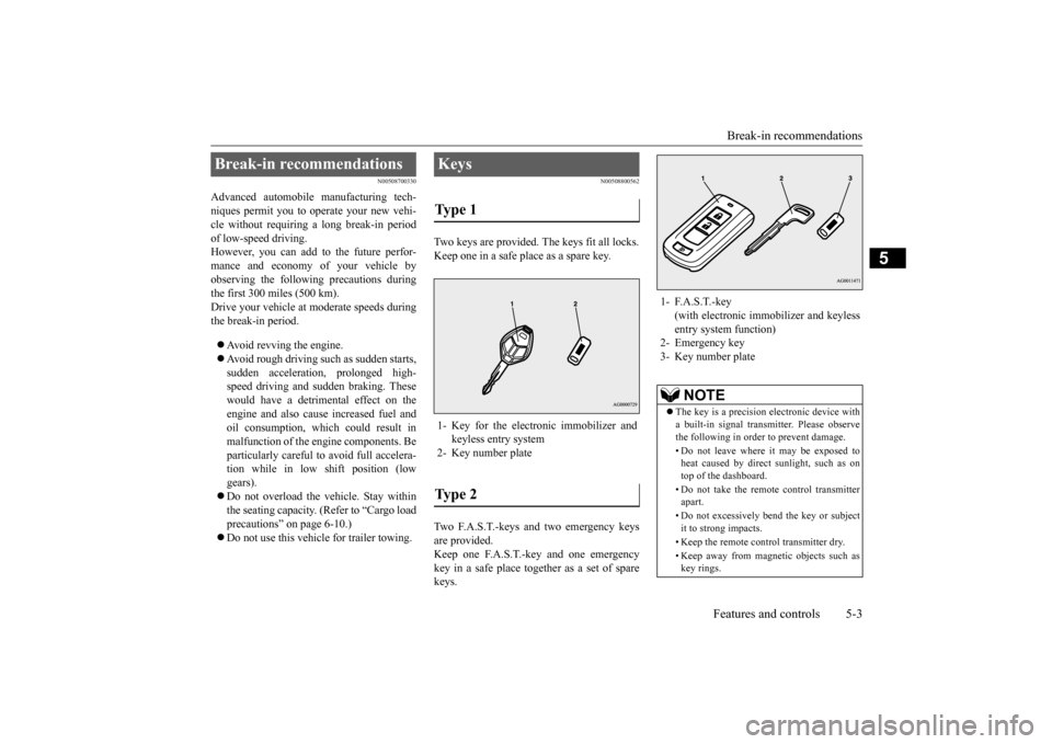
Two keys are provided. The keys fit all locks. Keep one in a safe place as a spare key. Two F.A.S.T.-keys and two emergency keys are provided. Keep one F.A.S.T.-key and one emergencykey in a safe place together as a set of spare keys.
Break-in recommendations
Keys Type 1 1- Key for the electronic immobilizer and
keyless entry system
2- Key number plateType 2
1- F.A.S.T.-key
(with electronic immob
ilizer and keyless
entry system function)
2- Emergency key 3- Key number plate
NOTE
The key is a precision electronic device with a built-in signal transmitter. Please observe the following in order to prevent damage. • Do not leave where it may be exposed to heat caused by direct sunlight, such as ontop of the dashboard. • Do not take the remote control transmitter apart. • Do not excessively bend the key or subject it to strong impacts. • Keep the remote control transmitter dry.• Keep away from magnetic objects such as key rings.
BK0206700US.bo
ok 3 ページ 2014年3月25日 火曜日 午後4時42分
Page 182 of 384
Information screen display
Features and controls 5-119
5
system. If a problem is detected in one of these systems, this indicator illuminates or flashes. When the igniti
on switch is turned to
the “ON” position or the operation mode isput in ON, this indicator normally comes on and goes off after the engine has started. This indicator will come on if the fuel tank filler cap is not properly tightened. If thisindicator comes on and stays on after refuel- ing, stop the engine and check that the cap is properly tightened. (Turn the cap clockwiseuntil you hear clicking sounds.)If this indicator does not go off after several seconds or lights up while driving, have the system checked as soon as possible at anauthorized Mitsubishi Motors dealer or a repair facility of your choice.
N00520600300
This light comes on in the event of a malfunc-tion in the charging system or when the igni-
tion switch is turned to the “ON” position (engine off) or the operation mode is put in ON. A warning is also displayed in the multi- information display. When the engine isstarted, the light should go out. Check to make sure that the light has gone out before driving.
N00558300038 N00558400143
Type 1
CAUTION Driving for a long time with the engine mal- function indicator on may cause more dam-age to the emission control system. This could also affect fuel economy and drivabil- ity. If this indicator does not come on when the ignition switch is turned to the “ON” posi- tion or the operation mode is put in ON, have the system checked at an authorizedMitsubishi Motors dealer or a repair facility of your choice.
If the engine malfunction indicator comes on while the engine is running, avoid driving at high speeds. During vehicle operation with the indicator on, the vehicle may not accelerate when youdepress the accelerator pedal. When the vehicle is stationary with the indi- cator on, you must depress the brake pedalmore firmly than usual since the engine idling speed is higher than usual and a vehi- cle with a CVT has a stronger tendency tocreep forward.NOTE
Do not disconnect the battery cable when the engine malfunction indicator (“SERVICE ENGINE SOON” or “Check engine light”) ison. The engine electronic control module stores critical OBD information (especially exhaustemission data), which may be lost if the bat- tery cable is disconnected while the engine malfunction indicator is on. This will make itdifficult to diagnose the cause of future prob- lems.
Charging system warning light
CAUTION
CAUTION If the warning light stays on while the engine is running, park your vehicle in a safe placeas soon as possible and contact an authorized Mitsubishi Motors dealer or a repair facility of your choice to have the system checked.
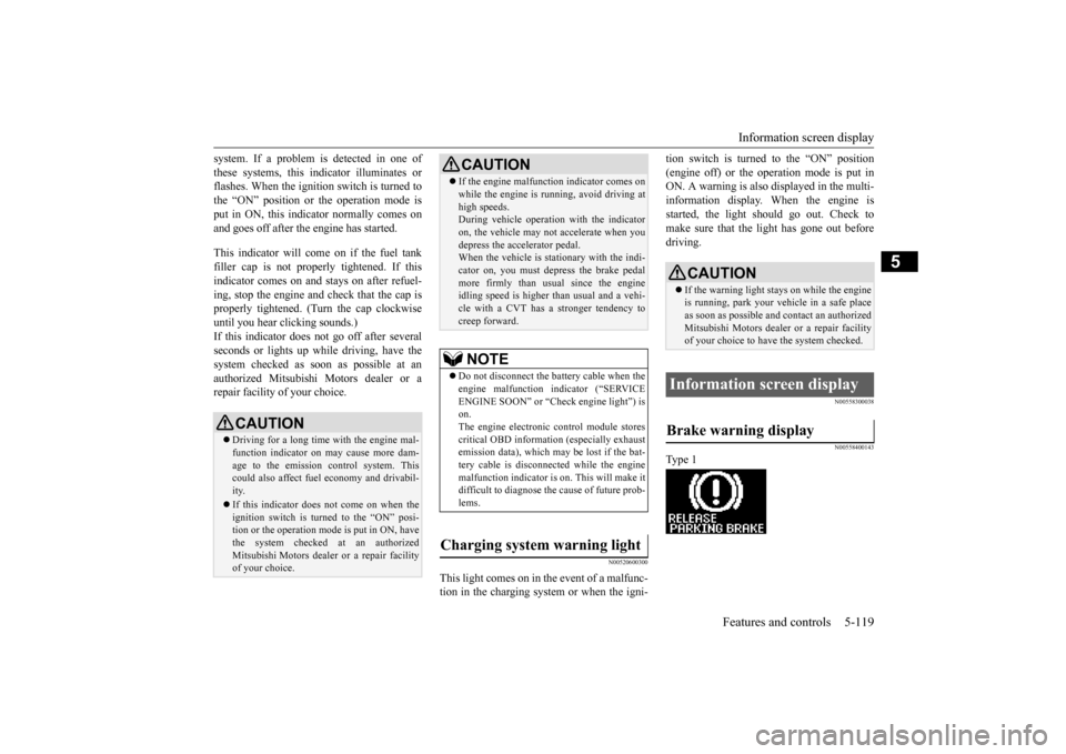
Information screen display Brake warning display
BK0206700US.book
119 ページ 2014年3月25日 火曜日 午後4時42分
Page 238 of 384
Driving during cold weather
Driving safety 6-5
6
Before changing lanes, check your mir- rors and use your turn-signal light. While driving, watch the behavior of other drivers, bicyclists, and pedestrians. Always obey applicable laws and regula- tions. Be a polite and alert driver. Always leave room for unexpected events, such assudden braking. If you plan to drive in another country, obey their vehicle registration laws andmake sure you will be able to get the rightfuel.
N00629400461
Check the battery. At the same time, check the terminals and wiring. Duringextremely cold weather, the battery will not be as strong. Also, the battery power level may drop because more power isused for cold starting and driving. Before driving the vehicle, check to see if the engine runs at the proper speed and ifthe headlights are as bright as normally.Charge or replace the battery if necessary. During extreme cold weather, it is possi- ble that a very low battery could freeze. Warm the engine sufficiently. After start- ing the engine, allow a short warm-up time to distribute oil to all cylinders. Then drive your vehicle slowly. Stay at low speeds at first so that the transaxle, transfer case and rear axle oil have time to spread to all the lubricationpoints.
Manual transaxle can be harder to shift in cold weather conditions. This is normal and shifting will get easier as the transaxle warms up. Check the engine antifreeze. If there is not enough coolant because of a leak or from engine overheating, addMitsubishi Motors Genuine Super Long Life Coolant Premium or equivalent. Please read this section in conjunctionwith the “Engine coolant” on page 9-7.
N00629500491
All the parts of the brake system are criticalto safety. Have the vehicle serviced by anauthorized Mitsubishi Motors dealer or a repair facility of your choice at regular inter- vals according to the “WARRANTY ANDMAINTENANCE MANUAL”. Check the brake system while driving at a low speed immediately after starting, espe-
Driving during cold weather
WA R N I N G The battery gives off explosive hydrogen gas. Any spark or flame can cause the bat-tery to explode, which could cause serious injury or death. Always wear protective clothes and a facemask when working with your battery, or let a skilled mechanic do it.
WA R N I N G Never open the radiator cap when the radiator is hot. You could be seriouslyburned.
Braking When brakes are wet
BK0206700US.bo
ok 5 ページ 2014年3月25日 火曜日 午後4時42分
Page 240 of 384
Loading information Driving safety 6-7
6
More effort could be required to turn the steering wheel.Refer to “Electric power steering system (EPS)” on page 5-67. Always remove the key from the ignition switch and lock all doors and the liftgate when leaving the vehicle unattended.Always try to park your vehicle in a well lit area.
N00629900408
It is very importan
t to know how much
weight your vehicle can carry. This weight is called the vehicle capacity weight andincludes the weight of all occupants, cargo (including the roof load), non-factory-
installed options, if any, being towed. The tire and loading information placard located on the driver’s door sill of your vehicle will show how much weight it may properly carry. It is important to fami
liarize yourself with the
following terms before loading your vehicle: Vehicle maximum load on the tire: load on an individual tire that is determined by distributing to each axle its share of the maximum loaded vehicle weight anddividing by two. Vehicle normal load on the tire: load on an individual tire that is determined by dis-tributing to each axle its share of the curb weight, accessory weight, and normal occupant weight and dividing by two. Maximum loaded vehicle weight: the sum of - (a) Curb weight;(b) Accessory weight; (c) Vehicle capacity weight; and (d) Production options weight.
Curb weight: the weight of a motor vehi- cle with standard equipment including the maximum capacity of fuel, oil, and cool- ant. Accessory weight: the combined weight (in excess of those standard items which may be replaced) of automatic transmis-sion, power steering, power brakes, power windows, power seats, radio, and heater, to the extent that these items are availableas factory- installed equipment (whetherinstalled or not). Vehicle capacity weight: the rated cargo and luggage load plus 150 lbs (68 kg)
*
times the vehicle’s designated seating capacity. Production options weight: the combined weight of those installed regular produc- tion options weighing over 5 lbs (2.3 kg) in excess of those standard items whichthey replace, not previously considered in curb weight or accessory weight, includ- ing heavy duty brakes, ride levelers, roofrack, heavy duty battery, and special trim. Normal occupant weight: 150 lbs (68 kg)
* times the number of specified
occupants. (In your vehicle the number is 3)
WA R N I N G Do not park your vehicle in areas where combustible materials such as dry grass or leaves can come in contact with a hot exhaust, since a fire could occur.
Do not keep the steering wheel fully turned for a long time When leaving the vehicle Loading information
WA R N I N G Never overload your vehicle. Overloading can damage your vehicle, adversely affectvehicle performance, including handling and braking, cause tire failure, and result in an accident.
BK0206700US.bo
ok 7 ページ 2014年3月25日 火曜日 午後4時42分
Page 341 of 384
Tires 9-18 Vehicle care and maintenance
9
Cold inflation pressure must not go above the maximum values molded into the tire side- wall. After driving several miles, your tire inflation pressure may increase 2 to 6 psi (14to 41 kPa) from the cold inflation pressure. Do not let air out of the tires to get back to the specified cold pressure, or your tires will betoo low. Check your tires each time you refuel. If one tire looks lower than the others, check thepressure for all of them.You should also take the following safety pre- cautions: Keep your tires inflated to the recom- mended pressures. (See the tire and load-ing information placard attached to the driver’s door sill.) Stay within the recommended load limits. Make sure that the weight of any load in your vehicle is evenly distributed. Drive at safe speeds. After filling your tires to the correct pres- sure, check them for damage and air leaks. Be sure to reinstall the caps on thevalve stems.
N00939600241 N00939700141
The following maintenance steps are recom- mended:
Check tire pressures regularly. Have regular maintenance done on the wheel balance and front and rear suspen- sion alignment. Rotate your tires regularly as described in the “Tire rotation” section on page 9-19.
N00939800184
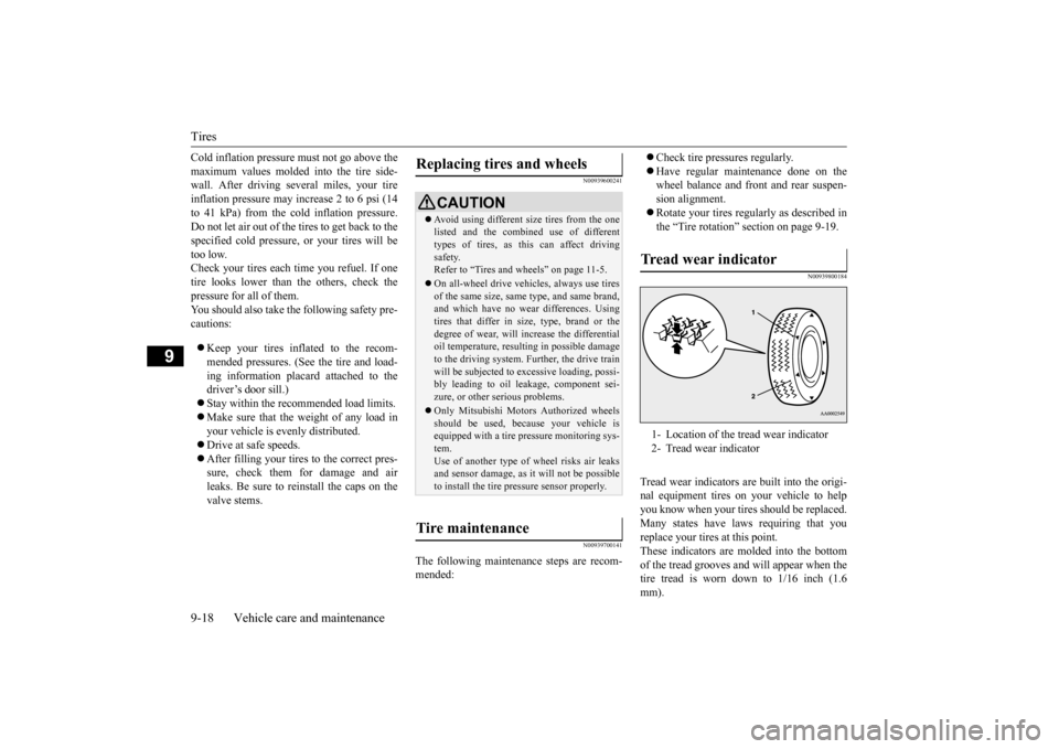
Tread wear indicators are built into the origi- nal equipment tires on your vehicle to helpyou know when your tires should be replaced. Many states have laws requiring that you replace your tires at this point.These indicators are molded into the bottom of the tread grooves and will appear when the tire tread is worn down to 1/16 inch (1.6mm).
Replacing tires and wheels
CAUTION Avoid using different
size tires from the one
listed and the combined use of different types of tires, as this can affect driving safety.Refer to “Tires and wheels” on page 11-5. On all-wheel drive vehicles, always use tires of the same size, same type, and same brand, and which have no wear differences. Using tires that differ in size, type, brand or thedegree of wear, will increase the differential oil temperature, resulting in possible damage to the driving system. Further, the drive trainwill be subjected to excessive loading, possi- bly leading to oil leakage, component sei- zure, or other serious problems. Only Mitsubishi Motors Authorized wheels should be used, because your vehicle isequipped with a tire pressure monitoring sys- tem. Use of another type of wheel risks air leaksand sensor damage, as it will not be possible to install the tire pressure sensor properly.
Tire maintenance
Tr e a d w e a r i n d i c a t o r 1- Location of the tread wear indicator 2- Tread wear indicator
BK0206700US.bo
ok 18 ページ 2014年3月25日 火曜日 午後4時42分
Page 345 of 384
General maintenance 9-22 Vehicle care and maintenance
9
N00940900228
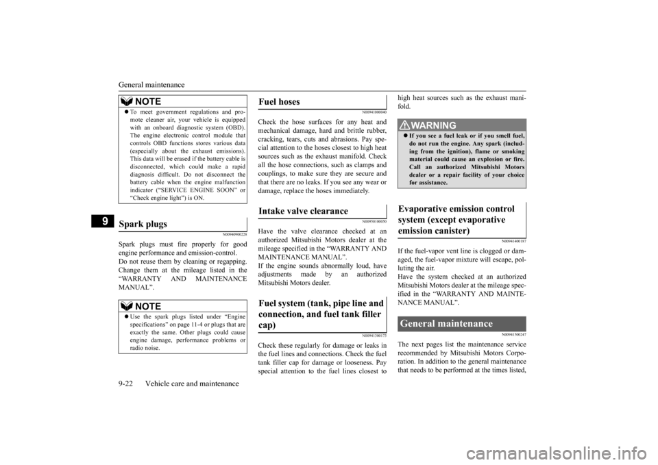
Spark plugs must fire properly for good engine performance and emission-control.Do not reuse them by cleaning or regapping. Change them at the mileage listed in the “WARRANTY AND MAINTENANCEMANUAL”.
N00941000040
Check the hose surfaces for any heat andmechanical damage, hard and brittle rubber,cracking, tears, cuts and abrasions. Pay spe- cial attention to the hoses closest to high heat sources such as the exhaust manifold. Checkall the hose connections, such as clamps and couplings, to make sure they are secure and that there are no leaks. If you see any wear ordamage, replace the hoses immediately.
N00950100050
Have the valve clearance checked at anauthorized Mitsubishi Motors dealer at themileage specified in the “WARRANTY AND MAINTENANCE MANUAL”. If the engine sounds abnormally loud, haveadjustments made by an authorized Mitsubishi Motors dealer.
N00941300173
Check these regularly for damage or leaks in the fuel lines and connections. Check the fuel tank filler cap for damage or looseness. Pay special attention to the fuel lines closest to
high heat sources such as the exhaust mani- fold.
N00941400187
If the fuel-vapor vent line is clogged or dam- aged, the fuel-vapor mixture will escape, pol- luting the air.Have the system checked at an authorized Mitsubishi Motors dealer at the mileage spec- ified in the “WARRANTY AND MAINTE-NANCE MANUAL”.
N00941500247
The next pages list the maintenance servicerecommended by Mitsubishi Motors Corpo- ration. In addition to the general maintenance that needs to be performed at the times listed,
NOTE
To meet government regulations and pro- mote cleaner air, your vehicle is equipped with an onboard diagnostic system (OBD). The engine electronic control module that controls OBD functions stores various data(especially about the exhaust emissions). This data will be erased if the battery cable is disconnected, which could make a rapiddiagnosis difficult. Do not disconnect the battery cable when the engine malfunction indicator (“SERVICE ENGINE SOON” or“Check engine light”) is ON.
Spark plugs
NOTE
Use the spark plugs listed under “Engine specifications” on page 11-4 or plugs that are exactly the same. Other plugs could causeengine damage, performance problems or radio noise.
Fuel hoses Intake valve clearance Fuel system (tank, pipe line and connection, and fuel tank filler cap)
WA R N I N G If you see a fuel leak or if you smell fuel, do not run the engine. Any spark (includ- ing from the ignition), flame or smokingmaterial could cause an explosion or fire. Call an authorized Mitsubishi Motors dealer or a repair facility of your choicefor assistance.
Evaporative emission control system (except evaporative emission canister) General maintenance
BK0206700US.bo
ok 22 ページ 2014年3月25日 火曜日 午後4時42分
Page 350 of 384
Fuses
Vehicle care and maintenance 9-27
9
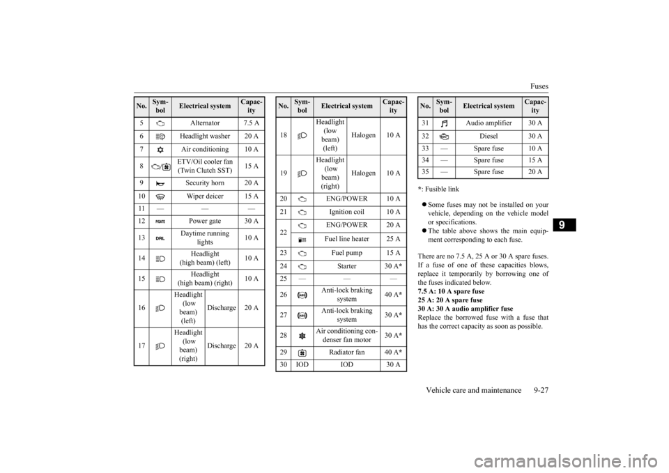
* : Fusible link Some fuses may not be installed on your vehicle, depending on the vehicle model or specifications. The table above shows the main equip- ment corresponding to each fuse.
There are no 7.5 A, 25 A or 30 A spare fuses. If a fuse of one of these capacities blows,replace it temporarily by borrowing one ofthe fuses indicated below. 7.5 A: 10 A spare fuse 25 A: 20 A spare fuse30 A: 30 A audio amplifier fuse Replace the borrowed fuse with a fuse that has the correct capacity as soon as possible.
5 Alternator 7.5 A 6 Headlight washer 20 A 7 Air conditioning 10 A 8
ETV/Oil cooler fan (Twin Clutch SST)
15 A
9 Security horn 20 A 10 Wiper deicer 15 A 11 — — — 12 Power gate 30 A 13
Daytime running
lights
10 A
14
Headlight
(high beam) (left)
10 A
15
Headlight
(high beam) (right)
10 A
16
Headlight (low beam) (left)
Discharge 20 A
17
Headlight (low beam) (right)
Discharge 20 A
No.
Sym- bol
Electrical system
Capac-ity
18
Headlight (low beam) (left)
Halogen 10 A
19
Headlight (low beam) (right)
Halogen 10 A
20 ENG/POWER 10 A 21 Ignition coil 10 A 22
ENG/POWER 20 A Fuel line heater 25 A
23 Fuel pump 15 A 24 Starter 30 A
*
25 — — — 26
Anti-lock braking
system
40 A
*
27
Anti-lock braking
system
30 A
*
28
Air conditioning con- denser fan motor
30 A
*
29 Radiator fan 40 A
*
30 IOD IOD 30 ANo.
Sym- bol
Electrical system
Capac-ity
31 Audio amplifier 30 A 32 Diesel 30 A 33 — Spare fuse 10 A 34 — Spare fuse 15 A35 — Spare fuse 20 ANo.
Sym- bol
Electrical system
Capac-ity
BK0206700US.bo
ok 27 ページ 2014年3月25日 火曜日 午後4時42分