towing MITSUBISHI PAJERO IV 2011 Owners Manual
[x] Cancel search | Manufacturer: MITSUBISHI, Model Year: 2011, Model line: PAJERO IV, Model: MITSUBISHI PAJERO IV 2011Pages: 377, PDF Size: 29.43 MB
Page 51 of 377
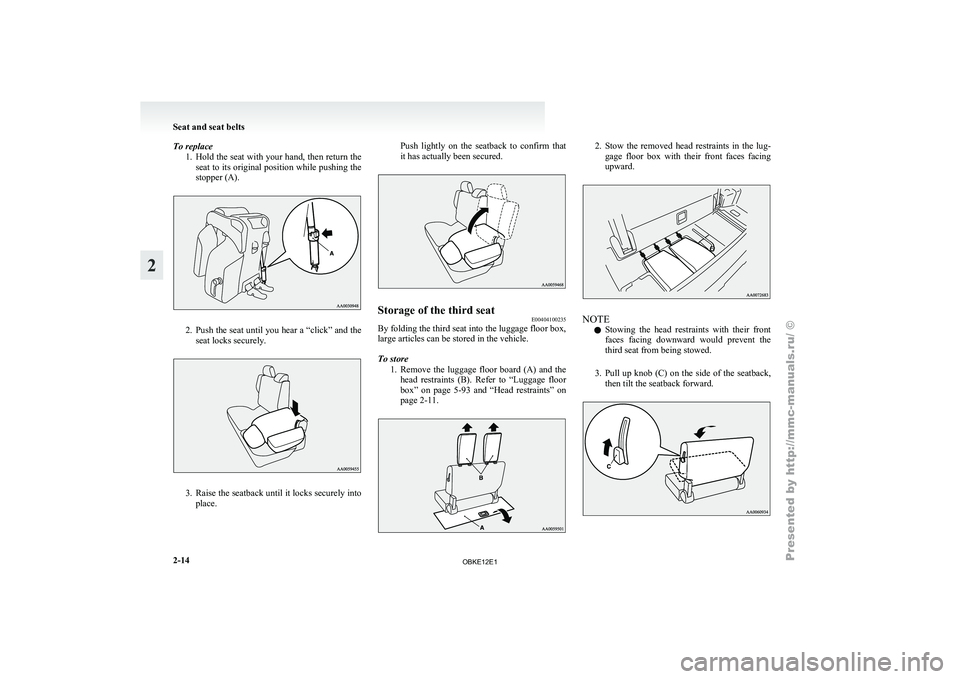
To replace
1. Hold the seat with your hand, then return the
seat to its original position while pushing the
stopper (A). 2. Push the seat until you hear a “click” and the
seat locks securely. 3. Raise the seatback until it locks securely into
place. Push
lightly
on the seatback to confirm that
it has actually been secured. Storage of the third seat
E00404100235
By folding the third seat into the luggage floor box,
large articles can be stored in the vehicle.
To store
1. Remove the luggage
floor board (A) and the
head restraints (B). Refer to “Luggage floor
box” on page 5-93 and “Head restraints” on
page 2-11. 2. Stow the removed head restraints in the lug-
gage floor
box with their front faces facing
upward. NOTE
l Stowing
the head
restraints with their front
faces facing downward would prevent the
third seat from being stowed.
3. Pull up knob (C) on the side of the seatback, then tilt the seatback forward. Seat and seat belts
2-14
2
OBKE12E1
Page 91 of 377
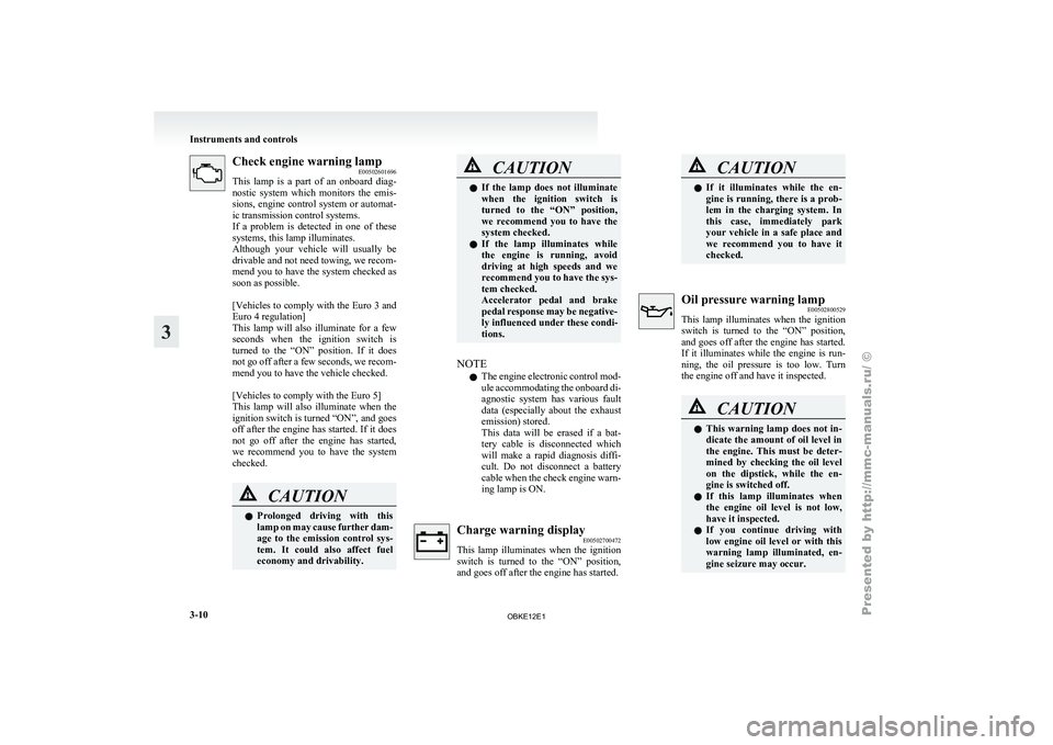
Check engine warning lamp
E00502601696
This lamp is
a part of an onboard diag-
nostic system which monitors the emis-
sions, engine control system or automat-
ic transmission control systems.
If a problem is detected in one of these
systems, this lamp illuminates.
Although your vehicle will usually be
drivable and not need towing, we recom-
mend you to have the system checked as
soon as possible.
[Vehicles to comply with the Euro 3 and
Euro 4 regulation]
This lamp will also illuminate for a few
seconds when the ignition switch is
turned to the “ON” position. If it does
not go off after a few seconds, we recom-
mend you to have the vehicle checked.
[Vehicles to comply with the Euro 5]
This lamp will also illuminate when the
ignition switch is turned “ON”, and goes
off after the engine has started. If it does
not go off after the engine has started,
we recommend you to have the system
checked. CAUTION
l
Prolonged driving
with
this
lamp on may cause further dam-
age to the emission control sys-
tem. It could also affect fuel
economy and drivability. CAUTION
l
If the lamp
does not illuminate
when the ignition switch is
turned to the “ON” position,
we recommend you to have the
system checked.
l If the lamp illuminates while
the engine is running, avoid
driving at high speeds and we
recommend you to have the sys-
tem checked.
Accelerator pedal and brake
pedal response may be negative-
ly influenced under these condi-
tions.
NOTE l The
engine electronic
control mod-
ule accommodating the onboard di-
agnostic system has various fault
data (especially about the exhaust
emission) stored.
This data will be erased if a bat-
tery cable is disconnected which
will make a rapid diagnosis diffi-
cult. Do not disconnect a battery
cable when the check engine warn-
ing lamp is ON. Charge warning display
E00502700472
This lamp illuminates
when the ignition
switch is turned to the “ON” position,
and goes off after the engine has started. CAUTION
l
If it illuminates
while the en-
gine is running, there is a prob-
lem in the charging system. In
this case, immediately park
your vehicle in a safe place and
we recommend you to have it
checked. Oil pressure warning lamp
E00502800529
This lamp illuminates
when the ignition
switch is turned to the “ON” position,
and goes off after the engine has started.
If it illuminates while the engine is run-
ning, the oil pressure is too low. Turn
the engine off and have it inspected. CAUTION
l
This warning
lamp
does not in-
dicate the amount of oil level in
the engine. This must be deter-
mined by checking the oil level
on the dipstick, while the en-
gine is switched off.
l If this lamp illuminates when
the engine oil level is not low,
have it inspected.
l If you continue driving with
low engine oil level or with this
warning lamp illuminated, en-
gine seizure may occur. Instruments and controls
3-10
3
OBKE12E1
Page 126 of 377
Economical driving.......................................................................4-02
Driving, alcohol and drugs
........................................................... 4-02
Safe driving techniques ................................................................ 4-03
Running-in recommendations....................................................... 4-04
Parking brake
................................................................................ 4-06
Parking.......................................................................................... 4-07
Steering wheel height adjustment .................................................4-08
Inside rear-view mirror ................................................................. 4-08
Outside rear-view mirrors ............................................................. 4-10
Ignition switch .............................................................................. 4-12
Steering wheel lock ...................................................................... 4-13
Starting.......................................................................................... 4-14
Diesel particulate filter (DPF)* .................................................... 4-15
Manual transmission ..................................................................... 4-16
Automatic transmission INVECS-II Sports Mode 5A/T (Intelligent & Innovative Vehicle Electronic Control
System II)................................................................................. 4-19
Super select 4WD II (SS4 II)........................................................ 4-24
Rear differential lock* .................................................................. 4-29
4-wheel drive operation ................................................................ 4-32
Inspection and maintenance following rough road oper- ation.......................................................................................... 4-35
Cautions on handling of 4-wheel drive vehicles ..........................4-35
Braking......................................................................................... 4-37
Brake assist system....................................................................... 4-38
Anti-lock brake system (ABS) ..................................................... 4-39
Power steering system.................................................................. 4-41
Active stability & traction control (ASTC) ..................................4-41
Cruise control* ............................................................................. 4-45
Reversing sensor system*............................................................. 4-49 Rear-view camera*
....................................................................... 4-52
Cargo loads................................................................................... 4-56
Trailer towing ............................................................................... 4-57Starting and driving
4
OBKE12E1
Page 129 of 377
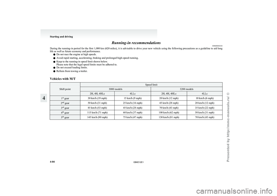
Running-in recommendations
E00600402324
During the running-in
period for the first 1,000 km (620 miles), it is advisable to drive your new vehicle using the following precautions as a guideline to aid long
life as well as future economy and performance.
l Do not race the engine at high speeds.
l Avoid rapid starting, accelerating, braking and prolonged high-speed running.
l Keep to the running-in speed limit shown below.
Please note that the legal speed limits must be adhered to.
l Do not exceed loading limits.
l Refrain from towing a trailer.
Vehicles with M/T Shift point Speed limit
3000 models 3200 models
2H, 4H, 4HLc 4LLc 2H, 4H, 4HLc 4LLc
1
st
gear 30 km/h (19 mph)
15 km/h (9 mph)20 km/h (12 mph) 10 km/h (6 mph)2
nd
gear 50 km/h (31 mph)
25 km/h (16 mph) 45 km/h (28 mph)20 km/h (12 mph)3
rd
gear 85 km/h (53 mph)
45 km/h (28 mph) 70 km/h (43 mph)35 km/h (22 mph)4
th
gear 115 km/h (71 mph)
60 km/h (37 mph)100 km/h (62 mph) 50 km/h (31 mph)5
th
gear 145 km/h (90 mph)
75 km/h (47 mph)130 km/h (81 mph) 70 km/h (43 mph)Starting and driving
4-04
4
OBKE12E1
Page 160 of 377
Inspection and maintenance
following rough road operation E00606700048
After operating the
vehicle in rough road condi-
tions, be sure to perform the following inspection
and maintenance procedures:
l Check that the vehicle has not been damaged
by rocks, gravel, etc.
l Carefully wash the vehicle with water.
After washing, drive the vehicle slowly
while lightly depressing the brake pedal in or-
der to dry out the brakes. If the brakes still
do not function properly, we recommend you
to have the brakes checked as soon as possible
l Remove the insects, dried grass, etc. clog-
ging the radiator core.
l After crossing a stream, be sure to have the
following items inspected at a MITSUBISHI
MOTORS Authorized Service Point and take
the necessary measures.
• Check the brake system and, if necessary,have it serviced.
• Check the engine, transmission, transfer, and differential oil or grease level and tur-
bidity. If the oil or grease is milky, it indi-
cates water contamination. Replace it
with new oil or grease.
• Grease the propeller shaft.
• Check the inside of the vehicle. If ingress of water is found, dry the carpet etc.
• Inspect the headlamps. If the headlamp bulb is flooded with water, we recom-
mend you to have it drained. Cautions on handling of 4-wheel
drive vehicles E00606800401
Tyres and wheels
Since the driving
torque can be applied to the 4
wheels, the performance of the vehicle when oper-
ating in 4-wheel drive is greatly affected by the con-
dition of the tyres.
Pay close attention to the tyres.
l Install specified tyres on all wheels. Refer to
“Tyres and wheels” on page 9-12.
l Be sure to fit all 4 tyres and wheels of the
same size and type.
When replacement of any of the tyres or
wheels is necessary, replace all of them.
l All tyres should be rotated whenever the
wear difference between the front and rear
tyres is recognizable.
Good vehicle performance cannot be expected if
there is a difference in wear between tyres. Refer to
“Tyre rotation” on page 8-14. l Check the tyre inflation pressure regularly.
l If the tyre inflation pressure is inappropriate,
the transfer gear may make some noise and
shock while changing the drive mode. CAUTION
l
Always use tyres
of the same size, same
type, and same brand, and which have no
wear differences. Using tyres which differ
in size, type, brand or the degree of wear
will cause excessive loading, resulting in
possible damage to the drive system.
Towing
If towing is
necessary, we recommend you to have
it done by your MITSUBISHI MOTORS Author-
ized Service Point or a commercial tow truck service.
In the following cases, transport the vehicle using a
tow truck.
l The engine runs but the vehicle does not
move or abnormal noise is produced.
l Inspection of the vehicle’s underside reveals
that oil or some other fluid is leaking.
Only when you cannot receive a towing service
from a MITSUBISHI MOTORS Authorized Serv-
ice Point or commercial tow truck service, tow
your vehicle carefully in accordance with the in-
structions given in “Towing” on page 6-15. Starting and driving
4-35 4
OBKE12E1
Page 170 of 377

CAUTION
l
If the vehicle is towed with the ignition
switch in the “ON” position and only the
front wheels or only the rear wheels
raised off the ground, the active traction
control function may operate, resulting in
an accident. When towing the vehicle
with the front wheels raised, keep the ig-
nition switch in the “LOCK” or “ACC”
position. When towing the vehicle with
the rear wheels raised, keep the ignition
switch in the “ACC” position.
Refer to “Towing” on page 6-15. Cruise control*
E00609100519
Cruise control is
an automatic speed control system
that keeps a set speed. It can be activated at about
40 km/h (25 mph) or more. CAUTION
l
When you
do
not wish to drive at a set
speed, turn off the cruise control for safety.
l Do not use cruise control when driving
conditions will not allow you to stay at
the same speed, such as in heavy traffic
or on roads that are winding, icy, snow-
covered, wet, slippery, on a steep down-
hill slope.
l On vehicles with M/T, do not move the
gearshift lever to the “N” (Neutral) posi-
tion while driving at a set speed without
depressing the clutch pedal. The engine
will run too fast and might be damaged.
NOTE l Cruise
control may
not be able to keep your
speed on uphills or downhills.
l Your speed may decrease on a steep uphill.
You may use the accelerator pedal if you
want to stay at your set speed.
l Your speed may increase to more than the
set speed on a steep downhill. You must use
the brake to control your speed. As a result,
the set speed driving is deactivated. Cruise control switches
A- “ON OFF” switch
Used to turn on and off the cruise control.
B- “COAST SET” switch
Used to
reduce
the set speed and to set the de-
sired speed.
C- “ACC RES” switch
Used to increase the set speed and to return to
the original set speed.
D- “CANCEL” switch
Used to deactivate the set speed driving.
NOTE l When operating the cruise control switches,
press the cruise control switches correctly.
The set speed driving may be deactivated au-
tomatically if two or more switches of the
cruise control are pressed at the same time.
To activate E00609300553
1. With the ignition switch in the “ON” posi-
tion, press
the “ON OFF” switch (A) to turn Starting and driving
4-45 4
OBKE12E1
Page 174 of 377
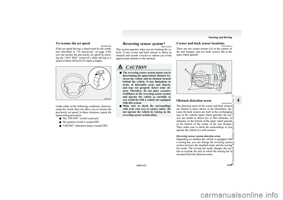
To resume the set speed
E00609800460
If the set
speed driving is deactivated by the condi-
tion described in “To deactivate” on page 4-48,
you can resume the previously set speed by press-
ing the “ACC RES” switch (C) while driving at a
speed of about 40 km/h (25 mph) or higher. Under either of the following conditions, however,
using the
switch
does not allow you to resume the
previously set speed. In these situations, repeat the
speed setting procedure:
l The “ON OFF” switch is pressed.
l The ignition switch is turned OFF.
l “CRUISE” indication lamp is turned OFF. Reversing sensor system*
E00615500055
This system operates
when you are backing the ve-
hicle. It uses corner and back sensors to detect an
obstacle and sounds a buzzer to inform you of the
approximate distance to the obstacle. CAUTION
l
The reversing sensor system assists you in
determining the approximate distance be-
tween the
vehicle
and an obstacle located
behind the vehicle. It has limitations in
terms of detectable areas and objects,
and may not properly detect some ob-
jects. Therefore, do not place excessive
confidence in the reversing sensor system
and operate the vehicle as carefully as
you would do with a vehicle not equipped
with this system.
l Make sure to check the surroundings
with your own eyes to ensure safety. Do
not operate the vehicle by relying on the
reversing sensor system alone. Corner and back sensor locations
E00618500014
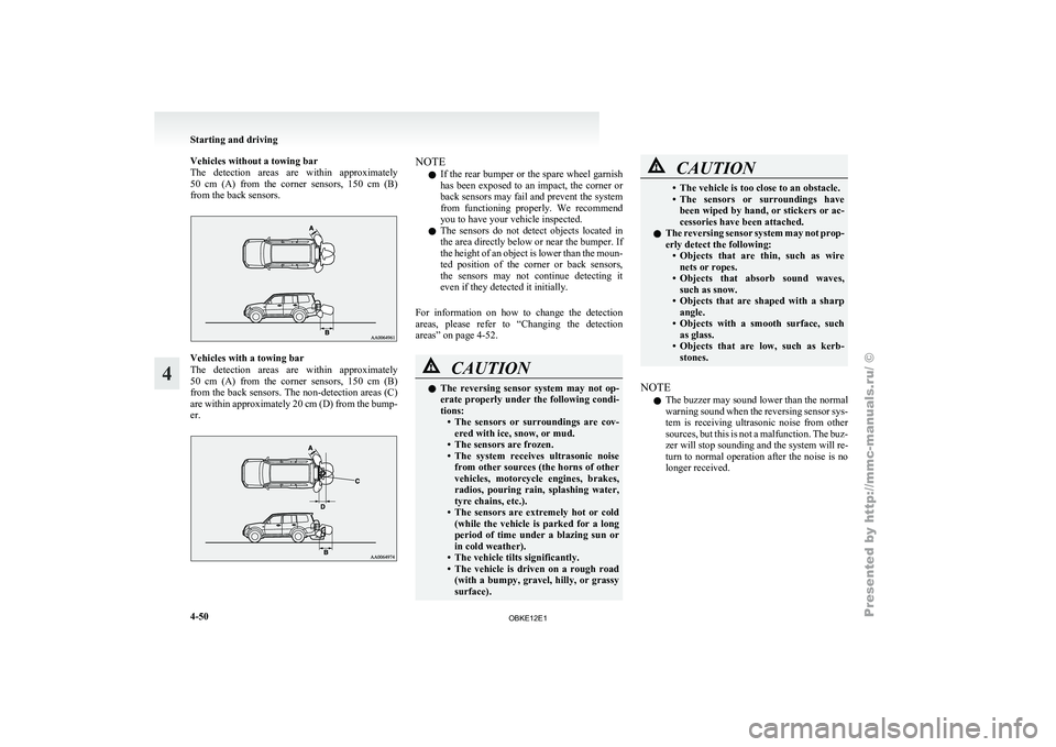
There are two
corner sensors (A) at the corners of
the rear bumper, and two back sensors (B) in the
spare wheel garnish. Obstacle detection areas
E00615600261
The detection areas of the corner and back sensors
are limited to
those shown in the illustration. Be-
cause the back sensors are built in the overhanging
area of the vehicle (spare wheel garnish), the sen-
sors are unable to detect low or thin obstacles, or
obstacles on the bottom of the spare wheel garnish
or the bottom of the centre of the rear bumper.
Thus, make sure to check the surroundings as you
operate the vehicle in a safe manner.
Reversing sensor system detection areas
Depending on whether the vehicle is equipped with
a towing bar, you can change the reversing sensor
system between the standard mode and the towing
bar mode. The towing bar mode changes the sys-
tem to exclude the area in which the towing bar is
mounted from the detection areas. Starting and driving
4-49 4
OBKE12E1
Page 175 of 377
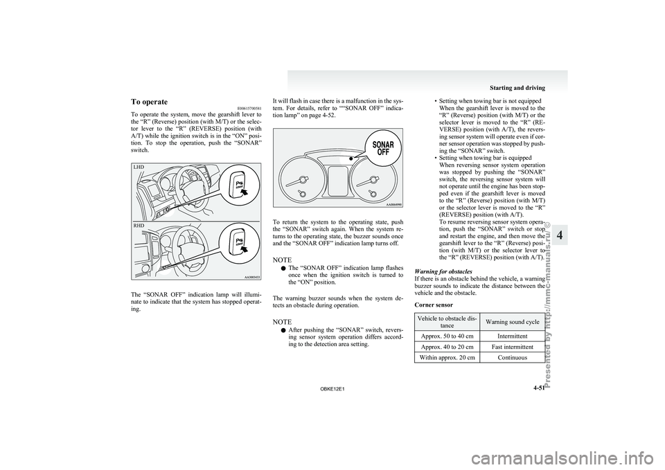
Vehicles without a towing bar
The detection areas
are within approximately
50 cm (A) from the corner sensors, 150 cm (B)
from the back sensors. Vehicles with a towing bar
The detection
areas
are within approximately
50 cm (A) from the corner sensors, 150 cm (B)
from the back sensors. The non-detection areas (C)
are within approximately 20 cm (D) from the bump-
er. NOTE
l If
the rear
bumper or the spare wheel garnish
has been exposed to an impact, the corner or
back sensors may fail and prevent the system
from functioning properly. We recommend
you to have your vehicle inspected.
l The sensors do not detect objects located in
the area directly below or near the bumper. If
the height of an object is lower than the moun-
ted position of the corner or back sensors,
the sensors may not continue detecting it
even if they detected it initially.
For information on how to change the detection
areas, please refer to “Changing the detection
areas” on page 4-52. CAUTION
l
The reversing
sensor
system may not op-
erate properly under the following condi-
tions: • The sensors or surroundings are cov-ered with ice, snow, or mud.
• The sensors are frozen.
• The system receives ultrasonic noise from other sources (the horns of other
vehicles, motorcycle engines, brakes,
radios, pouring rain, splashing water,
tyre chains, etc.).
• The sensors are extremely hot or cold (while the vehicle is parked for a long
period of time under a blazing sun or
in cold weather).
• The vehicle tilts significantly.
• The vehicle is driven on a rough road (with a bumpy, gravel, hilly, or grassy
surface). CAUTION
• The vehicle is too close to an obstacle.
• The sensors
or
surroundings have
been wiped by hand, or stickers or ac-
cessories have been attached.
l The reversing sensor system may not prop-
erly detect the following:
• Objects that are thin, such as wirenets or ropes.
• Objects that absorb sound waves, such as snow.
• Objects that are shaped with a sharp angle.
• Objects with a smooth surface, such as glass.
• Objects that are low, such as kerb- stones.
NOTE l The
buzzer may
sound lower than the normal
warning sound when the reversing sensor sys-
tem is receiving ultrasonic noise from other
sources, but this is not a malfunction. The buz-
zer will stop sounding and the system will re-
turn to normal operation after the noise is no
longer received. Starting and driving
4-50
4
OBKE12E1
Page 176 of 377
To operate
E00615700581
To operate the
system, move the gearshift lever to
the “R” (Reverse) position (with M/T) or the selec-
tor lever to the “R” (REVERSE) position (with
A/T) while the ignition switch is in the “ON” posi-
tion. To stop the operation, push the “SONAR”
switch.
LHD
RHD The “SONAR OFF” indication lamp will illumi-
nate to
indicate
that the system has stopped operat-
ing. It will flash in case there is a malfunction in the sys-
tem. For
details,
refer to ““SONAR OFF” indica-
tion lamp” on page 4-52. To return the system to the operating state, push
the “SONAR” switch
again. When the system re-
turns to the operating state, the buzzer sounds once
and the “SONAR OFF” indication lamp turns off.
NOTE
l The “SONAR OFF” indication lamp flashes
once when the ignition switch is turned to
the “ON” position.
The warning buzzer sounds when the system de-
tects an obstacle during operation.
NOTE l After pushing the “SONAR” switch, revers-
ing sensor system operation differs accord-
ing to the detection area setting. • Setting when towing bar is not equipped
When the gearshift
lever is moved to the
“R” (Reverse) position (with M/T) or the
selector lever is moved to the “R” (RE-
VERSE) position (with A/T), the revers-
ing sensor system will operate even if cor-
ner sensor operation was stopped by push-
ing the “SONAR” switch.
• Setting when towing bar is equipped When reversing sensor system operation
was stopped by pushing the “SONAR”
switch, the reversing sensor system will
not operate until the engine has been stop-
ped even if the gearshift lever is moved
to the “R” (Reverse) position (with M/T)
or the selector lever is moved to the “R”
(REVERSE) position (with A/T).
To resume reversing sensor system opera-
tion, push the “SONAR” switch or stop
and restart the engine, and then move the
gearshift lever to the “R” (Reverse) posi-
tion (with M/T) or the selector lever to
the “R” (REVERSE) position (with A/T).
Warning for obstacles
If there is an obstacle behind the vehicle, a warning
buzzer sounds to indicate the distance between the
vehicle and the obstacle.
Corner sensor Vehicle to obstacle dis-
tance Warning sound cycle
Approx. 50 to 40 cm Intermittent
Approx. 40 to 20 cm Fast intermittent
Within approx. 20 cm Continuous Starting and driving
4-51 4
OBKE12E1
Page 177 of 377
Back sensor (vehicles without a towing bar)
Vehicle to obstacle dis-
tance Warning sound cycle
Approx. 150 to 80 cm Intermittent Approx. 80 to 40 cm Fast intermittent
Within approx. 40 cm Continuous Back sensor (vehicles with a towing bar)
Vehicle to obstacle dis-
tance Warning sound cycle
Approx. 150 to 120 cm Intermittent Approx. 120 to 60 cm Fast intermittentWithin approx. 60 cm Continuous CAUTION
l
The distances given are to be used for ref-
erence
only, as
errors may be caused by
various factors, such as temperature, hu-
midity, or the shape of the obstacles.
Changing the detection areas E00615800032
The detection areas can be changed as follows:
Vehicles with a towing bar
While the operation
of the system is stopped at the
“SONAR” switch, push the “SONAR” switch ap-
proximately 3 seconds or more, and release it. The
buzzer sounds twice to indicate that the detection
area has been changed. Vehicles without a towing bar
While the
operation
of the system is stopped at the
“SONAR” switch, push the “SONAR” switch ap-
proximately 3 seconds or more, and release it. The
buzzer sounds once to indicate that the detection
area has been changed.
NOTE
l The detection area will not change if you
keep the “SONAR” switch pushed for 10 sec-
onds or more.
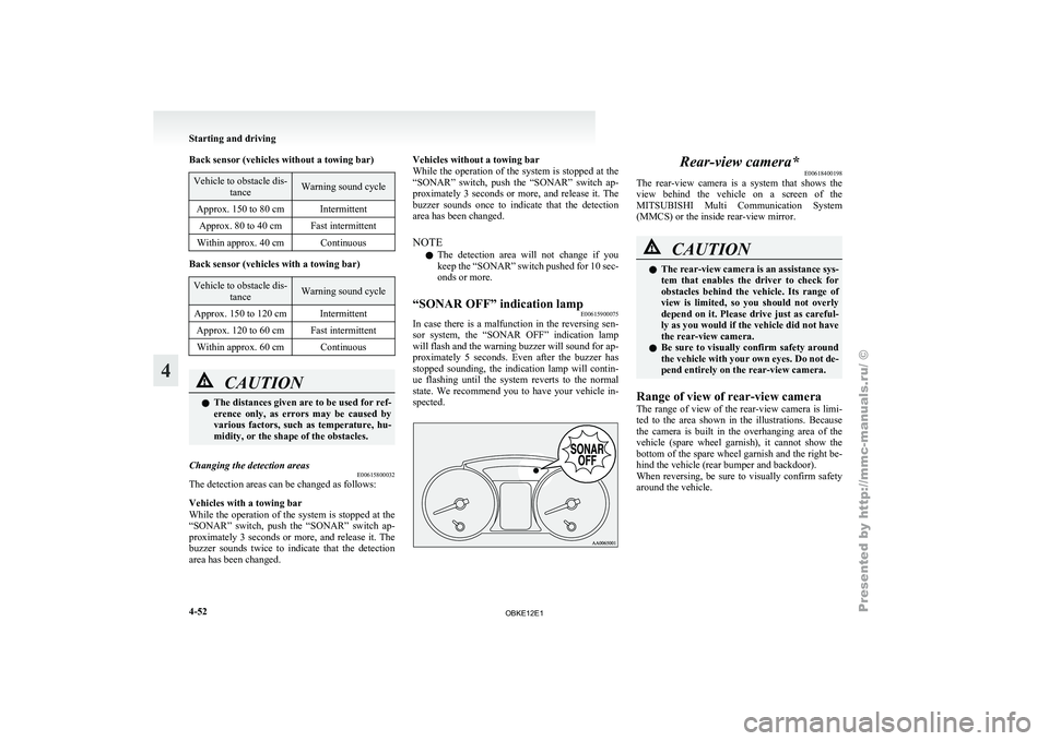
“SONAR OFF” indication lamp E00615900075
In case there is a malfunction in the reversing sen-
sor system, the
“SONAR OFF” indication lamp
will flash and the warning buzzer will sound for ap-
proximately 5 seconds. Even after the buzzer has
stopped sounding, the indication lamp will contin-
ue flashing until the system reverts to the normal
state. We recommend you to have your vehicle in-
spected. Rear-view camera*
E00618400198
The rear-view camera
is a system that shows the
view behind the vehicle on a screen of the
MITSUBISHI Multi Communication System
(MMCS) or the inside rear-view mirror. CAUTION
l
The rear-view
camera
is an assistance sys-
tem that enables the driver to check for
obstacles behind the vehicle. Its range of
view is limited, so you should not overly
depend on it. Please drive just as careful-
ly as you would if the vehicle did not have
the rear-view camera.
l Be sure to visually confirm safety around
the vehicle with your own eyes. Do not de-
pend entirely on the rear-view camera.
Range of view of rear-view camera
The range of
view of the rear-view camera is limi-
ted to the area shown in the illustrations. Because
the camera is built in the overhanging area of the
vehicle (spare wheel garnish), it cannot show the
bottom of the spare wheel garnish and the right be-
hind the vehicle (rear bumper and backdoor).
When reversing, be sure to visually confirm safety
around the vehicle. Starting and driving
4-52
4
OBKE12E1