fuel cap MITSUBISHI SHOGUN 2017 Owner's Manual (in English)
[x] Cancel search | Manufacturer: MITSUBISHI, Model Year: 2017, Model line: SHOGUN, Model: MITSUBISHI SHOGUN 2017Pages: 394, PDF Size: 19 MB
Page 2 of 394
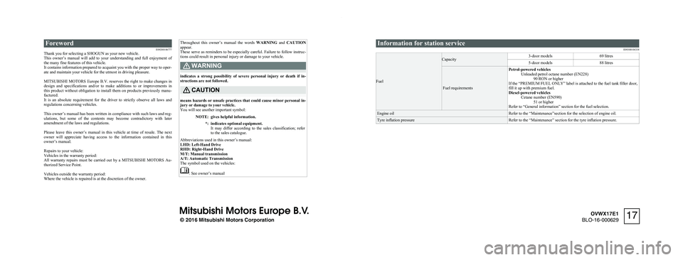
ForewordE09200106777
Thank you for selecting a SHOGUN as your new vehicle.
This owner’s manual will add to your understanding and full enjoyment of
the many fine features of this vehicle.
It contains information prepared to acquaint you with the proper way to oper-
ate and maintain your vehicle for the utmost in driving pleasure.
MITSUBISHI MOTORS Europe B.V. reserves the right to make changes in
design and specifications and/or to make additions to or improvements in
this product without obligation to install them on products previously manu- factured.
It is an absolute requirement for the driver to strictly observe all laws and
regulations concerning vehicles.
This owner’s manual has been written in compliance with such laws and reg- ulations, but some of the contents may become contradictory with later amendment of the laws and regulations.
Please leave this owner’s manual in this vehicle at time of resale. The next
owner will appreciate having access to the information contained in this
owner’s manual.
Repairs to your vehicle:
Vehicles in the warranty period:
All warranty repairs must be carried out by a MITSUBISHI MOTORS Au-
thorized Service Point.
Vehicles outside the warranty period:
Where the vehicle is repaired is at the discretion of the owner.
Throughout this owner’s manual the words WARNING and CAUTION
appear.
These serve as reminders to be especially careful. Failure to follow instruc-
tions could result in personal injury or damage to your vehicle.WARNING
indicates a strong possibility of severe personal injury or death if in- structions are not followed.
CAUTION
means hazards or unsafe practices that could cause minor personal in-
jury or damage to your vehicle.
You will see another important symbol:
NOTE:gives helpful information.*:indicates optional equipment.
It may differ according to the sales classification; refer to the sales catalogue.
Abbreviations used in this owner’s manual:
LHD: Left-Hand Drive
RHD: Right-Hand Drive
M/T: Manual transmission
A/T: Automatic Transmission
The symbol used on the vehicles:
: See owner’s manual
Information for station service
E09300104338
Fuel
Capacity3-door models69 litres5-door models88 litres
Fuel requirements
Petrol-powered vehiclesUnleaded petrol octane number (EN228)90 RON or higher
If the “PREMIUM FUEL ONLY” label is attached to the fuel tank filler door,
fill it up with premium fuel.
Diesel-powered vehicles Cetane number (EN590)51 or higher
Refer to “General information” section for the fuel selection.Engine oilRefer to the “Maintenance”section for the selection of engine oil.Tyre inflation pressureRefer to the “Maintenance” section for the tyre inflation pressure.
© 2016 Mitsubishi Motors Corporation
17
OVWX17E1
BLO-16-000629
Page 15 of 394
NOTElIn diesel-powered vehicles, poor-quality die-
sel fuel can cause deposits form in the injec- tor, resulting in black smoke and rough
idling.
If these problems occur, you are advised to add a cleaning additive to the diesel fuel
when you refuel the vehicle.
The additive will break up and remove the deposits, thereby returning the engine to anormal condition.
Be sure to use a MITSUBISHI MOTORS
GENUINE DIESEL FUEL SYSTEM CLEANER. Using an unsuitable additive
could make the engine malfunction. For de- tails, please contact your MITSUBISHI
MOTORS Authorized Service Point.E10 type petrol
E00203200019
The petrol engines are compatible with E10
type petrol (containing 10 % ethanol) con- forming to European standards EN 228.
CAUTIONl Do not use more than 10 % concentration of
ethanol (grain alcohol) by volume.
Use of more than 10 % concentration may lead to damage to your vehicle fuel system,
engine, engine sensors and exhaust system.Filling the fuel tank
E00200204087WARNINGlWhen handling fuel, comply with the safe-
ty regulations displayed by garages and filling stations.
l Before removing the fuel tank filler tube
cap, be sure to get rid of your body’s stat-
ic electricity by touching a metal part of the car or fuel pump. Any static electricity
on your body could create a spark that ig-
nites fuel vapour.
l Perform the whole refueling process
(opening the fuel tank filler door, remov-
ing the fuel tank filler tube cap, etc.) by yourself. Do not let any other person come
near the fuel tank filler. If you allowed a
person to help you and that person was carrying static electricity, fuel vapour
could be ignited.
l Do not move away from the fuel tank fill-
er door until refueling is finished. If you moved away and did something else (for
example, cleaning your windscreen) part- way through the refueling process, you
could pick up a fresh charge of static elec-
tricity.
l If the fuel tank filler tube cap must be re-
placed, use only a MITSUBISHI
MOTORS genuine part.
Fuel tank capacity
3-door models: 69 litres
5-door models: 88 litres
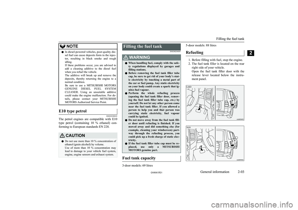
Refueling
1. Before filling with fuel, stop the engine.
2. The fuel tank filler is located on the rear
right side of your vehicle.
Open the fuel tank filler door with the
release lever located below the instru- ment panel.
LHD
Filling the fuel tank
2-03OVWX17E1General information2 RHD
Page 16 of 394
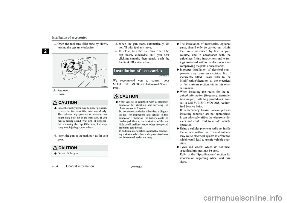
3.Open the fuel tank filler tube by slowly
turning the cap anticlockwise.
A- Remove B- Close
CAUTIONl Since the fuel system may be under pressure,
remove the fuel tank filler tube cap slowly. This relieves any pressure or vacuum that
might have built up in the fuel tank. If you
hear a hissing sound, wait until it stops be- fore removing the cap. Otherwise, fuel may
spray out, injuring you or others.
4. Insert the gun in the tank port as far as it
goes.
CAUTIONl Do not tilt the gun.5.
When the gun stops automatically, do
not fill with fuel any more.
6. To close, turn the fuel tank filler tube
cap slowly clockwise until you hear clicking sounds, then gently push the
fuel tank filler door closed.Installation of accessories
E00200302345
We recommend you to consult yourMITSUBISHI MOTORS Authorized Service
Point.
CAUTIONl Your vehicle is equipped with a diagnosis
connector for checking and servicing theelectronic control system.
Do not connect a device other than a diagno-
sis tool for inspections and service to this connector. Otherwise, the battery could be
discharged, the electronic devices of the ve- hicle could malfunction, or other unexpected
problems could result.
In addition, malfunctions caused by connect-
ing a device other than a diagnosis tool may not be covered under warranty.l The installation of accessories, optional
parts, should only be carried out within
the limits prescribed by law in your
country, and in accordance with the guidelines fitting instructions and warn-
ings contained within the documents ac-
companying the parts or accessories.
l Improper installation of electrical com-
ponents may cause an electrical fire if
incorrectly fitted. Please refer to the Modification/alteration to the electrical
or fuel systems section within this own-
er’s manual.
l When installing the radio, for the re-
quired information (frequency, transmis-
sion output, installing procedure), con- sult a MITSUBISHI MOTORS Author-
ized Service Point.
If the frequency, transmission output and installing condition are not appropriate,
it can adversely affect the electronic de- vices and could lead to unsafe vehicle operation.
l Using a cellular phone or radio set inside
the vehicle without an external antenna
may cause electrical system interference, which could lead to unsafe vehicle oper-ation.
l Tyres and wheels which do not meet
specifications must not be used.
Refer to the “Specifications” section for
information regarding wheel and tyre
sizes.
Installation of accessories
2-04OVWX17E1General information2
Page 152 of 394
NOTElWhen the engine has not been started within
about 5 seconds after the diesel preheat indi-
cation lamp went out, return the ignition key to the “LOCK” position. Then, turn the key
to the “ON” position to preheat the engine
again.
l When the engine is warm, the diesel preheat
indication lamp does not come on even if the
ignition key is placed in the “ON” position. Start the engine by turning the ignition key
right to the “START” position.
6. Turn the ignition key to the “START”
position without depressing the accelera- tor pedal, and release it when the engine
starts.
Fuel injection amount learning
process (diesel-powered vehi-cles)
E00616000044
To keep exhaust emissions and engine noise low, the engine very occasionally performs a
learning process for the fuel injection
amount.
The engine sounds slightly different from
usual while the learning process is taking place. The change in the engine sound does
not indicate a fault.
NOx trap catalyst
(dieselpowered vehicles)* E00649200020
A NOx (nitrogen oxide) trap catalyst absorbs
the NOx contained in the exhaust gas of the diesel engine.
To maintain the NOx absorbing function, the
fuel is supplied regularly to the catalyst while
driving, and the catalyst reduces NOx to harmless N2 (nitrogen).
The bar graph of momentary fuel consump-
tion in the centre information display and en- gine sound change while NOx is being
purged automatically by the catalyst. These
do not indicate a fault.Diesel particulate filter
(DPF)* E00619801460
The diesel particulate filter (DPF) is a devicethat captures most of the particulate matter
(PM) in the exhaust emissions of the diesel
engine. The DPF automatically burns away trapped PM during vehicle operation. Under
certain driving conditions, however, the DPF is not able to burn away all of the trapped PM
and, as a result, an excessive amount of PM accumulates inside it.
WARNINGl The DPF reaches very high temperatures.
Do not park your vehicle in areas where
combustible materials such as dry grass
or leaves can come in contact with a hot exhaust system since a fire could occur.CAUTIONl Do not use any type of fuel or engine oil that
is not specified for your vehicle. Also, do not use any moisture-removing agent or oth-
er fuel additive. Such substances could have a detrimental effect on the DPF.
Refer to “Fuel selection” on page 2-02 and
“Engine oil” on page 10-04.NOTEl To minimize the likelihood of excessive ac-
cumulation of PM, try to avoid driving for long periods at low speeds and repeatedly
driving short distances, and try to keep high
engine speed driving as much as possible.
NOx trap catalyst (dieselpowered vehicles)*
6-14OVWX17E1Starting and driving6
Page 188 of 394
Each tyre, including the spare, should be
checked monthly when cold and inflated to the inflation pressure recommended by thevehicle manufacturer on the tyre inflation
pressure label. (If your vehicle has tyres of a different size than the size indicated on the
tyre inflation pressure label, you should de-
termine the proper tyre inflation pressure for those tyres.)
As an added safety feature, your vehicle has been equipped with the tyre pressure moni-
toring system (TPMS) that illuminates a low
tyre pressure telltale when one or more of
your tyres is significantly under-inflated.
Accordingly, when the low tyre pressure tell-
tale illuminates, you should stop and check your tyres as soon as possible, and inflate
them to the proper pressure. Driving on a sig- nificantly under-inflated tyre causes the tyre to overheat and can lead to tyre failure.
Under-inflation also reduces fuel efficiency
and tyre tread life, and may affect the vehi- cle’s handling and stopping ability.
Please note that the tyre pressure monitoring
system (TPMS) is not a substitute for proper tyre maintenance, and it is the driver’s re-sponsibility to maintain correct tyre pressure,
even if under-inflation has not reached the level to trigger illumination of the tyre pres-
sure monitoring system (TPMS) low tyre pressure telltale.Your vehicle has also been equipped with a
warning lamp to indicate when the system is
not operating properly.
The warning lamp is combined with the low
tyre pressure telltale.
When the system detects a malfunction, the telltale will flash for approximately one mi-nute and then remain continuously illumina-
ted. This sequence will continue upon subse- quent vehicle start-ups as long as the mal-
function exists.
When the warning lamp is illuminated, the
system may not be able to detect or signal low tyre pressure as intended.
The tyre pressure monitoring system (TPMS)
malfunctions may occur for a variety of rea- sons, including the installation of replace- ment or alternate tyres or wheels on the vehi-
cle that prevent the tyre pressure monitoring system (TPMS) from functioning properly.
Always check the tyre pressure monitoring system (TPMS) malfunction telltale after re- placing one or more tyres or wheels on yourvehicle to ensure that the replacement or al-
ternate tyres and wheels allow the tyre pres- sure monitoring system (TPMS) to continueto function properly.If the warning lamp illuminates
while driving
E00637300082
1. If the warning lamp illuminates, avoid
hard braking, sharp steering manoeuvres
and high speeds. You should stop and
adjust the tyres to the proper inflationpressure as soon as possible. Refer to
“Tyres” on page 10-11.NOTEl When inspecting or adjusting the tyre pres-
sure, do not apply excessive force to the valve stem to avoid breakage.
l After inspecting or adjusting the tyre pres-
sure, always reinstall the valve cap on the valve stem.
Without the valve cap, dirt or moisture could
get into the valve, resulting in damage to the tyre inflation pressure sensor.
l Do not use metal valve caps, which may
cause a metal reaction, resulting in corrosion
and damage of the tyre inflation pressure sensors.
l Once adjustments have been made, the
warning lamp will go off after a few minutes of driving.
2. If the warning lamp remains illuminated
after you have been driving for about 10
minutes after you adjust the tyre infla- tion pressure, one or more of the tyresmay have a puncture. Inspect the tyreand if it has a puncture, have it repaired
by a MITSUBISHI MOTORS Author-
ized Service Point as soon as possible.
Tyre pressure monitoring system (TPMS)*
6-50OVWX17E1Starting and driving6
Page 323 of 394

7.If the oil level is below the specified
limit, remove the cap located on the cyl- inder head cover and add enough oil to
raise the level to within the specified range. Do not overfill to avoid engine
damage. Be sure to use the specified en-
gine oil and do not mix various types of
oil.
8. After adding oil, close the cap securely.
9. Confirm the oil level by repeating step 4
to 6.
Use only the recommended oils with an ACEA or API classification as specified in
this manual.NOTEl For 3200 models, check or refill the oil ac-
cording to the following manner.
• When the oil level is checked in step 6
above, check it on a low side of the dip-
stick because it is different in appearance
of oil level in the two sides of the dip-
stick.
• The oil level should be within the range
(A) to (C) (oil replacement indication
mark) on the dipstick.
If the oil level is beyond the oil replace- ment indication mark (C), replace the oil
as soon as possible.
Then, the oil should be refilled to the maximum level (B).NOTE• The engine oil will increase due to a little
fuel getting mixed in the engine oil when the DPF regenerates to burn away the PM
(particulate matter). It does not indicate a
malfunction.
In the following conditions, the engine oil level may increase easily. We recommendyou to have it checked frequently.
• frequent driving at uphill and downhill
• frequent driving at high altitudes
• frequent and extended idling
• frequent driving through a traffic jam
l The engine oil will deteriorate rapidly if the
vehicle is subjected to severe conditions, re- quiring earlier oil replacement. Please refer
to the maintenance schedule.
l For handling of used engine oils, refer to
page 2-06.Selection of engine oil
Petrol-powered vehicles
l Select engine oil of the proper SAE vis-
cosity number according to the atmos- pheric temperature.
SAE 0W-20*, 0W-30, 5W-30, and 5W-40 engine oils can only be used if
they meet ACEA A3/B3, A3/B4 or
A5/B5 and API SM (or higher) specifi-
cations.
*: Only the vehicles complying with the Euro 5 regulation
l Use engine oil conforming to the follow-
ing classification: • API classification: “For service SM”
or higher
• ILSAC certificated oil
• ACEA classification: “For service A1/B1, A3/B3 , A3/B4 or
A5/B5”
Engine oil
10-05OVWX17E1Maintenance10
Page 338 of 394

No.SymbolElectricalsystemCapaci- ty31—Spare fuse30 A32—Spare fuse25 A
lSome fuses may not be installed on your
vehicle, depending on the vehicle model
or specifications.
l The table above shows the main equip-
ment corresponding to each fuse.
The fuse block does not contain spare
7.5 A and 15 A fuses. If a fuse of one of these capacities blows, replace it tempo-
rarily by borrowing the one that matches
from:
7.5 A: Outside rear-view mirrors
15 A: Cigarette lighter
Replace the borrowed fuse as soon as
possible.
Engine compartment fuse loca-
tion table
E01008001913
Engine compartment fuse location (Type A)
No.SymbolElectrical systemCapaci- ty1Alternator140 A *12Fuse (+B)60 A*13Ignition
switch40 A *1*1
: Fusible link
*2 : Vehicles without discharge headlamps
*3 : Vehicles with discharge headlampsNo.SymbolElectrical
systemCapaci- ty4Electric win-dow control30 A *15Engine con-
trol20 A *16Fuel pump20 A7Rear heater25 A8Accessory
socket25 A9Fuel line heat- er25 A10Condenserfan motor25 A11Rear air con- ditioning20 A
12
Horn (Theft-
alarm system)
15 A
Wiper de-icer13Horn10 A14Automatic
transmission20 A*1 : Fusible link
*2 : Vehicles without discharge headlamps
*3 : Vehicles with discharge headlamps
Fuses
10-20OVWX17E1Maintenance10
Page 351 of 394

Vehicle labeling................................................................................ 11-02
Vehicle dimensions........................................................................... 11-04
Vehicle performance......................................................................... 11-06 Vehicle weight.................................................................................. 11-06
Engine specifications........................................................................ 11-10
Electrical system............................................................................... 11-11
Tyres and wheels...............................................................................11-11
Fuel consumption.............................................................................. 11-12
Refill capacities................................................................................. 11-14Specifications
OVWX17E111
Page 367 of 394
A
Accessory (Installation).....................................2-04
Accessory socket............................................... 7-77
Active stability & traction control (ASTC)....... 6-40
Additional equipment...................................... 10-18
Air conditioning Front automatic air conditioning................... 7-03
Important operation tips for the air conditioning................................................. 7-11
Rear air conditioning.....................................7-09
Air purifier (with deodorizing function)........... 7-11
Airbag................................................................ 4-36 Caution for installing the child re-straint on vehicle with a front pas-
senger’s airbag.....................................4-25,4-39
Antenna............................................................. 7-50
Anti-lock brake system (ABS).......................... 6-37 Warning lamp................................................6-38
Approach lamps.................................................3-08
Armrest..................................................... 4-08,4-10
Ashtray.............................................................. 7-75
Audio LW/MW/FM radio/CD player...................... 7-12
To listen to a disc in the Video En- tertainment System...................................... 7-39
Troubleshooting............................................ 7-47
Auto-cutout function......................................... 7-81
Automatic headlamp levelling.......................... 5-41
Automatic high-beam system............................ 5-36 Automatic high-beam system warning lamp 5-39
Automatic transmission
Fluid............................................................ 11-14
Selector lever operation................................ 6-15
Selector lever position...................................6-17
Sports mode.................................................. 6-17
B
Backdoor........................................................... 3-09
Battery............................................................. 10-09 Charge warning display................................ 5-12
Discharged battery (Emergency starting)..... 8-02
Specifications.............................................. 11-11
Bleeding the fuel system................................... 8-06
Bluetooth® 2.0 interface................................... 7-50
Bonnet............................................................. 10-03
Brake Anti-lock brake............................................. 6-37
Brake assist system....................................... 6-36
Braking.......................................................... 6-35
Fluid.................................................. 10-08,11-14
Parking brake................................................ 6-04
Power brakes................................................. 6-35
Warning lamp................................................5-10
Bulb capacity........................................ 10-23,10-25
C
Card holder................................................7-75,7-83
Cargo loads........................................................6-59
Catalytic converter.......................................... 10-02 Cautions on handling of 4-wheel drive vehicles................................................... 6-33
Central door locks............................................. 3-07
Centre console box............................................ 7-83
Centre information display................................ 5-12
Changing a fuse............................................... 10-22 Charge warning display.....................................5-12Check engine warning lamp.............................. 5-11Child restraint.................................................... 4-26 Caution for installing the child re-straint on vehicle with a front pas-
senger’s airbag.....................................4-25,4-39
Child-protection rear doors............................... 3-08
Cigarette lighter................................................. 7-76
Cleaning Aluminium wheels........................................ 9-05Chrome parts................................................. 9-05
Exterior of your vehicle................................ 9-03
Genuine leather............................................. 9-03
Interior of your vehicle................................. 9-02
Plastic, vinyl leather, etc............................... 9-02
Polishing....................................................... 9-04
Sunroof.......................................................... 9-06
Washing........................................................ 9-03
Waxing.......................................................... 9-04
Coat hooks......................................................... 7-88
Combination headlamps and dipper switch...... 5-34
Convenient hook............................................... 7-87
Coolant (engine)....................................10-06,11-14
Cruise control.................................................... 6-44
Cup holder......................................................... 7-85
Curtain airbag system........................................ 4-44
D
Daytime dipper button.......................................5-07
Daytime running lamps..................................... 5-35
Demister (rear window).................................... 5-50
Diesel particulate filter (DPF)........................... 6-14
Alphabetical index
12- 1
OVWX17E1Alphabetical index
Page 368 of 394

Diesel preheat indication lamp.......................... 5-09
Digital clock Time Setting.................................................. 7-44
Dimensions...................................................... 11-04
Dipper (High/Low beam change)......................5-36
Door ajar warning lamp.....................................5-12
Door courtesy lamps............................... 7-81,10-25
Bulb capacity.............................................. 10-25
Replacement................................................ 10-31
Doors
Central door locks......................................... 3-07
Child-protection............................................ 3-08
Lock and unlock............................................ 3-06
Driving, alcohol and drugs................................ 6-02
E
Economical driving........................................... 6-02
Electric window control.................................... 3-16 Switch........................................................... 3-16
Timer function.............................................. 3-18
Electrical system............................................. 11-11
Electronic immobilizer (Anti-theft starting system)................................................ 3-03
Emergency starting............................................8-02
Engine Coolant..............................................10-06,11-14MIVEC.......................................................... 6-13
Number....................................................... 11-03
Oil..................................................... 10-04,11-14
Overheating................................................... 8-04
Specifications.............................................. 11-10
Used engine oils safety instructions and disposal information............................. 2-06
Water temperature gauge.............................. 5-06
Exterior and interior lamp operation............... 10-17
F
FluidAutomatic transmission fluid...................... 11-14
Brake fluid........................................ 10-08,11-14
Engine coolant.................................. 10-06,11-14
Power steering fluid.......................... 10-09,11-14
Washer fluid..................................... 10-07,11-14
Fog lamp switch................................................ 5-43
Foot lamps and ceiling lamp............................. 7-80
For cold and snowy weather............................10-17
Front automatic air conditioning....................... 7-03
Front fog lamps Bulb capacity.............................................. 10-23
Indication lamp............................................. 5-09
Replacement................................................ 10-27
Switch........................................................... 5-43
Front passenger’s airbag OFF indication lamp. 4-40
Front seats......................................................... 4-05
Front turn-signal lamps Bulb capacity.............................................. 10-23
Replacement................................................ 10-26
Fuel consumption............................................ 11-12
Fuel
Filling the fuel tank....................................... 2-03Fuel filter indication lamp............................. 5-10
Fuel gauge..................................................... 5-05 Fuel selection................................................ 2-02
Low fuel warning lamp................................. 5-06
Modification/alterations to the electrical or fuel systems............................. 2-05
Tank capacity................................................ 2-03
Fuses................................................................ 10-18
Fusible links.................................................... 10-18
G
Gauges.......................................................5-02,5-08
General maintenance....................................... 10-17
General vehicle data........................................ 11-04
Genuine parts.....................................................2-05
Glove box.......................................................... 7-82
Glove box lamp Bulb capacity.............................................. 10-25
Replacement................................................ 10-32
H
Hazard warning flasher switch.......................... 5-42
Hazard warning indication lamps......................5-09
HDMI port......................................................... 7-74
Head restraints................................................... 4-12
Headlamp levelling........................................... 5-40
Headlamp washer switch...................................5-48
Headlamps Bulb capacity.............................................. 10-23
Headlamp flasher.......................................... 5-39 Replacement................................................ 10-25
Switch........................................................... 5-34
Heated mirror.................................................... 6-10
Heated seats....................................................... 4-09
High-beam indication lamp............................... 5-09
High-mounted stop lamp (bulb type) Bulb capacity.............................................. 10-23
Replacement................................................ 10-29
Hinges and latches lubrication........................ 10-17
Alphabetical index
12- 2 OVWX17E1Alphabetical index