fuel pressure MITSUBISHI SHOGUN 2017 Owner's Manual (in English)
[x] Cancel search | Manufacturer: MITSUBISHI, Model Year: 2017, Model line: SHOGUN, Model: MITSUBISHI SHOGUN 2017Pages: 394, PDF Size: 19 MB
Page 2 of 394
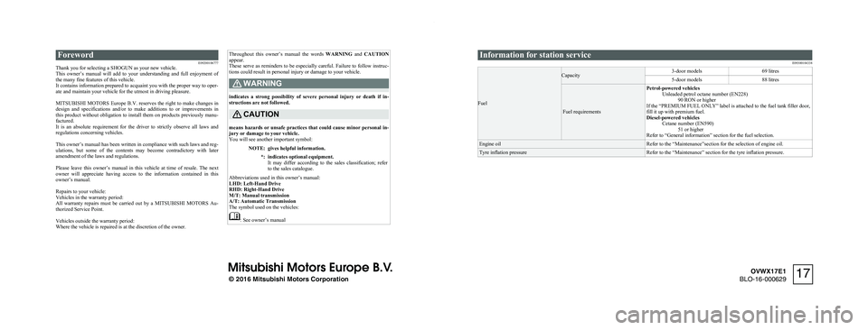
ForewordE09200106777
Thank you for selecting a SHOGUN as your new vehicle.
This owner’s manual will add to your understanding and full enjoyment of
the many fine features of this vehicle.
It contains information prepared to acquaint you with the proper way to oper-
ate and maintain your vehicle for the utmost in driving pleasure.
MITSUBISHI MOTORS Europe B.V. reserves the right to make changes in
design and specifications and/or to make additions to or improvements in
this product without obligation to install them on products previously manu- factured.
It is an absolute requirement for the driver to strictly observe all laws and
regulations concerning vehicles.
This owner’s manual has been written in compliance with such laws and reg- ulations, but some of the contents may become contradictory with later amendment of the laws and regulations.
Please leave this owner’s manual in this vehicle at time of resale. The next
owner will appreciate having access to the information contained in this
owner’s manual.
Repairs to your vehicle:
Vehicles in the warranty period:
All warranty repairs must be carried out by a MITSUBISHI MOTORS Au-
thorized Service Point.
Vehicles outside the warranty period:
Where the vehicle is repaired is at the discretion of the owner.
Throughout this owner’s manual the words WARNING and CAUTION
appear.
These serve as reminders to be especially careful. Failure to follow instruc-
tions could result in personal injury or damage to your vehicle.WARNING
indicates a strong possibility of severe personal injury or death if in- structions are not followed.
CAUTION
means hazards or unsafe practices that could cause minor personal in-
jury or damage to your vehicle.
You will see another important symbol:
NOTE:gives helpful information.*:indicates optional equipment.
It may differ according to the sales classification; refer to the sales catalogue.
Abbreviations used in this owner’s manual:
LHD: Left-Hand Drive
RHD: Right-Hand Drive
M/T: Manual transmission
A/T: Automatic Transmission
The symbol used on the vehicles:
: See owner’s manual
Information for station service
E09300104338
Fuel
Capacity3-door models69 litres5-door models88 litres
Fuel requirements
Petrol-powered vehiclesUnleaded petrol octane number (EN228)90 RON or higher
If the “PREMIUM FUEL ONLY” label is attached to the fuel tank filler door,
fill it up with premium fuel.
Diesel-powered vehicles Cetane number (EN590)51 or higher
Refer to “General information” section for the fuel selection.Engine oilRefer to the “Maintenance”section for the selection of engine oil.Tyre inflation pressureRefer to the “Maintenance” section for the tyre inflation pressure.
© 2016 Mitsubishi Motors Corporation
17
OVWX17E1
BLO-16-000629
Page 12 of 394

Outside (Rear)E001005072241. Rear fog lamp p. 5-43, 10-23, 10-29
2. Rear turn-signal lamps* p. 5-42, 10-23, 10-28
3. Tail lamps* p. 5-34, 10-23, 10-28
4. Licence plate lamps p. 5-34, 10-23, 10-29
5. Spare wheel garnish p. 8-10
6. Rear-view camera* p. 6-56
7. Spare wheel p. 8-10
8. High-mounted stop lamp p. 10-23, 10-29
9. Rear window wiper and washer p. 5-48
10. Antenna* p. 7-50
11. Backdoor p. 3-09
12. Fuel tank filler p. 2-03
13. Tyre inflation pressure p. 10-11 Tyre pressure monitoring system* p. 6-48
Changing tyres p. 8-09
Tyre rotation p. 10-13
Tyre chains p. 10-14
14. Corner and back sensor* p. 6-53
15. Rear turn-signal lamps* p. 5-42, 10-23, 10-28
16. Stop and tail lamps p. 5-34, 10-23, 10-28 Stop lamps* p. 10-23, 10-28
17. Reversing lamps p. 10-23, 10-28
18. Rear turn-signal lamps* p. 5-42, 10-23, 10-28
19. Reversing lamps p. 10-23, 10-28
20. Stop and tail lamps p. 5-34, 10-23, 10-28 Stop lamps* p. 10-23, 10-28
Outside (Rear)
1-10OVWX17E1Overview13-door models 5-door models
Page 16 of 394
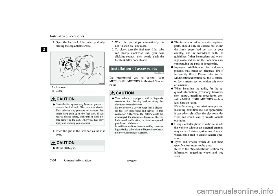
3.Open the fuel tank filler tube by slowly
turning the cap anticlockwise.
A- Remove B- Close
CAUTIONl Since the fuel system may be under pressure,
remove the fuel tank filler tube cap slowly. This relieves any pressure or vacuum that
might have built up in the fuel tank. If you
hear a hissing sound, wait until it stops be- fore removing the cap. Otherwise, fuel may
spray out, injuring you or others.
4. Insert the gun in the tank port as far as it
goes.
CAUTIONl Do not tilt the gun.5.
When the gun stops automatically, do
not fill with fuel any more.
6. To close, turn the fuel tank filler tube
cap slowly clockwise until you hear clicking sounds, then gently push the
fuel tank filler door closed.Installation of accessories
E00200302345
We recommend you to consult yourMITSUBISHI MOTORS Authorized Service
Point.
CAUTIONl Your vehicle is equipped with a diagnosis
connector for checking and servicing theelectronic control system.
Do not connect a device other than a diagno-
sis tool for inspections and service to this connector. Otherwise, the battery could be
discharged, the electronic devices of the ve- hicle could malfunction, or other unexpected
problems could result.
In addition, malfunctions caused by connect-
ing a device other than a diagnosis tool may not be covered under warranty.l The installation of accessories, optional
parts, should only be carried out within
the limits prescribed by law in your
country, and in accordance with the guidelines fitting instructions and warn-
ings contained within the documents ac-
companying the parts or accessories.
l Improper installation of electrical com-
ponents may cause an electrical fire if
incorrectly fitted. Please refer to the Modification/alteration to the electrical
or fuel systems section within this own-
er’s manual.
l When installing the radio, for the re-
quired information (frequency, transmis-
sion output, installing procedure), con- sult a MITSUBISHI MOTORS Author-
ized Service Point.
If the frequency, transmission output and installing condition are not appropriate,
it can adversely affect the electronic de- vices and could lead to unsafe vehicle operation.
l Using a cellular phone or radio set inside
the vehicle without an external antenna
may cause electrical system interference, which could lead to unsafe vehicle oper-ation.
l Tyres and wheels which do not meet
specifications must not be used.
Refer to the “Specifications” section for
information regarding wheel and tyre
sizes.
Installation of accessories
2-04OVWX17E1General information2
Page 90 of 394

InstrumentsE00500102896
1- Speedometer (km/h or mph + km/h)
2- Tachometer
3- Tripmeter reset button/Daytime dipper button
4- Fuel gauge
5- Odometer/Tripmeter/Service reminder/ Tyre pressure monitoring system*
6- Gearshift indicator ® p. 6-17
7- Water temperature gauge
Tachometer
E00500300458
The tachometer indicates the engine speed
(r/min). The tachometer helps you to obtain
more economical driving and also warns you
of excessive engine speeds (Red zone).
CAUTIONl When driving, watch the tachometer to make
sure that the engine speed indication does not rise into the red zone (excessive enginerpm).Odometer/Tripmeter/Service
reminder/Tyre pressure moni-toring system*
E00500602237
With the ignition switch in the “ON” posi-
tion, odometer, tripmeter, service reminder
and tyre pressure monitoring system indica-
tions are given.
A- Odometer/Tripmeter/Service reminder/ Tyre pressure monitoring system*
B- Reset button
Each time you press the reset button (B) less
than 1 second, the display switches in the fol- lowing order.
Instruments
5-02OVWX17E1Instruments and controls5
Page 96 of 394
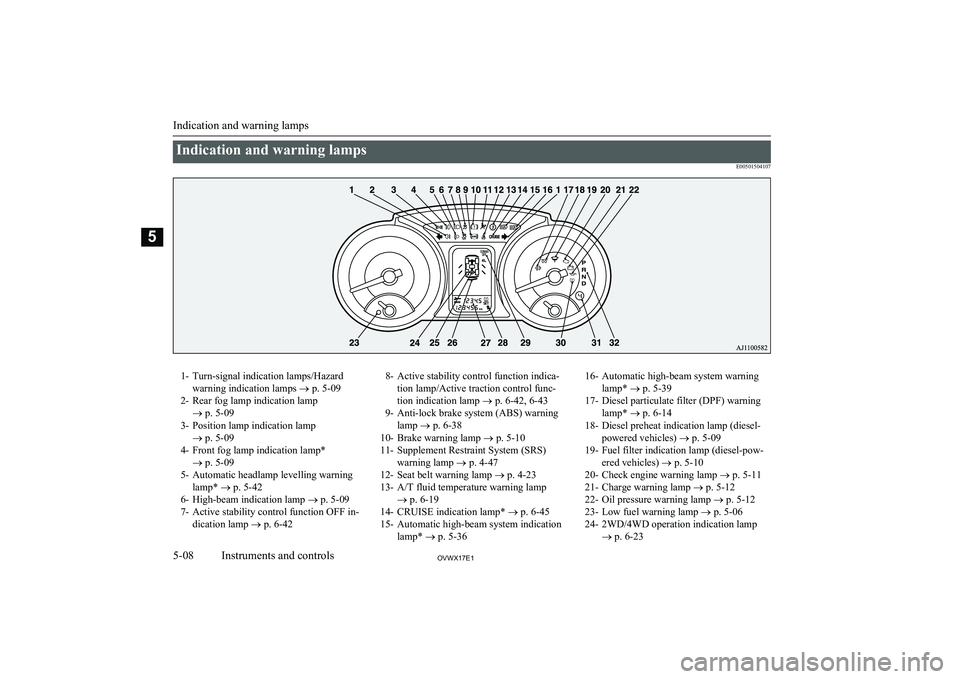
Indication and warning lampsE005015041071- Turn-signal indication lamps/Hazardwarning indication lamps ® p. 5-09
2- Rear fog lamp indication lamp ® p. 5-09
3- Position lamp indication lamp ® p. 5-09
4- Front fog lamp indication lamp* ® p. 5-09
5- Automatic headlamp levelling warning lamp* ® p. 5-42
6- High-beam indication lamp ® p. 5-09
7- Active stability control function OFF in- dication lamp ® p. 6-428- Active stability control function indica-
tion lamp/Active traction control func-
tion indication lamp ® p. 6-42, 6-43
9- Anti-lock brake system (ABS) warning lamp ® p. 6-38
10- Brake warning lamp ® p. 5-10
11- Supplement Restraint System (SRS) warning lamp ® p. 4-47
12- Seat belt warning lamp ® p. 4-23
13- A/T fluid temperature warning lamp ® p. 6-19
14- CRUISE indication lamp* ® p. 6-45
15- Automatic high-beam system indication lamp* ® p. 5-3616- Automatic high-beam system warning
lamp* ® p. 5-39
17- Diesel particulate filter (DPF) warning lamp* ® p. 6-14
18- Diesel preheat indication lamp (diesel- powered vehicles) ® p. 5-09
19- Fuel filter indication lamp (diesel-pow- ered vehicles) ® p. 5-10
20- Check engine warning lamp ® p. 5-11
21- Charge warning lamp ® p. 5-12
22- Oil pressure warning lamp ® p. 5-12
23- Low fuel warning lamp ® p. 5-06
24- 2WD/4WD operation indication lamp ® p. 6-23
Indication and warning lamps
5-08OVWX17E1Instruments and controls5
Page 117 of 394

Push the function button “SELECT”.
The setting display for your selected
item will appear.
Changing display units
It is possible to change the display units for the fuel consumption, driving range, average
speed, outside temperature, elevation, and at- mospheric pressure as shown below.
FUEL ECONO-
MYkm/L → L/100 km →
mpg (UK GALLON) → mpg (US GALLON)RANGEkm → milesSPEEDkm/h → mphOUTSIDE TEM-
PERATURE°C → °FELEVATIONm → ftBAROMETERhPa → mb → kPa → inHg
l Changing the display unit for fuel con-
sumption
1. Press the “←” or “→” function button to
select “FUEL ECONOMY”. Then press the “SELECT” function button.
2. Press the “←” or “→” function button to
select “km/L”. Then press the “SET” function button. The display will flash
twice, and the display unit will be upda- ted to the selected one.
NOTEl You can return to the previous display by
pressing the “BACK” function button.
3. After setting, press the “INFO” button to
return to the information display.
Changing the language
It is possible to set the display language of
the centre information display.
Centre information display
5-29OVWX17E1Instruments and controls5
Page 119 of 394

2.After setting the time notation, press the
“INFO” button to return to the informa- tion display.
Returning display items to their factorysettings
You can return the setting of each item to the
factory default settings.
NOTEl The factory settings are as follows:
• Fuel consumption: L/100 km
• Driving range: km
• Average speed: km/h
• Outside temperature: °C
• Elevation: m
• Atmospheric pressure: hPa
• Display language: English
• Time notation: 12-hour1. Push the “SELECT” function button.
2.
Press the “←” function button to select
“YES”.
3. Press the “SELECT” function button.
4. Once more press the “←” function but-
ton to select “YES”.
Centre information display
5-31OVWX17E1Instruments and controls5
Page 140 of 394
Economical drivingE00600100561
For economical driving, there are some tech- nical requirements that have to be met. Theprerequisite for low fuel consumption is a
properly adjusted engine. In order to achieve longer life of the vehicle and the most eco- nomical operation, we recommend you tohave the vehicle checked at regular intervals in accordance with the service standards.
Fuel economy and generation of exhaust gas
and noise are highly influenced by personal
driving habits as well as the particular operat- ing conditions. The following points shouldbe observed in order to minimize wear of
brakes, tyres and engine as well as to reduce
environmental pollution.
Starting
Avoid rapid acceleration and sudden starts;
such operation will result in higher fuel con-
sumption.
Shifting
Shift only at an appropriate speed and engine speed. Always use the highest gear possible.
The transfer shift lever should be set to “2H” when driving on normal roads and express
ways to obtain best possible fuel economy.
City traffic
Frequent starting and stopping increases the
average fuel consumption. Use roads with smooth traffic flow whenever possible. When driving on congested roads, avoid use of a
low gear at high engine speeds.
Idling
The vehicle consumes fuel even during
idling. Avoid extended idling whenever pos- sible.
Speed
At higher vehicle speed, more fuel is con-
sumed. Avoid driving at full speed. Even a
slight release of the accelerator pedal will save a significant amount of fuel.
Tyre inflation pressure
Check the tyre inflation pressures at regularintervals. Low tyre inflation pressure increa-ses road resistance and fuel consumption. In addition, low tyre pressures adversely affect
tyre wear and driving stability.
Load
Do not drive with unnecessary articles in the
luggage compartment. Especially during city
driving where frequent starting and stopping is necessary, the increased weight of the ve-
hicle will greatly affect fuel consumption. Al- so avoid driving with unnecessary luggage or carriers, etc., on the roof; the increased air re- sistance will increase fuel consumption.
Cold engine starting
Starting of a cold engine consumes more fuel.
Unnecessary fuel consumption is also caused by keeping a hot engine running. After the
engine is started, commence driving as soon
as possible.
Air conditioning
The use of the air conditioning will increase the fuel consumption.
Driving, alcohol and drugs
E00600200067
Driving after drinking alcohol is one of the
most frequent causes of accidents.
Economical driving
6-02OVWX17E1Starting and driving6
Page 188 of 394
Each tyre, including the spare, should be
checked monthly when cold and inflated to the inflation pressure recommended by thevehicle manufacturer on the tyre inflation
pressure label. (If your vehicle has tyres of a different size than the size indicated on the
tyre inflation pressure label, you should de-
termine the proper tyre inflation pressure for those tyres.)
As an added safety feature, your vehicle has been equipped with the tyre pressure moni-
toring system (TPMS) that illuminates a low
tyre pressure telltale when one or more of
your tyres is significantly under-inflated.
Accordingly, when the low tyre pressure tell-
tale illuminates, you should stop and check your tyres as soon as possible, and inflate
them to the proper pressure. Driving on a sig- nificantly under-inflated tyre causes the tyre to overheat and can lead to tyre failure.
Under-inflation also reduces fuel efficiency
and tyre tread life, and may affect the vehi- cle’s handling and stopping ability.
Please note that the tyre pressure monitoring
system (TPMS) is not a substitute for proper tyre maintenance, and it is the driver’s re-sponsibility to maintain correct tyre pressure,
even if under-inflation has not reached the level to trigger illumination of the tyre pres-
sure monitoring system (TPMS) low tyre pressure telltale.Your vehicle has also been equipped with a
warning lamp to indicate when the system is
not operating properly.
The warning lamp is combined with the low
tyre pressure telltale.
When the system detects a malfunction, the telltale will flash for approximately one mi-nute and then remain continuously illumina-
ted. This sequence will continue upon subse- quent vehicle start-ups as long as the mal-
function exists.
When the warning lamp is illuminated, the
system may not be able to detect or signal low tyre pressure as intended.
The tyre pressure monitoring system (TPMS)
malfunctions may occur for a variety of rea- sons, including the installation of replace- ment or alternate tyres or wheels on the vehi-
cle that prevent the tyre pressure monitoring system (TPMS) from functioning properly.
Always check the tyre pressure monitoring system (TPMS) malfunction telltale after re- placing one or more tyres or wheels on yourvehicle to ensure that the replacement or al-
ternate tyres and wheels allow the tyre pres- sure monitoring system (TPMS) to continueto function properly.If the warning lamp illuminates
while driving
E00637300082
1. If the warning lamp illuminates, avoid
hard braking, sharp steering manoeuvres
and high speeds. You should stop and
adjust the tyres to the proper inflationpressure as soon as possible. Refer to
“Tyres” on page 10-11.NOTEl When inspecting or adjusting the tyre pres-
sure, do not apply excessive force to the valve stem to avoid breakage.
l After inspecting or adjusting the tyre pres-
sure, always reinstall the valve cap on the valve stem.
Without the valve cap, dirt or moisture could
get into the valve, resulting in damage to the tyre inflation pressure sensor.
l Do not use metal valve caps, which may
cause a metal reaction, resulting in corrosion
and damage of the tyre inflation pressure sensors.
l Once adjustments have been made, the
warning lamp will go off after a few minutes of driving.
2. If the warning lamp remains illuminated
after you have been driving for about 10
minutes after you adjust the tyre infla- tion pressure, one or more of the tyresmay have a puncture. Inspect the tyreand if it has a puncture, have it repaired
by a MITSUBISHI MOTORS Author-
ized Service Point as soon as possible.
Tyre pressure monitoring system (TPMS)*
6-50OVWX17E1Starting and driving6
Page 198 of 394
Roof carrier precautionCAUTIONlMake sure that the weight of the luggage
does not exceed the allowable roof load.
If the allowable roof load is exceeded, this may cause damage to the vehicle.
The roof load is the total allowable load on
the roof (the weight of the roof carrier plus
the weight of luggage placed on the roof car- rier).
For specific figures, please refer to “Maxi-
mum roof load” on page 11-06 .
l When luggage is loaded onto the vehicle,
please make sure to drive slowly and avoid
excessive manoeuvres such as sudden brak- ing or quick turning.
In addition, place the luggage on the carrier
so that its weight is distributed evenly with the heaviest items on the bottom. Do not load items that are wider than the roof carri-
er.
The additional weight on the roof could raise
the vehicle’s centre of gravity and affect ve- hicle handling characteristics.
As a result, driving errors or emergency ma-
noeuvres could lead to a loss of control and
result in an accident.
l Before driving and after travelling a short
distance, always check the load to make sure it is securely fastened to the roof carrier.
Check periodically during your travel that
the load remains secure.NOTEl To prevent wind noise or reduction in fuel
economy, remove the roof carrier when not
in use.
l Before using an automatic car wash, remove
the roof carrier.
l Be sure that adequate clearance is main-
tained for raising the sunroof (if so equip-
ped) when installing a roof carrier.Trailer towing
E00610001850
In order to tow a trailer with your vehicle,
when having a trailer towing device mounted that meets all relevant regulations in your
area, consult a MITSUBISHI MOTORS Au-
thorized Service Point.
The regulations concerning the towing of a
trailer may differ from country to country. You are advised to obey the regulations in
each area.
CAUTIONl Danger of Accident!
A towing bar should be fitted according to MITSUBISHI MOTORS guidelines.
When you are going to tow a trailer, move
the transfer shift lever to “4H” position.
Selecting the “2H” drive may increase the differential oil temperature, resulting in pos-sible damage to the driving system.
Further, the drive train will be subjected to
excessive loading possibly leading to oil leakage, component seizure, or other serious faults.
Maximum towable weight with
brake and maximum trailer- nose weight
Never exceed the maximum towable weight
with brake and the maximum trailer-nose weight as listed in the specifications. (Referto “Vehicle weight” on page 11-06 .)
If you tow a trailer at an altitude of more than
1,000 m above sea-level, reduce your weight
by 10 % of the gross combination weight for
every increase of 1,000 m above sea-level, as the engine output is lowered owing to de-
crease in atmospheric pressure.
Trailer towing
6-60OVWX17E1Starting and driving6