wheel size MITSUBISHI SHOGUN 2017 Owner's Manual (in English)
[x] Cancel search | Manufacturer: MITSUBISHI, Model Year: 2017, Model line: SHOGUN, Model: MITSUBISHI SHOGUN 2017Pages: 394, PDF Size: 19 MB
Page 16 of 394
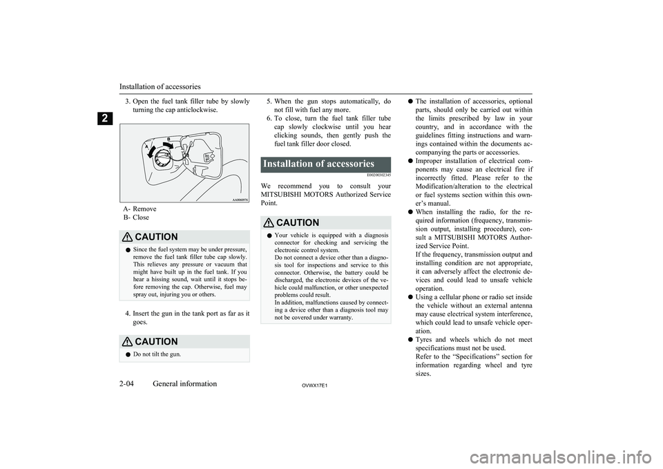
3.Open the fuel tank filler tube by slowly
turning the cap anticlockwise.
A- Remove B- Close
CAUTIONl Since the fuel system may be under pressure,
remove the fuel tank filler tube cap slowly. This relieves any pressure or vacuum that
might have built up in the fuel tank. If you
hear a hissing sound, wait until it stops be- fore removing the cap. Otherwise, fuel may
spray out, injuring you or others.
4. Insert the gun in the tank port as far as it
goes.
CAUTIONl Do not tilt the gun.5.
When the gun stops automatically, do
not fill with fuel any more.
6. To close, turn the fuel tank filler tube
cap slowly clockwise until you hear clicking sounds, then gently push the
fuel tank filler door closed.Installation of accessories
E00200302345
We recommend you to consult yourMITSUBISHI MOTORS Authorized Service
Point.
CAUTIONl Your vehicle is equipped with a diagnosis
connector for checking and servicing theelectronic control system.
Do not connect a device other than a diagno-
sis tool for inspections and service to this connector. Otherwise, the battery could be
discharged, the electronic devices of the ve- hicle could malfunction, or other unexpected
problems could result.
In addition, malfunctions caused by connect-
ing a device other than a diagnosis tool may not be covered under warranty.l The installation of accessories, optional
parts, should only be carried out within
the limits prescribed by law in your
country, and in accordance with the guidelines fitting instructions and warn-
ings contained within the documents ac-
companying the parts or accessories.
l Improper installation of electrical com-
ponents may cause an electrical fire if
incorrectly fitted. Please refer to the Modification/alteration to the electrical
or fuel systems section within this own-
er’s manual.
l When installing the radio, for the re-
quired information (frequency, transmis-
sion output, installing procedure), con- sult a MITSUBISHI MOTORS Author-
ized Service Point.
If the frequency, transmission output and installing condition are not appropriate,
it can adversely affect the electronic de- vices and could lead to unsafe vehicle operation.
l Using a cellular phone or radio set inside
the vehicle without an external antenna
may cause electrical system interference, which could lead to unsafe vehicle oper-ation.
l Tyres and wheels which do not meet
specifications must not be used.
Refer to the “Specifications” section for
information regarding wheel and tyre
sizes.
Installation of accessories
2-04OVWX17E1General information2
Page 171 of 394
NOTElFrequent crossing of streams can adversely
affect the life span of the vehicle; we recom-mend you to take the necessary measures toprepare, inspect, and repair the vehicle.Inspection and maintenance
following rough roadoperation E00606700048
After operating the vehicle in rough road
conditions, be sure to perform the following inspection and maintenance procedures:
l Check that the vehicle has not been dam-
aged by rocks, gravel, etc.
l Carefully wash the vehicle with water.
After washing, drive the vehicle slowly
while lightly depressing the brake pedal in order to dry out the brakes. If the brakes still do not function properly, we
recommend you to have the brakes
checked as soon as possible
l Remove the insects, dried grass, etc.
clogging the radiator core.
l After crossing a stream, be sure to have
the following items inspected at a
MITSUBISHI MOTORS Authorized
Service Point and take the necessary
measures.
• Check the brake system and, if neces-
sary, have it serviced.
• Check the engine, transmission, trans-
fer, and differential oil or grease level
and turbidity. If the oil or grease is
milky, it indicates water contamina-
tion. Replace it with new oil or grease.
• Grease the propeller shaft.
• Check the inside of the vehicle. If in-
gress of water is found, dry the carpetetc.
• Inspect the headlamps. If the head-
lamp bulb is flooded with water, we
recommend you to have it drained.Cautions on handling of 4-
wheel drive vehicles E00606802144
Tyres and wheels
Since the driving torque can be applied to the
4 wheels, the performance of the vehicle when operating in 4-wheel drive is greatly af- fected by the condition of the tyres.
Pay close attention to the tyres.
l Install specified tyres on all wheels. Re-
fer to “Tyres and wheels” on page
11-11.
l Be sure to fit all 4 tyres and wheels of
the same size and type.
When replacement of any of the tyres or
wheels is necessary, replace all of them.
l All tyres should be rotated whenever the
wear difference between the front and
rear tyres is recognizable.
Good vehicle performance cannot be expec- ted if there is a difference in wear between
tyres. Refer to “Tyre rotation” on page 10-13.
l Check the tyre inflation pressure regular-
ly.
l If the tyre inflation pressure is inappro-
priate, the transfer gear may make some
noise and shock while changing the drive mode.CAUTIONl Always use tyres of the same size, same
type, and same brand, and which have no wear differences. Using tyres which differ in
size, type, brand or the degree of wear will
cause excessive loading, resulting in possi- ble damage to the drive system.
Inspection and maintenance following rough road operation
6-33OVWX17E1Starting and driving6
Page 176 of 394
CAUTIONlEven the ABS cannot prevent the natural
laws of physics from acting on the vehicle. Itcannot for instance avoid accidents that may
result from excessive speed on bends or fol- lowing another vehicle too closely or aqua- planing. It should remain the driver’s task to
observe safety precautions to judge speeds and brake applications correctly in such con-
ditions.
l Be sure to use tyres of the same type and
size on 4 wheels.
If tyre types or sizes are mixed, ABS may not function normally.
l Never install a limited-slip differential,
which is not a MITSUBISHI MOTORS gen-
uine part, as the ABS may not function nor-
mally.
We recommend you to consult a MITSUBISHI MOTORS Authorized Serv-
ice Point.ABS warning lamp
E00607200532
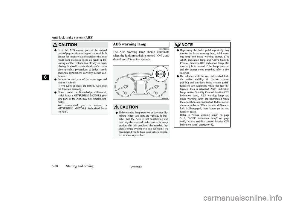
The ABS warning lamp should illuminate
when the ignition switch is turned “ON”, and
should go off in a few seconds.
CAUTIONl If the warning lamp stays on or does not illu-
minate when you start the vehicle, it indi-
cates that the ABS is not functioning and
that only the standard brake system is in op-
eration. (In this condition the standard hy- draulic brake system will still function.) We
recommend you to have your vehicle inspec- ted as soon as possible.NOTEl Depressing the brake pedal repeatedly may
turn on the brake warning lamp, ABS warn-ing lamp and brake warning buzzer. (The
ASTC indication lamp and Active Stability
Control function OFF indication lamp also
turn on.) It is normal if the lamp goes out and the buzzer stops sounding after a few
seconds.
l On vehicles with the rear differential lock,
the active stability & traction control
(ASTC) and anti-lock brake system (ABS)
functions are suspended while the rear dif- ferential lock is activated. ASTC indication
lamp, Active Stability Control function OFF indication lamp, ABS warning lamp and
brake warning lamp are illuminated while these functions are suspended. It does not in-
dicate a problem. When the rear differential lock is disengaged, these lamps go out and
function again.
Refer to “Brake warning lamp” on page
5-10 , “ASTC indication lamp” on page
6-40 , “Active stability control function OFF
indication lamp” on page 6-42.
Anti-lock brake system (ABS)
6-38OVWX17E1Starting and driving6
Page 178 of 394
CAUTIONlDo not leave the steering wheel turned all
the way in one direction. This can causedamage to the power steering system.Active stability & traction
control (ASTC) E00613800230
The active stability & traction control(ASTC) takes overall control of the anti-lockbrake system, Active Stability Control func-
tion and active traction control function to
maintain the vehicle’s stability and traction. Please read this section in conjunction withthe pages on the anti-lock brake system, Ac-
tive Stability Control function and active
traction control function.
Anti-lock brake system (ABS) ® p. 6-37
Active stability control function ® p. 6-42
Active traction control function ® p. 6-43
CAUTIONl Do not over-rely on the ASTC. Even when
the ASTC is operating, there are limits to how far it can ensure vehicle stability; reck-
less driving may lead to accidents. Always
drive carefully, taking account of the road conditions.CAUTIONl Be sure to use the same specified type and
size of tyre on all 4 wheels. Otherwise, there
is a possibility that the ASTC will not work properly.NOTEl An operation noise may be emitted from the
engine compartment in the following situa-
tions. The sound is associated with checking the operations of the ASTC. At this time,
you may feel a shock from the brake pedal if
you depress it. These do not indicate a mal- function.
• When the ignition switch is set to the
“ON” position.
• When the vehicle is driven for a while af-
ter the engine is turned on.
l When the ASTC is activated, you may feel a
vibration in the vehicle body or hear a whin-ing sound from the engine compartment.
This indicates that the system is operating
normally. It does not indicate a malfunction.
l When the anti-lock brake system warning
lamp is illuminated, the ASTC is not active.NOTEl On vehicles with the rear differential lock,
the ASTC and ABS functions are suspended
while the rear differential lock is activated. ASTC indication lamp, Active Stability
Control function OFF indication lamp, ABS warning lamp and brake warning lamp are
illuminated while these functions are sus- pended. It does not indicate a problem.
When the rear differential lock is disengag- ed, these lamps go out and function again.
Refer to “Brake warning lamp” on page
5-10 , “ABS warning lamp” on page 6-38,
“Active stability control function OFF indi- cation lamp” on page 6-42.ASTC indication lamp
E00618000035
The ASTC indication lamp shows the operat-
ing status of the Active Stability Controlfunction and active traction control function.
For details, see these sections of this owner’s
manual:
Active stability control function indication
lamp ® p. 6-42
Active stability & traction control (ASTC)
6-40OVWX17E1Starting and driving6
Page 188 of 394
Each tyre, including the spare, should be
checked monthly when cold and inflated to the inflation pressure recommended by thevehicle manufacturer on the tyre inflation
pressure label. (If your vehicle has tyres of a different size than the size indicated on the
tyre inflation pressure label, you should de-
termine the proper tyre inflation pressure for those tyres.)
As an added safety feature, your vehicle has been equipped with the tyre pressure moni-
toring system (TPMS) that illuminates a low
tyre pressure telltale when one or more of
your tyres is significantly under-inflated.
Accordingly, when the low tyre pressure tell-
tale illuminates, you should stop and check your tyres as soon as possible, and inflate
them to the proper pressure. Driving on a sig- nificantly under-inflated tyre causes the tyre to overheat and can lead to tyre failure.
Under-inflation also reduces fuel efficiency
and tyre tread life, and may affect the vehi- cle’s handling and stopping ability.
Please note that the tyre pressure monitoring
system (TPMS) is not a substitute for proper tyre maintenance, and it is the driver’s re-sponsibility to maintain correct tyre pressure,
even if under-inflation has not reached the level to trigger illumination of the tyre pres-
sure monitoring system (TPMS) low tyre pressure telltale.Your vehicle has also been equipped with a
warning lamp to indicate when the system is
not operating properly.
The warning lamp is combined with the low
tyre pressure telltale.
When the system detects a malfunction, the telltale will flash for approximately one mi-nute and then remain continuously illumina-
ted. This sequence will continue upon subse- quent vehicle start-ups as long as the mal-
function exists.
When the warning lamp is illuminated, the
system may not be able to detect or signal low tyre pressure as intended.
The tyre pressure monitoring system (TPMS)
malfunctions may occur for a variety of rea- sons, including the installation of replace- ment or alternate tyres or wheels on the vehi-
cle that prevent the tyre pressure monitoring system (TPMS) from functioning properly.
Always check the tyre pressure monitoring system (TPMS) malfunction telltale after re- placing one or more tyres or wheels on yourvehicle to ensure that the replacement or al-
ternate tyres and wheels allow the tyre pres- sure monitoring system (TPMS) to continueto function properly.If the warning lamp illuminates
while driving
E00637300082
1. If the warning lamp illuminates, avoid
hard braking, sharp steering manoeuvres
and high speeds. You should stop and
adjust the tyres to the proper inflationpressure as soon as possible. Refer to
“Tyres” on page 10-11.NOTEl When inspecting or adjusting the tyre pres-
sure, do not apply excessive force to the valve stem to avoid breakage.
l After inspecting or adjusting the tyre pres-
sure, always reinstall the valve cap on the valve stem.
Without the valve cap, dirt or moisture could
get into the valve, resulting in damage to the tyre inflation pressure sensor.
l Do not use metal valve caps, which may
cause a metal reaction, resulting in corrosion
and damage of the tyre inflation pressure sensors.
l Once adjustments have been made, the
warning lamp will go off after a few minutes of driving.
2. If the warning lamp remains illuminated
after you have been driving for about 10
minutes after you adjust the tyre infla- tion pressure, one or more of the tyresmay have a puncture. Inspect the tyreand if it has a puncture, have it repaired
by a MITSUBISHI MOTORS Author-
ized Service Point as soon as possible.
Tyre pressure monitoring system (TPMS)*
6-50OVWX17E1Starting and driving6
Page 307 of 394
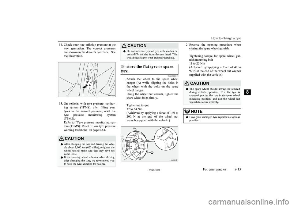
14.Check your tyre inflation pressure at the
next gasstation. The correct pressures
are shown on the driver’s door label. See the illustration.
15. On vehicles with tyre pressure monitor-
ing system (TPMS), after filling your tyres to the correct pressure, reset the tyre pressure monitoring system(TPMS).
Refer to “Tyre pressure monitoring sys-
tem (TPMS): Reset of low tyre pressure
warning threshold” on page 6-51.
CAUTIONl After changing the tyre and driving the vehi-
cle about 1,000 km (620 miles), retighten the
wheel nuts to make sure that they have not come loose.
l If the steering wheel vibrates when driving
after changing the tyre, we recommend you to have the tyres checked for balance.CAUTIONl Do not mix one type of tyre with another or
use a different size from the one listed. This
would cause early wear and poor handling.To store the flat tyre or spare
tyre
E00803400192
1. Attach the wheel to the spare wheel
hanger (A) while aligning the holes in
the wheel with the bolts on the spare
wheel hanger.
Using the wheel nut wrench, tighten the spare wheel bolts firmly.
Tightening torque
37 to 54 Nm
(Achieved by applying a force of 140 to
200 N at the end of the wheel nut wrench supplied with the vehicle.)
2. Reverse the opening procedure when
closing the spare wheel garnish.
Tightening torque for spare wheel gar- nish mounting bolt
11 to 25 Nm
(Achieved by applying a force of 40 to
92 N at the end of the wheel nut wrench supplied with the vehicle.)CAUTIONl The spare wheel should always be secured
during vehicle operation. If a flat tyre is changed, put the flat tyre in the spare wheel
mounting position, and use the wheel nut
wrench to secure it firmly.NOTEl Have your damaged tyre repaired as soon as
possible.
How to change a tyre
8-15OVWX17E1For emergencies8
Page 330 of 394
Vehicles for Russia, Kazakhstan, Belarus and UkraineTyre sizeUp to 5 passengersUp to max. loadAt trailer towingFrontRearFrontRearFrontRear265/65R17 112H2.0 bar (200 kPa) *
2.2 bar (220 kPa)2.2 bar (220 kPa) *
2.4 bar (240 kPa)2.4 bar (240 kPa)2.8 bar (280 kPa)2.6 bar (260 kPa)3.0 bar (300 kPa)265/60R18 110H2.0 bar (200 kPa) *
2.2 bar (220 kPa)2.2 bar (220 kPa) *
2.4 bar (240 kPa)2.4 bar (240 kPa)2.8 bar (280 kPa)2.6 bar (260 kPa)3.0 bar (300 kPa)* : Vehicles for 3000 models
Check the tyre inflation pressure of all the tyres while they are cold; if insufficient or excessive, adjust to the specified value.
After the tyre inflation pressure has been adjusted, check the tyres for damage and air leaks. Be sure to put caps on the valves.
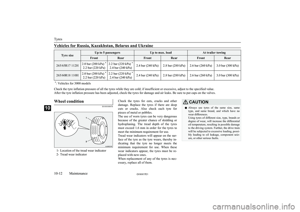
Wheel condition
E01001800478
1- Location of the tread wear indicator
2- Tread wear indicator
Check the tyres for cuts, cracks and other
damage. Replace the tyres if there are deep
cuts or cracks. Also check each tyre for pieces of metal or pebbles.
The use of worn tyres can be very dangerous
because of the greater chance of skidding or
hydroplaning. The tread depth of the tyres
must exceed 1.6 mm in order for the tyres to meet the minimum requirement for use.
Tread wear indicators will appear on the sur-
face of the tyre as the tyre wears, thereby in-
dicating that the tyre no longer meets the
minimum requirement for use. When these
wear indicators appear, the tyres must be re-
placed with new ones.
When replacement of any of the tyres is nec- essary, replace all of them.CAUTIONl Always use tyres of the same size, same
type, and same brand, and which have no wear differences.
Using tyres of different size, type, brands or
degree of wear, will increase the differential
oil temperature, resulting in possible damage to the driving system. Further, the drive train
will be subjected to excessive loading, possi- bly leading to oil leakage, component seiz-ure, or other serious faults.
Tyres
10-12OVWX17E1Maintenance10
Page 331 of 394
Replacing tyres and wheels
E01007201530
CAUTIONlAvoid using different size tyres from the one
listed and the combined use of different
types of tyres, as this can affect driving safe- ty.
Refer to “Tyres and wheels” on page
11-11.
l Even if a wheel has the same rim size and
offset as the specified type of wheel, its
shape may prevent it from being fitted cor- rectly. We recommend you to consult a spe-
cialist before using wheels that you have.
l If your vehicle is equipped with a tyre pres-
sure monitoring system, only MITSUBISHI
MOTORS genuine wheels should be used.
Use of another type of wheel risks air leaks and sensor damage, as it will not be possible
to install the tyre pressure sensor properly.
Refer to “Tyre pressure monitoring system
(TPMS)” on page 6-48.
Wheel balance
On vehicles equipped with 17x7 1/2J size
aluminium wheels (round rim type), if you
need to balance a wheel, put the balance weight (A) on the specified position which is
spoke side from the notch (B) on the inner surface of the wheel.
There is a possibility that the balance weight
is interfered the related brake part if it is put
any place other than the specified position.
For details, we recommend you to consult a MITSUBISHI MOTORS Authorized Service
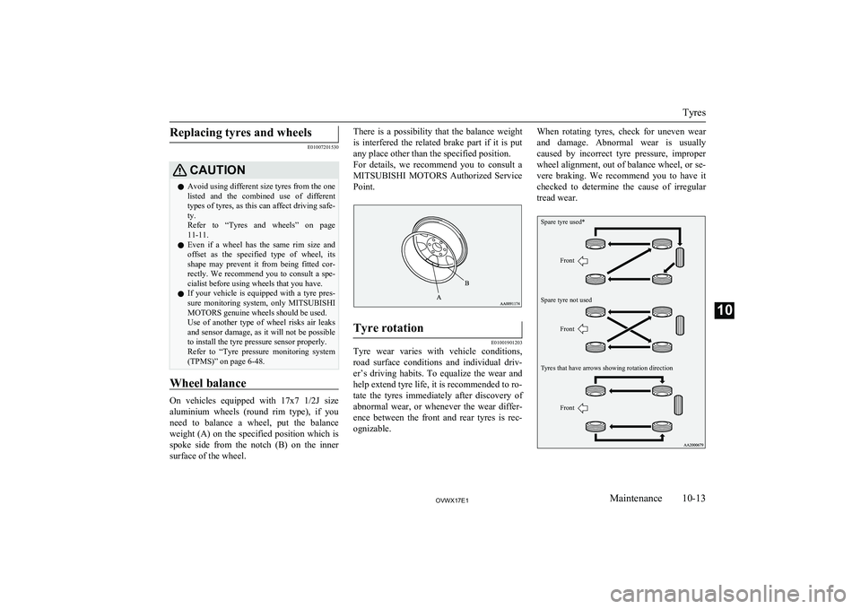
Point.Tyre rotation
E01001901203
Tyre wear varies with vehicle conditions,
road surface conditions and individual driv- er’s driving habits. To equalize the wear andhelp extend tyre life, it is recommended to ro-
tate the tyres immediately after discovery of
abnormal wear, or whenever the wear differ- ence between the front and rear tyres is rec-
ognizable.
When rotating tyres, check for uneven wear
and damage. Abnormal wear is usually caused by incorrect tyre pressure, improper wheel alignment, out of balance wheel, or se-
vere braking. We recommend you to have it checked to determine the cause of irregular
tread wear.Spare tyre used*Spare tyre not usedTyres that have arrows showing rotation directionFrontFrontFront
Tyres
10-13OVWX17E1Maintenance10
Page 332 of 394
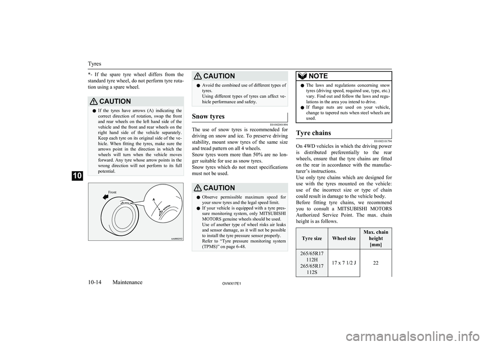
*- If the spare tyre wheel differs from thestandard tyre wheel, do not perform tyre rota-
tion using a spare wheel.CAUTIONl If the tyres have arrows (A) indicating the
correct direction of rotation, swap the front and rear wheels on the left hand side of the
vehicle and the front and rear wheels on the
right hand side of the vehicle separately. Keep each tyre on its original side of the ve-hicle. When fitting the tyres, make sure the
arrows point in the direction in which the wheels will turn when the vehicle moves
forward. Any tyre whose arrow points in the
wrong direction will not perform to its full potential.Front
CAUTIONl Avoid the combined use of different types of
tyres.
Using different types of tyres can affect ve-
hicle performance and safety.Snow tyres
E01002001894
The use of snow tyres is recommended for
driving on snow and ice. To preserve driving stability, mount snow tyres of the same size and tread pattern on all 4 wheels.
Snow tyres worn more than 50% are no lon-
ger suitable for use as snow tyres.
Snow tyres which do not meet specifications must not be used.
CAUTIONl Observe permissible maximum speed for
your snow tyres and the legal speed limit.
l If your vehicle is equipped with a tyre pres-
sure monitoring system, only MITSUBISHI
MOTORS genuine wheels should be used.
Use of another type of wheel risks air leaks and sensor damage, as it will not be possible
to install the tyre pressure sensor properly.
Refer to “Tyre pressure monitoring system
(TPMS)” on page 6-48.NOTEl The laws and regulations concerning snow
tyres (driving speed, required use, type, etc.)
vary. Find out and follow the laws and regu- lations in the area you intend to drive.
l If flange nuts are used on your vehicle,
change to tapered nuts when steel wheels are used.Tyre chains
E01002101794
On 4WD vehicles in which the driving power
is distributed preferentially to the rear wheels, ensure that the tyre chains are fitted
on the rear in accordance with the manufac- turer’s instructions.
Use only tyre chains which are designed for use with the tyres mounted on the vehicle: use of the incorrect size or type of chain
could result in damage to the vehicle body.
Before fitting tyre chains, we recommend you to consult a MITSUBISHI MOTORS
Authorized Service Point. The max. chain
height is as follows.
Tyre sizeWheel size
Max. chain
height[mm]265/65R17 112H
265/65R17 112S
17 x 7 1/2 J22Tyres
10-14OVWX17E1Maintenance10
Page 333 of 394
![MITSUBISHI SHOGUN 2017 Owners Manual (in English) Tyre sizeWheel size
Max. chainheight[mm]265/60R18 110H18 x 7 1/2 J
The speed limit for tyre chain is 50 km/h(30 mph) and remove the tyre chains as soon as possible on snow free roads.
MITSUBISHI SHOGUN 2017 Owners Manual (in English) Tyre sizeWheel size
Max. chainheight[mm]265/60R18 110H18 x 7 1/2 J
The speed limit for tyre chain is 50 km/h(30 mph) and remove the tyre chains as soon as possible on snow free roads.](/img/19/34886/w960_34886-332.png)
Tyre sizeWheel size
Max. chainheight[mm]265/60R18 110H18 x 7 1/2 J
The speed limit for tyre chain is 50 km/h(30 mph) and remove the tyre chains as soon as possible on snow free roads.
CAUTIONl As your vehicle is equipped with anti-lock
brake system (ABS), in order to ensure that the anti-lock brake system (ABS) will oper- ate correctly in situations where tyre chains
have been fitted, drive in “4H”, “4HLc” or “4LLc”.
l Practice fitting the chains before you need
them.
Don’t expect help from other people in the
cold.
l Choose a clear straight stretch of road where
you can pull over and still be seen while you are fitting the chains.
l Do not fit chains before you need them. This
will wear out your tyres and the road sur-
face.
l After driving around 100-300 metres, stop
and retighten the chains.
l Drive carefully and do not exceed 50 km/h
(30 mph). Remember, fitting chains is notgoing to stop accidents from happening.
l When tyre chains are installed, take care that
they do not damage the disc wheel or body.CAUTIONl An aluminium wheel can be damaged by a
tyre chain while driving. When fitting a tyre
chain on an aluminium wheel, take care that any part of the chain and fitting cannot be
brought into contact with the wheel.
l When installing or removing the tyre chains,
take care that hands and other parts of your
body are not injured by the sharp edges of
the vehicle body.NOTEl The laws and regulations concerning the use
of tyre chains vary. Always follow local laws and regulations.
In most countries, it is prohibited by law to
use tyre chains on roads without snow.Parking brake break-in
E01008300010
Break-in the parking brake linings whenever
the brake performance of the parking brake is insufficient or whenever the parking brake
linings and/or discs are replaced, in order to
assure the best brake performance.
This procedure is described in the vehicle service manual and can be carried out by a
MITSUBISHI MOTORS Authorized Service
Point.
Wiper blade rubber
replacement E01008200208
1. Lift the wiper arm off the windscreen. 2. Pull the wiper blade until its stopper (A)
disengages from the hook (B). Then, pull the wiper blade further to remove it.NOTEl Do not allow the wiper arm to fall onto the
windscreen; it could damage the glass.
3. Attach the retainers (C) to a new wiper
blade.
Parking brake break-in
10-15OVWX17E1Maintenance10