jump start MITSUBISHI SPYDER 1990 Service Repair Manual
[x] Cancel search | Manufacturer: MITSUBISHI, Model Year: 1990, Model line: SPYDER, Model: MITSUBISHI SPYDER 1990Pages: 2103, PDF Size: 68.98 MB
Page 409 of 2103
![MITSUBISHI SPYDER 1990 Service Repair Manual Scan tool 16
General scan tool A/C Clutch Relay Circuit ,.
33
[Comment]Coinpressor clutch relay shortedBackgroundl control circuit defectivel The PCM provides a switched groun MITSUBISHI SPYDER 1990 Service Repair Manual Scan tool 16
General scan tool A/C Clutch Relay Circuit ,.
33
[Comment]Coinpressor clutch relay shortedBackgroundl control circuit defectivel The PCM provides a switched groun](/img/19/57345/w960_57345-408.png)
Scan tool 16
General scan tool A/C Clutch Relay Circuit ,.
33
[Comment]Coinpressor clutch relay shortedBackgroundl control circuit defectivel The PCM provides a switched ground to the clutch relay.
l circuit driver in PCMlThe PCM can prevent operation of the clutch in selected situations such as duringwide-open or for a period at start-up.l This DTC indicates an open or short-circuit conditi on in the circuit.Range of Checkl Ignition ONl Battery voltage: or morel 30 seconds or more after starting engineSet ConditionlOpen or short circuit is detected in the A/C clutch relay control circuit for 3 seconds.
N G relay. Replace
. .
. 55 On-vehicle Service) me (Refer to GROUF
OK
Measure at the PCM connectors and lDisconnect the connector, and measure at the harnes s side.
l Voltage between 36 and ground, and 64 and ground
(Ignition switch: ON)
switch: ON)
OK: Battery positive
l Connect a jumper wire between and the ground.
(Ignition switch: ON)
(A/C switch: ON)
OK:
compressor clutch is turned on
N G
Check the system (Refer to GROUP 55 Troubleshooting) Check trouble symptom.
NG
Replace the . ,
I ,
TSB Revision
Page 636 of 2103

ENGINE (TURBO)
AND
ENGINE> Troubleshooting
Analyzer
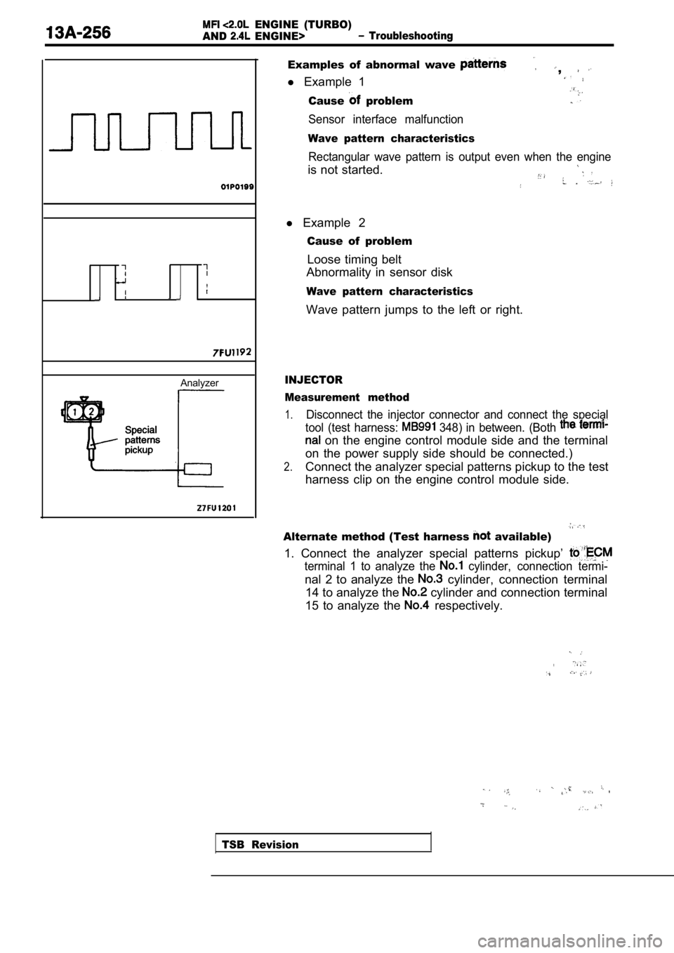
Examples of abnormal wave ,
l Example 1
Cause problem
Sensor interface malfunction
Wave pattern characteristics
Rectangular wave pattern is output even when the en gine
is not started.
l Example 2
Cause of problem
Loose timing belt
Abnormality in sensor disk
Wave pattern characteristics
Wave pattern jumps to the left or right.
INJECTOR
Measurement method
1.Disconnect the injector connector and connect the s pecial
tool (test harness:
348) in between. (Both
on the engine control module side and the terminal
on the power supply side should be connected.)
2.Connect the analyzer special patterns pickup to the test
harness clip on the engine control module side.
Alternate method (Test harness available)
1. Connect the analyzer special patterns pickup’
terminal 1 to analyze the cylinder, connection termi-
nal 2 to analyze the cylinder, connection terminal
14 to analyze the
cylinder and connection terminal
15 to analyze the
respectively.
TSB Revision
Page 770 of 2103

ENGINE AND EMISSION CONTROL Auto-cruise Control
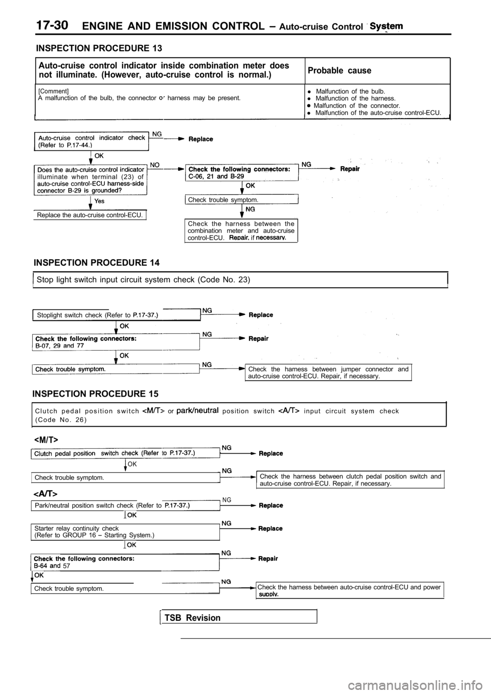
INSPECTION PROCEDURE 13
Auto-cruise control indicator inside combination meter does
not illuminate. (However, auto-cruise control is no rmal.)Probable cause
[Comment]A malfunction of the bulb, the connector harness may be present. l
Malfunction of the bulb.
l Malfunction of the harness. Malfunction of the connector.
l Malfunction of the auto-cruise control-ECU.
to
illuminate when terminal (23) of
Check trouble symptom.
Replace the auto-cruise control-ECU. Check the harness between the
combination meter and auto-cruise
control-ECU.
if
INSPECTION PROCEDURE 14
Stop light switch input circuit system check (Code No. 23)II
Stoplight switch check (Refer to
Check the harness between jumper connector and
auto-cruise control-ECU. Repair, if necessary.
INSPECTION PROCEDURE 15 C l u t c h p e d a l p o s i t i o n s w i t c h
or p o s i t i o n s w i t c h i n p u t c i r c u i t s y s t e m c h e c k
( C o d e N o . 2 6 )
Check trouble symptom.
OK
NG
Check the harness between clutch pedal position swi tch and
auto-cruise control-ECU. Repair, if necessary.
Park/neutral position switch check (Refer to
Starter relay continuity check
(Refer to GROUP 16 Starting System.)
57
Check trouble symptom. Check the harness between auto-cruise control-ECU and power
TSB Revision
Page 779 of 2103

C o n t r o l
(3) Connect a jumper wire
servo connector of the main harness and pin 3 of the
speed control servo.The other three pins
should show battery voltage. If not, replace the se
rvo.
(4) Using an ohmmeter, connect one lead to
ground. With the
servo connector of the main harness, the meter shou ld
show continuity. If not, repair the ground
as
necessary. .
Vacuum Test
(1) Remove the speed control cable at the throttle
body end.
(2)Disconnect the electrical connector and
lines at the servo.
(3) Connect battery voltage to pin No. 3 of the
(4) Ground the remaining three servo pins 1, 2
(5) Connect a hand held vacuum pump to the servo va cuum
nipple and apply 10 to 15 inches of vacuum.
(6) The cable should pull in and hold for as long a s vacuum
is applied.
VACUUM SUPPLY Engine (Non-turbo)>
(1) Disconnect the vacuum hose at the servo and ins tall
a vacuum gauge in the hose.
(2) Start engine and observe the gauge at idle. The vacuum
gauge should read at least ten inches of mercury. Shut
off engine, the vacuum should continue to hold inches
of mercury.
(3) If vacuum does not meet this requirement, check and
correct the following vacuum leaks:
Vacuum lines
Vacuum reservoir
Servo vacuum
Poor engine performance
I-cruise control
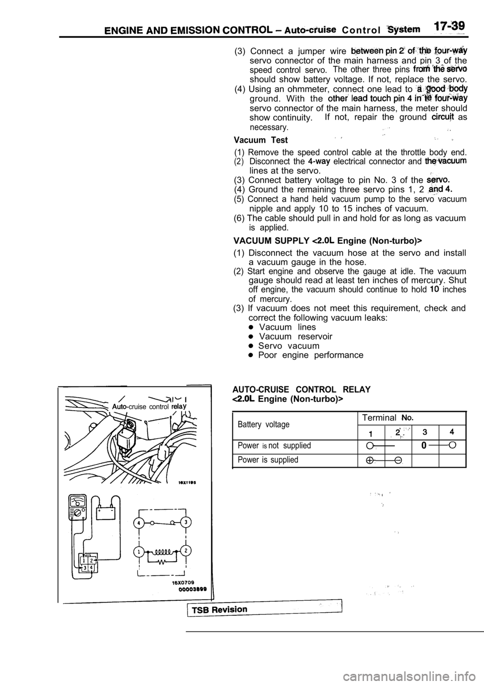
AUTO-CRUISE CONTROL RELAY
Engine (Non-turbo)>
Battery voltage
Power
isnot supplied
Power is supplied
Terminal
,
,
,0
Page 796 of 2103

ENGINE AND
Emission Control System
Vacuum
Engine speed
TSB Revision
4I
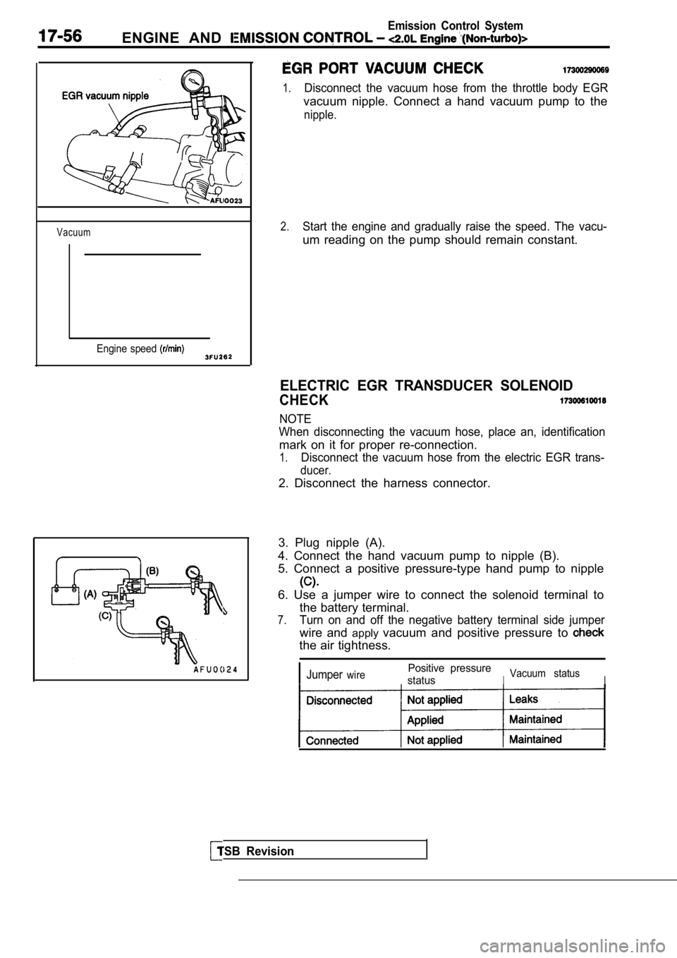
1.Disconnect the vacuum hose from the throttle body EGR
vacuum nipple. Connect a hand vacuum pump to the
nipple.
2.Start the engine and gradually raise the speed. The vacu-
um reading on the pump should remain constant.
ELECTRIC EGR TRANSDUCER SOLENOID
CHECK
NOTE
When disconnecting the vacuum hose, place an, ident ification
mark on it for proper re-connection.
1.Disconnect the vacuum hose from the electric EGR trans-
ducer.
2. Disconnect the harness connector.
3. Plug nipple (A).
4. Connect the hand vacuum pump to nipple (B).
5. Connect a positive pressure-type hand pump to ni pple
6. Use a jumper wire to connect the solenoid terminal to
the battery terminal.
7.Turn on and off the negative battery terminal side jumper
wire and applyvacuum and positive pressure to
the air tightness.
JumperwirePositive pressure
status
IVacuum statusI